
EFFICIENT IMAGE COMPRESSION ALGORITHMS USING EVOLVED WAVELETS · EFFICIENT IMAGE COMPRESSION...
21
International Journal of ISSN 0974-2107 Systems and Technologies Vol.4, No.2, pp 127-146 127 IJST KLEF 2011 EFFICIENT IMAGE COMPRESSION ALGORITHMS USING EVOLVED WAVELETS 1 .G.CHENCHU KRISHNAIAH* 2 .T.JAYACHANDRAPRASAD 3 .M.N.GIRI PRASAD 1 .ECE DEPT.,GKCE,Sullurpet-524121,A.P,India. Email:[email protected] 2 .ECEDEPT.,RGMCET,Nandyal-528502,A.P,India 3 .ECEDEPT.,JNTUCE,Pulivendula-515002,A.P,India Abstract: The 9/7 and 5/3 lifting based wavelet filters are widely used in different image compression schemes, such as JPEG 2000 image compression standard. The performance of a hardware implementation of the 9/7 and 5/3 filter banks depends on the accuracy with which filter coefficients are represented. In this paper an attempt has been made to study the performance of 9/7 and 5/3 wavelets on photographic images (monochrome and color) and estimated Peak Signal to Noise Ratio (PSNR), Compression Ratio (CR), Mean Square Error (MSE), Encoding Time, Decoding Time, Transforming Time or Decomposition Time…etc. This study shows that the 5/3 wavelet transform out perform the 9/7 wavelet transform. Key words: Low complexity, efficient, 5/3 wavelet filter, 9/7 wavelet filter, implementation, image compression, Algorithms, Evolved Wavelets. Introduction The Discrete Wavelet Transform (DWT) has gained wide popularity due to its excellent decorrelation property[1], as a consequence many modern image and video compression systems embody the DWT as the transform stage [2], [3]. It is widely recognized that the 9/7 filters [4] are among the best filters for wavelet based image compression [5]. In fact the JPEG2000 image coding standard [6] employs the 9/7 filters as the default wavelet filters for lossy compression, fostering many research efforts in the development of fast and efficient hardware codecs.
Transcript of EFFICIENT IMAGE COMPRESSION ALGORITHMS USING EVOLVED WAVELETS · EFFICIENT IMAGE COMPRESSION...
International Journal of ISSN 0974-2107
Systems and Technologies
Vol.4, No.2, pp 127-146
127
IJST
KLEF 2011
EFFICIENT IMAGE COMPRESSION
ALGORITHMS USING EVOLVED WAVELETS
1.G.CHENCHU KRISHNAIAH*
2.T.JAYACHANDRAPRASAD
3.M.N.GIRI PRASAD
1.ECE DEPT.,GKCE,Sullurpet-524121,A.P,India.
Email:[email protected] 2.ECEDEPT.,RGMCET,Nandyal-528502,A.P,India
3.ECEDEPT.,JNTUCE,Pulivendula-515002,A.P,India
Abstract: The 9/7 and 5/3 lifting based wavelet filters are widely used in different
image compression schemes, such as JPEG 2000 image compression standard. The
performance of a hardware implementation of the 9/7 and 5/3 filter banks depends on
the accuracy with which filter coefficients are represented. In this paper an attempt
has been made to study the performance of 9/7 and 5/3 wavelets on photographic
images (monochrome and color) and estimated Peak Signal to Noise Ratio (PSNR),
Compression Ratio (CR), Mean Square Error (MSE), Encoding Time, Decoding
Time, Transforming Time or Decomposition Time…etc. This study shows that the
5/3 wavelet transform out perform the 9/7 wavelet transform.
Key words: Low complexity, efficient, 5/3 wavelet filter, 9/7 wavelet filter,
implementation, image compression, Algorithms, Evolved Wavelets.
Introduction
The Discrete Wavelet Transform (DWT) has gained wide popularity due to its
excellent decorrelation property[1], as a consequence many modern image and video
compression systems embody the DWT as the transform stage [2], [3]. It is widely
recognized that the 9/7 filters [4] are among the best filters for wavelet based image
compression [5]. In fact the JPEG2000 image coding standard [6] employs the 9/7
filters as the default wavelet filters for lossy compression, fostering many research
efforts in the development of fast and efficient hardware codecs.
G.Chenchu Krishnaiah
128
The performance of a hardware implementation of the 9/7 filter bank depends
on the accuracy with which filter co-efficient are represented. However high
precision representation increases hardware resources and processing time. To reduce
the complexity of the 9/7 filters the lifting scheme [7] can be adopted. Unfortunately
the lifting scheme increases hardware timing accumulation due to its serial nature [8],
so that for certain applications it cannot be employed. The flipping structure [8] is an
attractive alternative to the standard lifting scheme DWT, since it reduces timing
accumulation, however it still requires multiplications.
Complexity reduction can be achieved resorting to a filter bank
implementation; in particular very good results can be obtained with the cascaded
method proposed in [9]. The basic idea described in [9] is to minimize the number of
bit required to represent the 9/7 coefficients. Since this operation would move filters
zeros from their original position, the authors modify some terms to account for zeros
compensation. Currently the compatibility of low complexity 9/7 filters
implementation with floating point ones has not been stressed yet. The aim of this
paper is to show that great complexity reduction can be achieved analyzing the 9/7
filters directly from their analytical derivation [4]. In particular the proposed solution
shows negligible quality loss if employed in the direct DWT, with the floating point
9/7 filter bank in the inverse DWT.
1. THEORETICAL DERIVATION
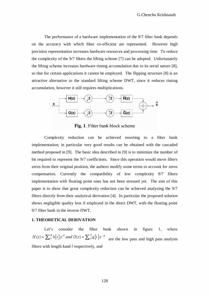
Let’s consider the filter bank shown in figure 1, where
are the low pass and high pass analysis
filters with length kand l respectively, and

Efficient Image….
129
the low pass and high pass synthesis
ones with length and . It is well known that wavelet filter banks ought to satisfy
the perfect reconstruction conditions [10]:
Imposing the biorthogonality condition together with filters symmetry ( (z) = H(-z)
and G(z) = (-z)) we can rewrite the perfect reconstruction conditions as:
As shown in [4], writing the non distortion condition 3 on h and in terms of
trigonometric polynomials, it becomes:
Moreover, together with divisibility of H and respectively by and
[4] it leads to:
Where ( )R is an odd polynomial in ( )Cos and 2l=k+ .
The 9/7 filters have been proposed in [4] as a particular case of trigonometric
polynomial that satisfy equation 6 with R 0, k=4 and =4. When R 0, k=4 and
=4 equation 6 becomes
The term cos8( / 2) can be split into two equal parts with degree 4. The polynomial in
sin ( / 2) can be considered as a third order equation and factorized into two
polynomials with degree 2 and 4 respectively in order to obtain:
Where r is the real solution of the third order equation
2 31 20 4 20 10 / 20 0 (9)x x x

G.Chenchu Krishnaiah
130
and b. Equation 8 leads to:
42 4cos( / 2)
( ) [ sin( / 2) sin( / 2) ] (10)H a ba
Developing equations 10 and 11 we can build filters coefficients as shown in table 1
where K1 = 2 3 1 2
3 11 1 12 8 2, , , .
2 8 32 2 8
ba r
bK k J and J
a a a r r
2. THE LIFTING SCHEME
The conventional structure of two-channel filter banks based on lifting steps is shown
in Figure 2. The incoming signal (z-domain) is split into two paths (polyphase
transform) containing the values at even or odd sample positions. In order to devise
the filter
Efficient Image….
131
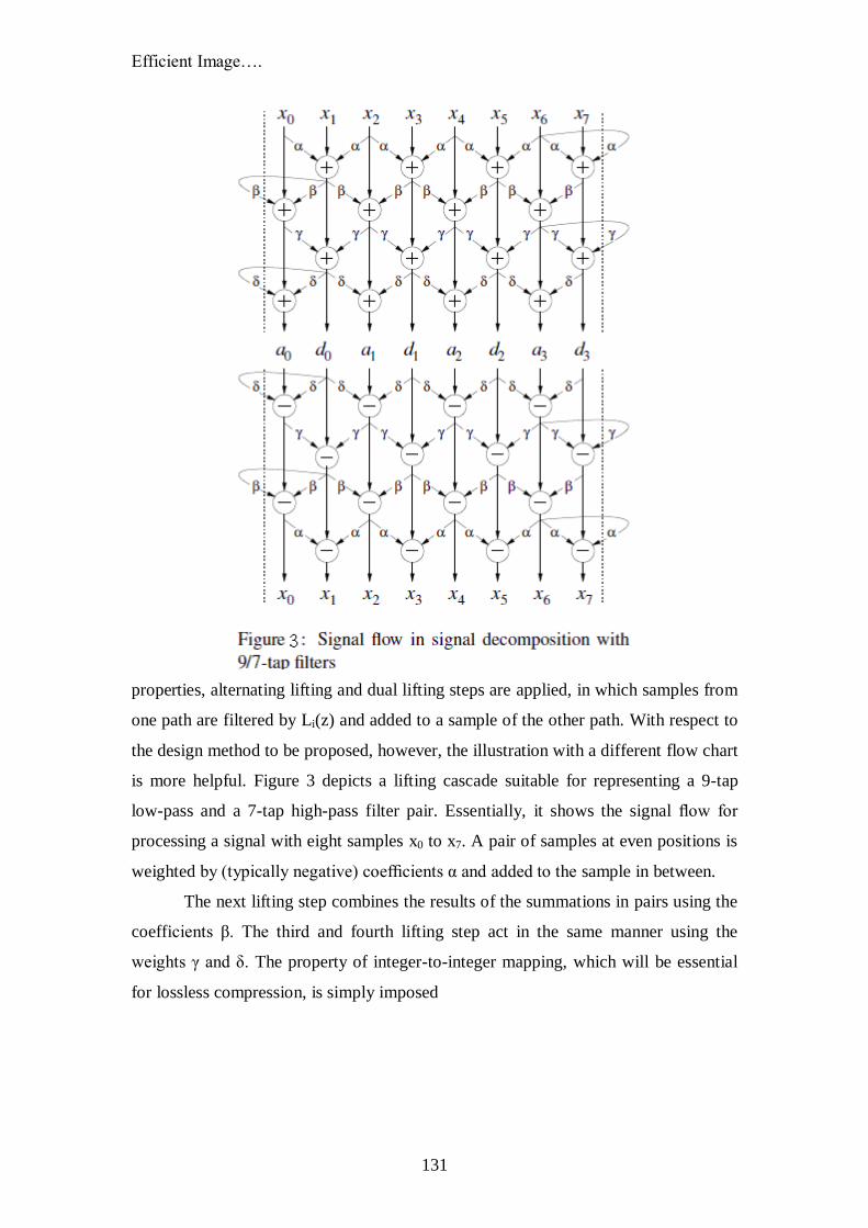
properties, alternating lifting and dual lifting steps are applied, in which samples from
one path are filtered by Li(z) and added to a sample of the other path. With respect to
the design method to be proposed, however, the illustration with a different flow chart
is more helpful. Figure 3 depicts a lifting cascade suitable for representing a 9-tap
low-pass and a 7-tap high-pass filter pair. Essentially, it shows the signal flow for
processing a signal with eight samples x0 to x7. A pair of samples at even positions is
weighted by (typically negative) coefficients α and added to the sample in between.
The next lifting step combines the results of the summations in pairs using the
coefficients β. The third and fourth lifting step act in the same manner using the
weights γ and δ. The property of integer-to-integer mapping, which will be essential
for lossless compression, is simply imposed
G.Chenchu Krishnaiah
132
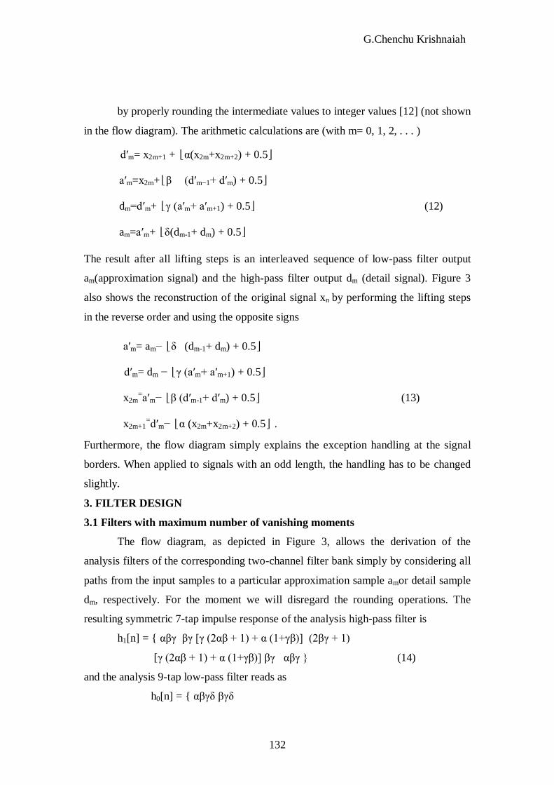
by properly rounding the intermediate values to integer values [12] (not shown
in the flow diagram). The arithmetic calculations are (with m= 0, 1, 2, . . . )
d′m= x2m+1 + ⌊α(x2m+x2m+2) + 0.5⌋
a′m=x2m+⌊β (d′m−1+ d′m) + 0.5⌋
dm=d′m+ ⌊γ (a′m+ a′m+1) + 0.5⌋ (12)
am=a′m+ ⌊δ(dm-1+ dm) + 0.5⌋
The result after all lifting steps is an interleaved sequence of low-pass filter output
am(approximation signal) and the high-pass filter output dm (detail signal). Figure 3
also shows the reconstruction of the original signal xn by performing the lifting steps
in the reverse order and using the opposite signs
a′m= am− ⌊δ (dm-1+ dm) + 0.5⌋
d′m= dm − ⌊γ (a′m+ a′m+1) + 0.5⌋
x2m=a′m− ⌊β (d′m-1+ d′m) + 0.5⌋ (13)
x2m+1=d′m− ⌊α (x2m+x2m+2) + 0.5⌋ .
Furthermore, the flow diagram simply explains the exception handling at the signal
borders. When applied to signals with an odd length, the handling has to be changed
slightly.
3. FILTER DESIGN
3.1 Filters with maximum number of vanishing moments
The flow diagram, as depicted in Figure 3, allows the derivation of the
analysis filters of the corresponding two-channel filter bank simply by considering all
paths from the input samples to a particular approximation sample amor detail sample
dm, respectively. For the moment we will disregard the rounding operations. The
resulting symmetric 7-tap impulse response of the analysis high-pass filter is
h1[n] = { αβγ βγ [γ (2αβ + 1) + α (1+γβ)] (2βγ + 1)
[γ (2αβ + 1) + α (1+γβ)] βγ αβγ } (14)
and the analysis 9-tap low-pass filter reads as
h0[n] = { αβγδ βγδ
Efficient Image….
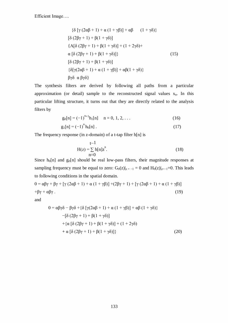
133
{δ [γ (2αβ + 1) + α (1 + γβ)] + αβ (1 + γδ)}
[δ (2βγ + 1) + β(1 + γδ)]
{Α[δ (2βγ + 1) + β(1 + γδ)] + (1 + 2γδ)+
α [δ (2βγ + 1) + β(1 + γδ)]} (15)
[δ (2βγ + 1) + β(1 + γδ)]
{δ[γ(2αβ + 1) + α (1 + γβ)] + αβ(1 + γδ)}
βγδ α βγδ}
The synthesis filters are derived by following all paths from a particular
approximation (or detail) sample to the reconstructed signal values xn. In this
particular lifting structure, it turns out that they are directly related to the analysis
filters by
g0[n] = (−1)n+1
h1[n] n = 0, 1, 2, . . . (16)
g1[n] = (−1)n h0[n] . (17)
The frequency response (in z-domain) of a t-tap filter h[n] is
t−1
H(z) = ∑ h[n]zn. (18)
n=0
Since h0[n] and g0[n] should be real low-pass filters, their magnitude responses at
sampling frequency must be equal to zero: G0(z)|z = −1 = 0 and H0(z)|z=−1=0. This leads
to following conditions in the spatial domain.
0 = αβγ + βγ + [γ (2αβ + 1) + α (1 + γβ)] +(2βγ + 1) + [γ (2αβ + 1) + α (1 + γβ)]
+βγ + αβγ . (19)
and
0 = αβγδ − βγδ +{δ [γ(2αβ + 1) + α (1 + γβ)] + αβ (1 + γδ)}
−[δ (2βγ + 1) + β(1 + γδ)]
+{α [δ (2βγ + 1) + β(1 + γδ)] + (1 + 2γδ)
+ α [δ (2βγ + 1) + β(1 + γδ)]} (20)

G.Chenchu Krishnaiah
134
−[δ (2βγ + 1) + β(1 + γδ)]
+{δ[γ(2αβ + 1) + α (1 + γβ)] + αβ(1 + γδ)}
−βγδ + αβγδ
The original aim of filter design in [13] was to create low-pass filters with frequency
responses that are as flat as possible at sampling frequency by imposing a maximum
number of so-called vanishing moments, i.e. multiple zeros at H0(z)|z=-1and G0(z)|z=-1.
Multiple vanishing moments at z = -1 can be incorporated by substituting z with n√n
p
(p = 0, 1, 2, . . . ) in equation (18). The second zero for G0(z) (and accordingly for
H1(z) at z = 1), for example, is included using z =n√n leading to the condition
0 = 0 αβγ + 1 βγ + 2 [γ (2αβ + 1) + α (1 + γβ)]
+3 (2βγ + 1) + 4 [γ (2αβ + 1) + α (1 + γβ)]
+5 βγ + 6αβγ . (21)
A different interpretation of this approach is based on the approximation of
signal segments by polynomials of increasing order [13]. The condition for the second
zero for H0(z) and G1(z) reads as
0 = 0 αβγδ − 1 βγδ
+2{δ [γ (2αβ + 1) + α (1 + γβ)] + αβ (1 + γδ)}
−3 [δ (2βγ + 1) + β(1 + γδ)] +
4{α [δ (2βγ + 1) + β(1 + γδ)] + (1 + 2γδ) +
α [δ (2βγ + 1) + β (1 + γδ)]}
−5 [δ (2βγ + 1) + β(1 + γδ)]
+6{δ [γ (2αβ + 1) + α (1 + γβ)] + αβ(1 + γδ)}
−7 βγδ + 8 αβγδ . (22)
The conditions (21) and (21) are, however, not independent from (19) and (20). Two
more constraints are necessary for the determination of the four weights α. . . δ.
Choosing z = n√n
2 imposes another vanishing moment. The corresponding conditions
are

Efficient Image….
135
0 = 0 αβγ + 1 βγ + 4 [γ (2αβ + 1) + α (1 + γβ)]
+9 (2βγ + 1) + 16 [γ (2αβ + 1) + α (1 + γβ)]
+25 βγ + 36 αβγ . (23)
0 = 0 αβγδ − 1 βγδ
+4{δ [γ(2αβ + 1) + α (1 + γβ)] + αβ (1 + γδ)}
−9 [δ (2βγ + 1) + β(1 + γδ)] +
16{α [δ (2βγ + 1) + β(1 + γδ)] + (1 + 2γδ) +
α [δ (2βγ + 1) + β (1 + γδ)]}
−25 [δ (2βγ + 1) + β(1 + γδ)]
+36{δ [γ (2αβ + 1) + α (1 + γβ)] + αβ (1 + γδ)}
−49 βγδ + 64 αβγδ . (24)
Equations (21) – (24) form a system of non-linear equations resulting to the irrational
weights
α ≈−1.58613434206
β ≈−0.05298011857
γ ≈ 0.88291107553 (25)
δ ≈ 0.44350685204 .
Due to the inherent structure of the filter bank, each of the conditions impose double
zeros, i.e. each filter shows four vanishing moments in total. The result is exactly the
same as derived from the factorisation of a polyphase matrix presented in [14].
4. DESIGN OF 5/3 WAVELET FILTERS
Setting the factors γ and δ equal to zero shortens the work in signal
decomposition. The lengths of the impulse responses are reduced to 5 taps for the
low-pass filter and 3 taps for the high pass, respectively
0
1
[ ] { (1 2 ) }
[ ] { 1 }
h n
h n
(26)

G.Chenchu Krishnaiah
136
The required conditions are in z-domain
H0(z)|z=-1 = 0
= αβ – β + (1+2 αβ ) - β + αβ
H1(z)|z=1 = 0=α+1+α (27)
Leading to the unique solution of α=-1/2 and β=1/4. This is accordance with the
original solution in [11].
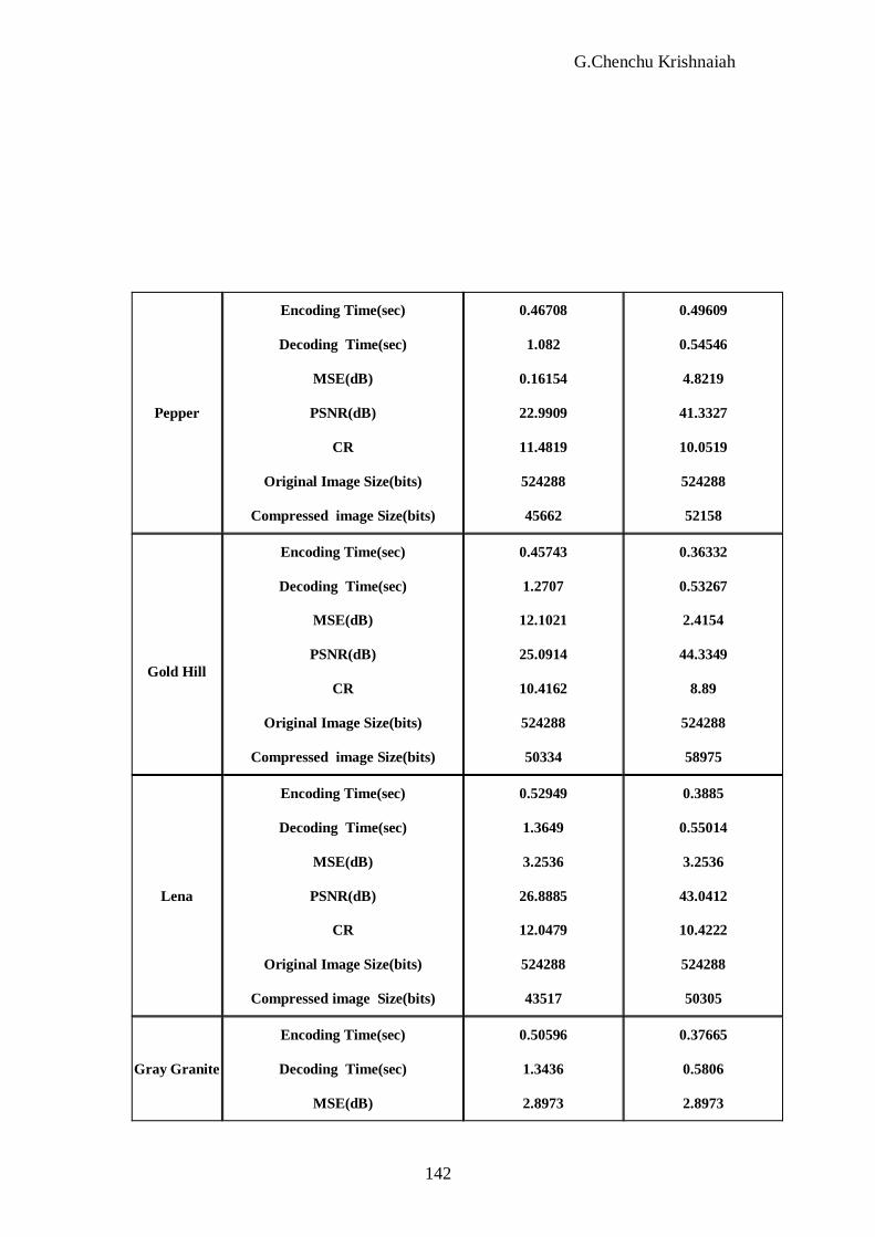
5. SIMULATION RESULTS
The proposed low-complexity architecture has been tested on the standard
images ‘Lena’ 256 x 256 and ‘Barbara’ varying the number of decomposition levels.
The proposed architecture has been employed for the direct transform whereas a
floating point, standard 9/7and 5/3 implementation has been used for the inverse
transform. The values of Peak Signal to Noise Ratio (PSNR), Compression Ratio
(CR), Mean Square Error (MSE), Original image size, Compressed image size,
Encoding time, Decoding time and transforming time or decomposition time were
obtained from the experimental results, and summarized in tables below. The 5/3
filters have lower computational complexicity than the 9/7’s. However the
performance gain of the 9/7’s over the 5/3’s is quite large for JPEG-2000.

Efficient Image….
137
0.3353
0.44641
2.5553
44.0904
11.9717
524288
43794
0.45374
1.0453
0.49863
31.1828
14.2427
524288
36811
Encoding
Time(bits)
Decoding
Time(bits)
MSE(dB)
PSNR(dB)
CR
Original Image
Size(bits)
Bird
0.24723
0.43202
1.8889
45.4028
11.6584
524288
44971
0.46749
1.4128
2.4905
27.8369
13.8906
524288
37744
Encoding
Time(sec)
Decoding
Time(sec)
MSE(dB)
PSNR(dB)
CR
Original Image
Size(bits)
Compressed image
Size(bits)
Rice
0.39729
0.84589
3.263
43.0286
9.724
524288
53917
0.49088
2.0138
2.2291
23.1718
12.1399
524288
43187
Encoding Time
(sec)
Decoding Time
(sec)
MSE(dB)
PSNR (dB)
CR
Original Image
Size(bits)
Compressed image
Size(bits)
Cameraman
5/3-TRANSFORM
9/7-TRANSFORM
PERFORMANCE CRITERION
INPUT IMAGE
PERFORMANCE COMPARISIONS OF 9/7 & 5/3 LIFTING
BASED INTEGER TO INTEGER WAVELET TRANSFORMS

G.Chenchu Krishnaiah
138
SAMPLE GRAPHS:
Figure 1: Encoding time values of 9/7 &5/3 wavelet transforms for
Cameraman image (monochrome)
0
0.1
0.2
0.3
0.4
0.5
0.6
0.7
0.8
0.9
1
9/7t
ransf
orm
5/3
tran
sform
TYPE OF WAVELETS
EN
CO
DIN
G T
IME
(S
EC
)

Efficient Image….
139
Figure 2: Decoding time values of 9/7 &5/3 wavelet transforms for
Cameraman image (monochrome)
0
0.5
1
1.5
2
2.5
9/7t
ransf
orm
5/3
tran
sform
TYPE OF WAVELETS
Deco
din
g
TIM
E (
SE
C )
0
0.5
1
1.5
2
2.5
3
3.5
9/7t
ransf
orm
5/3
tran
sform
TYPE OF WAVELETS
M S
E (
dB
)

G.Chenchu Krishnaiah
140
Figure 4: PSNR values of 9/7 &5/3 wavelet transforms for
Cameraman image (monochrome)
Figure 5: Compression Ratio (CR) values of 9/7 &5/3 wavelet
transforms for Cameraman image (monochrome)
0
10
20
30
40
50
9/7t
rans
form
5/3
tran
sform
TYPE OF WAVELETS
P S
N R
(d
B)
0
1
2
3
4
5
6
7
8
9
10
11
12
13
9/7t
ransf
orm
5/3
tran
sform
TYPE OF WAVELETS
C R
(b
pp
)

Efficient Image….
141
Dog
Encoding Time(sec)
Decoding Time(sec)
MSE(dB)
PSNR(dB)
CR
Original Image Size(bits)
Compressed image Size(bits)
0.51696
1.242
1.1571
27.8874
11.5515
524288
45387
0.43424
0.49488
1.1571
47.5311
9.8587
524288
53180
Barbara
Encoding Time(sec)
Decoding Time(sec)
MSE(dB)
PSNR(dB)
CR
Original Image Size(bits)
Compressed image Size(bits)
0.50847
1.3234
3.263
28.7809
12.4638
524288
42065
0.3646
0.63403
2.4905
44.202
11.6571
524288
44976
Rose
Encoding Time(sec)
Decoding Time(sec)
MSE(dB)
PSNR(dB)
CR
Original Image Size(bits)
Compressed image Size(bits)
0.54101
1.1259
1.8889
28.8329
13.5489
524288
38696
0.36707
0.50336
0.49863
51.187
12.2666
524288
42741
Circuit
Encoding Time(sec)
Decoding Time(sec)
MSE(dB)
PSNR(dB)
CR
Original Image Size (bits)
Compressed image Size(bits)
0.50626
1.2363
0.79579
26.7498
13.8767
524288
37782
0.35049
0.51646
0.79579
49.1568
11.7955
524288
4444
G.Chenchu Krishnaiah
142
Pepper
Encoding Time(sec)
Decoding Time(sec)
MSE(dB)
PSNR(dB)
CR
Original Image Size(bits)
Compressed image Size(bits)
0.46708
1.082
0.16154
22.9909
11.4819
524288
45662
0.49609
0.54546
4.8219
41.3327
10.0519
524288
52158
Gold Hill
Encoding Time(sec)
Decoding Time(sec)
MSE(dB)
PSNR(dB)
CR
Original Image Size(bits)
Compressed image Size(bits)
0.45743
1.2707
12.1021
25.0914
10.4162
524288
50334
0.36332
0.53267
2.4154
44.3349
8.89
524288
58975
Lena
Encoding Time(sec)
Decoding Time(sec)
MSE(dB)
PSNR(dB)
CR
Original Image Size(bits)
Compressed image Size(bits)
0.52949
1.3649
3.2536
26.8885
12.0479
524288
43517
0.3885
0.55014
3.2536
43.0412
10.4222
524288
50305
Gray Granite
Encoding Time(sec)
Decoding Time(sec)
MSE(dB)
0.50596
1.3436
2.8973
0.37665
0.5806
2.8973

Efficient Image….
143
PSNR(dB)
CR
Original Image Size(bits)
Compressed image Size(bits)
29.0242
11.4792
524288
45673
43.5449
10.7858
524288
48609
Circle
Encoding Time(sec)
Decoding Time(sec)
MSE(dB)
PSNR(dB)
CR
Original Image Size(bits)
Compressed image
Size(bits)
0.48915
1.2873
0.79579
23.9129
45.1233
524288
11619
0.44463
0.57181
0.11275
57.6437
32.0117
524288
16378
Hill
Encoding Time(sec)
Decoding Time(sec)
MSE(dB)
PSNR(dB)
CR
Original Image Size(bits)
Compressed image
Size(bits)
0.54289
1.1755
2.8973
23.3348
10.3089
524288
50858
0.45352
0.63435
3.4723
42.7586
8.8802
524288
59040
GKCE Font
Encoding Time(sec)
Decoding Time(sec)
MSE(dB)
PSNR(dB)
CR
0.5161
1.1777
1.1571
19.9739
87.5272
0.36887
0.53379
12.1021
37.3362
19.3094

G.Chenchu Krishnaiah
144
Original Image Size(bits)
Compressed image
Size(bits)
524288
5990
524288
27152
GKCE Logo
Encoding Time(sec)
Decoding Time(sec)
MSE(dB)
PSNR(dB)
CR
Original Image Size(bits)
Compressed image
Size(bits)
0.58224
1.1192
12.1021
24.6747
20.8034
524288
25202
0.43825
0.56097
12.1021
37.3362
12.2744
524288
42714
Bridge
Encoding Time(sec)
Decoding Time(sec)
MSE(dB)
PSNR(dB)
CR
Original Image Size(dB)
Compressed image
Size(dB)
0.40889
1.065
2.5553
28.7507
12.6594
524288
41415
0.32063
0.50548
2.8421
43.6284
10.6565
524288
49199
CONCLUSION
In this paper a low-complexity, efficient 9/7 wavelet filters implementation,
has been derived. A detailed analysis of the proposed solution architectural impact
has been shown with performance and comparisons with the direct implementation.
Efficient Image….
145
We have presented a new biorthogonal 9/7 – tap wavelet with simple
coefficients, so computational complexity is reduced greatly compared to the well-
known CDF 9/7 – tapwavelet. The simulation shows that the new 9/7-tap wavelet is
very ideal alternative to CDF 9/7 – tap wavelet.
The other wavelet transform, 5/3 wavelet is very efficient in lossless
compression and is low complex. From all the above factors, we can conclude that
simple 9/7 and 5/3 wavelet transforms are very efficient than the conventional
wavelets/ traditional wavelets/ hand designed wavelets presently used to compress the
images.
REFERENCES
1. M. Vetterli and J. Kovacevic, Wavelets and Subband Coding,
SignalProcessing, Prentice Hall, Englewood, Cliff. NJ, 1995.
2. D. Taubman, “High performance scalable image compression with EBCOT”,
IEEE Trans. On Image Processing, vol.9, No.7, pp.1158-1170, Jul.2000.
3. A. Said and W.A. PLearlman, “a new, fast, and efficient image codec based on
Set Partitioning In Hierarchical Trees,” IEEE Trans. On Circuits and Systems
for Video Technology, Vol.6, no.3, pp.243-250, Jun.1996.
4. M. Antonini, M. Barlaud, P. Mathieu, and I. Daubechies, “Image coading
using the wavelet transform,” IEEE Tran. On Image Processing, Vo.1, No.2,
,pp.205-220, Apr.1992.
5. J.D. Villasenor, B. Belzer, and J. Liao, “wavelet filter evaluation for image
compression,” IEEE Tran. On Image Processing, Vol.4, No.8, pp.1053-1060,
Aug.1995.
6. M. Boliek, “JPEG 2000 Final Committee Draft,
http://www.jpeg.org/public/fcd15444-1.pdf,” 2000.
7. I. Daubechies and W. Sweldens, “Factoring Wavelet Transforms into Lifting
Steps,: Tech.Rep.Bell Laboratories, Lucent Technologies, 1996.
G.Chenchu Krishnaiah
146
8. C.T. Haung, P.C. Tseng, and L.G. Chen, “Flipping Structure: an efficient
VLSI architecture for liftingbased discrete wavelet transform,” IEEE Tran. On
Signal Processing, vol.52, no.4, pp.1080-1089, Apr.2004.
9. K.A. Kotteri, A.E. Bell, ad J.e. Carletta, “Design of multiplierless, high-
performance, wavelet filter banks with image compression applications,”
IEEE Tran. On Circuits and Systems-I, vol.51, no.3, pp.483-494, Mar.2004.
10. G. Strang and T.Q.Nguyen, Wavelets and Filter Banks, Wellesley, Wellesley-
Combridge, MA, 1996.
11. Sweldens, W; The lifting scheme: A new philosophy in biorthogonal wavelet
construction on proc. Of SPIEE, Vo..2569, Sar Diego, USA, July 1995, 68-79.
12. Calgerbank, A.R.; Daubechies, I.; Sweledens, W.; Yeo, B.L,: Wavelet
Transform that maps integers to integers. Applied Computational and
harmonic analysis, Vol.5, No.3, 1998, 332-369.
13. Strutz, T.: Muller, E.: Wavelet filter design for image compression. IEEE-SP
Int. Symposium on Time-Frequency and Time-scale analysis, Paris, 18-21
June 1996, 273-276.
14. Cohen, A.; Daubechies, I.; Feauveau, J.-C.: Biorthogonal Bases of compactly
supported Wavelets. Comm. On Pure and Applied Mathematics, Vol.45, 1992,
485-560.

Efficient Image….
147