Efficient Hardware Implementation of Hybrid Cosine ...homepage.usask.ca/~sss210/DCT_paper.pdf ·...
4
Efficient Hardware Implementation of Hybrid Cosine- Fourier-Wavelet Transforms on a Single FPGA K. Wahid + , S. Shimu + , M. Islam + , D. Teng + , Moon Ho Lee * , and S-B. Ko *+ + Department of Electrical and Computer Engineering University of Saskatchewan, Saskatoon, Saskatchewan, Canada, S7N5A9 *Institute of Information and Communication, Chonbuk National University, Jeonju 561-756, Korea email: [email protected] Abstract— This paper presents an efficient hardware implementation of a hybrid architecture to compute three 8- point transforms – the Discrete Cosine Transform, the Discrete Fourier Transform, and the Discrete Wavelet Transform on a single FPGA. The architecture is based on an element-wise matrix factorization and row-permutation algorithm, where the forward basis transformation matrices are decomposed into multiple sub-matrices and the common units are shared among them. The hardware implementation is parallel, pipelined and multiplication-free; it costs only 2,073 logic cells, 1,476 registers and runs at maximum frequency of 118 MHz with a very high process throughput of 944 Megabits/sec when synthesized onto an Altera FPGA device. The synthesized results for other FPGA technologies are also presented for performance assessment. I. INTRODUCTION The paradigm of system on chip design techniques has brought an added dimension to multimedia-based applications by allowing third party intellectual property (IP) blocks to be used by digital circuit designers. This provides us with an opportunity to introduce efficient arithmetic techniques into next generation integrated circuits, where we can take advantage of the arithmetic structure to implement faster and area-efficient processors. The Discrete Cosine Transform (DCT) is reportedly the best suboptimal transformation for image and video processing and being used in various coding standards [1]. The Discrete Fourier Transform (DFT) has been widely used as the fundamental computation unit for signal processing and communication applications [2]. Over the past decade, the Discrete Wavelet Transform (DWT) based on the Haar matrix [3] has become very popular for compression algorithms, especially after the DWT’s inclusion in the JPEG2000 standard [4]. Taking the respective strengths and weaknesses of these transforms into account, researchers have developed several new schemes, called hybrid architectures, where these transforms can be combined to achieve better performance. For example, the Fourier-Wavelet transform can be used to improve the denoising performance for images [5]; a Cosine- Wavelet hybrid structure can be used to minimize the prediction errors in video coding [6][7] and to enhance the security in digital watermarking [8], etc. Here in this paper, we present an efficient hardware implementation of a hybrid architecture to compute the three popular 8-point transforms – the DCT, the DFT, and the DWT on a single FPGA. Fig. 1 illustrates the presented hybrid architecture of the DCT-DFT-DWT. The architecture is based on an element-wise matrix factorization and row-permutation algorithm, where the forward basis transformation matrices are first decomposed into multiple sub-matrices; the common structures of the sub-matrices are then identified and shared among them. This results in significant hardware savings in terms of less computational resources, as well as faster design. The architecture has been prototyped onto several FPGA technologies for performance assessment. The implementation details, as well as synthesis results are discussed. Figure 1. Hybrid Cosine-Fourier-Wavelet transform architecture II. MATRIX DECOMPOSITION ALGORITHM In order to decompose the forward transform basis matrices, we utilize sparse matrix factorization where, the DCT, the DFT, and the DWT matrices can be sub-divided into one orthogonal character matrix and a special sparse matrix, named the Jacket matrix [9]. A. Matrix Decomposition of the DCT A classical N-point DCT is defined as follows: 978-1-4244-3828-0/09/$25.00 ©2009 IEEE 2325 Authorized licensed use limited to: University of Saskatchewan. Downloaded on February 24,2010 at 22:25:53 EST from IEEE Xplore. Restrictions apply.
-
Upload
nguyennhan -
Category
Documents
-
view
216 -
download
0
Transcript of Efficient Hardware Implementation of Hybrid Cosine ...homepage.usask.ca/~sss210/DCT_paper.pdf ·...

Efficient Hardware Implementation of Hybrid Cosine-Fourier-Wavelet Transforms on a Single FPGA
K. Wahid+, S. Shimu+, M. Islam+, D. Teng+, Moon Ho Lee*, and S-B. Ko*+ +Department of Electrical and Computer Engineering
University of Saskatchewan, Saskatoon, Saskatchewan, Canada, S7N5A9 *Institute of Information and Communication, Chonbuk National University, Jeonju 561-756, Korea
email: [email protected]
Abstract— This paper presents an efficient hardware implementation of a hybrid architecture to compute three 8-point transforms – the Discrete Cosine Transform, the Discrete Fourier Transform, and the Discrete Wavelet Transform on a single FPGA. The architecture is based on an element-wise matrix factorization and row-permutation algorithm, where the forward basis transformation matrices are decomposed into multiple sub-matrices and the common units are shared among them. The hardware implementation is parallel, pipelined and multiplication-free; it costs only 2,073 logic cells, 1,476 registers and runs at maximum frequency of 118 MHz with a very high process throughput of 944 Megabits/sec when synthesized onto an Altera FPGA device. The synthesized results for other FPGA technologies are also presented for performance assessment.
I. INTRODUCTION The paradigm of system on chip design techniques has
brought an added dimension to multimedia-based applications by allowing third party intellectual property (IP) blocks to be used by digital circuit designers. This provides us with an opportunity to introduce efficient arithmetic techniques into next generation integrated circuits, where we can take advantage of the arithmetic structure to implement faster and area-efficient processors.
The Discrete Cosine Transform (DCT) is reportedly the best suboptimal transformation for image and video processing and being used in various coding standards [1]. The Discrete Fourier Transform (DFT) has been widely used as the fundamental computation unit for signal processing and communication applications [2]. Over the past decade, the Discrete Wavelet Transform (DWT) based on the Haar matrix [3] has become very popular for compression algorithms, especially after the DWT’s inclusion in the JPEG2000 standard [4]. Taking the respective strengths and weaknesses of these transforms into account, researchers have developed several new schemes, called hybrid architectures, where these transforms can be combined to achieve better performance. For example, the Fourier-Wavelet transform can be used to improve the denoising performance for images [5]; a Cosine-Wavelet hybrid structure can be used to minimize the
prediction errors in video coding [6][7] and to enhance the security in digital watermarking [8], etc.
Here in this paper, we present an efficient hardware implementation of a hybrid architecture to compute the three popular 8-point transforms – the DCT, the DFT, and the DWT on a single FPGA. Fig. 1 illustrates the presented hybrid architecture of the DCT-DFT-DWT. The architecture is based on an element-wise matrix factorization and row-permutation algorithm, where the forward basis transformation matrices are first decomposed into multiple sub-matrices; the common structures of the sub-matrices are then identified and shared among them. This results in significant hardware savings in terms of less computational resources, as well as faster design. The architecture has been prototyped onto several FPGA technologies for performance assessment. The implementation details, as well as synthesis results are discussed.
Figure 1. Hybrid Cosine-Fourier-Wavelet transform architecture
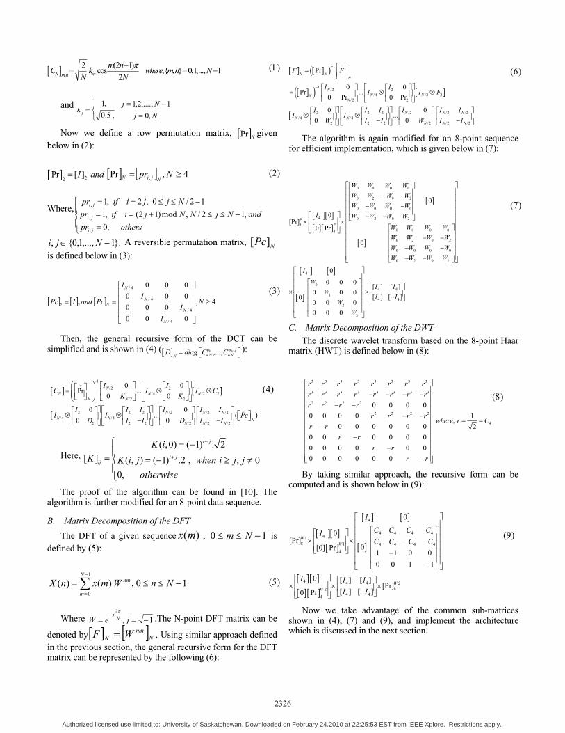
II. MATRIX DECOMPOSITION ALGORITHM In order to decompose the forward transform basis
matrices, we utilize sparse matrix factorization where, the DCT, the DFT, and the DWT matrices can be sub-divided into one orthogonal character matrix and a special sparse matrix, named the Jacket matrix [9].
A. Matrix Decomposition of the DCT A classical N-point DCT is defined as follows:
978-1-4244-3828-0/09/$25.00 ©2009 IEEE 2325
Authorized licensed use limited to: University of Saskatchewan. Downloaded on February 24,2010 at 22:25:53 EST from IEEE Xplore. Restrictions apply.
[ ] ,
2 (2 1)cos ,{ , } 0,1,..., 12N mm n
m nC k where m n NN N
π+= = − (1)
and NjNj
k j ,01,....,2,1
,5.0,1
=−=
⎩⎨⎧
=
Now we define a row permutation matrix, [ ]NPr given below in (2):
[ ] 22Pr [ ]I and= [ ] [ ] 4,Pr , ≥= Npr
NjiN (2)
Where,
⎪⎩
⎪⎨
⎧
=−≤≤+==
−≤≤==
othersprandNjNNjiifpr
Njjiifpr
ji
ji
ji
,0,12/,mod)12(,1
12/0,2,1
,
,
,
}.1,...,1,0{, −∈ Nji A reversible permutation matrix, [ ]NPc is defined below in (3):
[ ] [ ] [ ] 4,
000000
000000
4/
4/
4/
4/
22 ≥
⎥⎥⎥⎥
⎦
⎤
⎢⎢⎢⎢
⎣
⎡
== N
II
II
PcandIPc
N
N
N
N
N
(3)
Then, the general recursive form of the DCT can be simplified and is shown in (4) ([ ] 0 1
4 4,..., NN NN
D diag C Cϕ ϕ −⎡ ⎤= ⎣ ⎦):
[ ] [ ]
[
1~
/2 2/4 /2 2
/2 2
/2 /2 /22 2 2 1/4 /4
/2 /2 /22 2 2
0 0Pr ...
0 0
00... ( )
00
NN N N
N N
N N NN N N
N N N
I IC I I C
K K
I I II I II I Pc
D I ID I I
−
−
⎛ ⎞ ⎡ ⎤⎡ ⎤ ⎡ ⎤⎡ ⎤= ⊗ ⊗⎜ ⎟ ⎢ ⎥⎢ ⎥ ⎢ ⎥⎢ ⎥⎜ ⎟⎣ ⎦ ⎣ ⎦⎣ ⎦ ⎣ ⎦⎝ ⎠⎤ ⎡ ⎤ ⎡ ⎤ ⎡ ⎤⎡ ⎤ ⎡ ⎤ ⎡ ⎤⊗ ⊗⎥ ⎢ ⎥ ⎢ ⎥ ⎢ ⎥⎢ ⎥ ⎢ ⎥ ⎣ ⎦−−⎣ ⎦ ⎣ ⎦ ⎣ ⎦ ⎣ ⎦⎦ ⎣ ⎦
(4)
Here, ( ,0) ( 1) . 2
[ ] ( , ) ( 1) .2 , , 00,
i j
i jij
K iK K i j when i j j
otherwise
+
+
⎧ = −⎪
= ⎨ = − ≥ ≠⎪⎩
The proof of the algorithm can be found in [10]. The algorithm is further modified for an 8-point data sequence.
B. Matrix Decomposition of the DFT The DFT of a given sequence )(mx , 10 −≤≤ Nm is
defined by (5):
1
0( ) ( ) , 0 1
Nnm
mX n x m W n N
−
=
= ≤ ≤ −∑ (5)
Where 1,2
−==−
jeW Nj π
.The N-point DFT matrix can be
denoted by[ ] [ ]Nnm
N WF = . Using similar approach defined in the previous section, the general recursive form for the DFT matrix can be represented by the following (6):
[ ] [ ]( )
[ ]( ) [ ]
[
~1
1/2 2
/4 /2 2/2 2
/2 /2 /22 2 2/4 /4
/2 /2 /22 2 2
Pr
0 0Pr ...
0 Pr 0 Pr
00...
00
N NN
NN NN
N
N N NN N
N N N
F F
I II I F
I I II I II I
W I IW I I
−
−
⎡ ⎤= ⎢ ⎥⎣ ⎦
⎡ ⎤⎡ ⎤ ⎡ ⎤= ⊗ ⊗⎢ ⎥⎢ ⎥ ⎢ ⎥
⎣ ⎦⎣ ⎦ ⎣ ⎦⎤ ⎡ ⎤ ⎡ ⎤ ⎡ ⎤⎡ ⎤ ⎡ ⎤
⊗ ⊗⎥ ⎢ ⎥ ⎢ ⎥ ⎢ ⎥⎢ ⎥ ⎢ ⎥ −−⎣ ⎦ ⎣ ⎦ ⎣ ⎦ ⎣ ⎦⎦ ⎣ ⎦
(6)
The algorithm is again modified for an 8-point sequence for efficient implementation, which is given below in (7):
[ ][ ][ ] [ ]
[ ]
[ ]
[ ] [ ]
[ ]
0 0 0 0
0 2 0 2
0 0 0 0
4 0 2 0 28
0 0 0 04
0 2 0 2
0 0 0 0
0 2 0 2
4
0
1
2
3
0
0[Pr]
0 Pr
0
0
0 0 00 0 0
00 0 00 0 0
FF
W W W WW W W WW W W W
I W W W W
W W W WW W W WW W W WW W W W
I
WW
WW
⎡ ⎤⎡ ⎤⎢ ⎥⎢ ⎥− −⎢ ⎥⎢ ⎥⎢ ⎥⎢ ⎥− −⎢ ⎥⎢ ⎥⎡ ⎤ − −⎣ ⎦⎢ ⎥⎢ ⎥× × ⎢ ⎥⎡ ⎤⎢ ⎥⎣ ⎦ ⎢ ⎥⎢ ⎥⎢ ⎥− −⎢ ⎥⎢ ⎥⎢ ⎥− −⎢ ⎥⎢ ⎥⎢ ⎥− −⎣ ⎦⎣ ⎦
⎡ ⎤⎢ ⎥
⎡ ⎤⎢⎢ ⎥⎢× ⎢ ⎥⎢⎢ ⎥⎢⎢ ⎥⎢⎣ ⎦⎣ ⎦
4 4
4 4
[ ] [ ][ ] [ ]I II I
⎥ ⎡ ⎤⎥ × ⎢ ⎥⎥ −⎣ ⎦⎥⎥
(7)
C. Matrix Decomposition of the DWT The discrete wavelet transform based on the 8-point Haar
matrix (HWT) is defined below in (8):
3 3 3 3 3 3 3 3
3 3 3 3 3 3 3 3
2 2 2 2
2 2 2 2
4
0 0 0 00 0 0 0 1,
0 0 0 0 0 0 20 0 0 0 0 00 0 0 0 0 00 0 0 0 0 0
r r r r r r r rr r r r r r r rr r r r
r r r rwhere r C
r rr r
r rr r
⎡ ⎤⎢ ⎥− − − −⎢ ⎥⎢ ⎥− −⎢ ⎥
− −⎢ ⎥ = =⎢ ⎥−⎢ ⎥
−⎢ ⎥⎢ ⎥−⎢ ⎥⎢ ⎥−⎣ ⎦
(8)
By taking similar approach, the recursive form can be computed and is shown below in (9):
[ ][ ][ ]
[ ] [ ]
[ ]
[ ] [ ][ ] [ ]
4
4 4 4 441
8 1 4 4 4 44
4 4 4 282
4 44
0
0[Pr]
0[0] Pr1 1 0 00 0 1 1
0 [ ] [ ][Pr]
[ ] [ ]0 Pr
WW
WW
I
C C C CIC C C C
I I II I
⎡ ⎤⎢ ⎥
⎡ ⎤⎢ ⎥⎡ ⎤⎢ ⎥⎢ ⎥⎢ ⎥× × − −⎢ ⎥⎢ ⎥⎢ ⎥⎣ ⎦ ⎢ ⎥−⎢ ⎥⎢ ⎥⎢ ⎥−⎣ ⎦⎣ ⎦
⎡ ⎤ ⎡ ⎤⎢ ⎥× × ×⎢ ⎥−⎢ ⎥ ⎣ ⎦⎣ ⎦
(9)
Now we take advantage of the common sub-matrices shown in (4), (7) and (9), and implement the architecture which is discussed in the next section.
2326
Authorized licensed use limited to: University of Saskatchewan. Downloaded on February 24,2010 at 22:25:53 EST from IEEE Xplore. Restrictions apply.
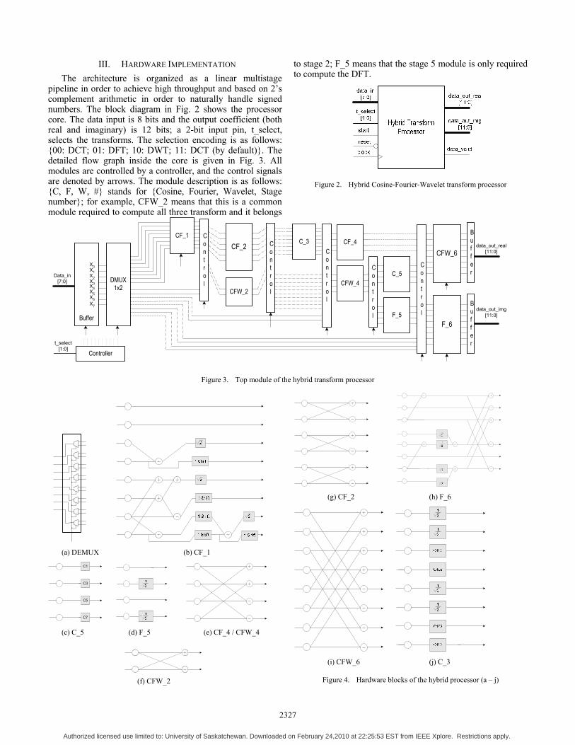
III. HARDWARE IMPLEMENTATION The architecture is organized as a linear multistage
pipeline in order to achieve high throughput and based on 2’s complement arithmetic in order to naturally handle signed numbers. The block diagram in Fig. 2 shows the processor core. The data input is 8 bits and the output coefficient (both real and imaginary) is 12 bits; a 2-bit input pin, t_select, selects the transforms. The selection encoding is as follows: {00: DCT; 01: DFT; 10: DWT; 11: DCT (by default)}. The detailed flow graph inside the core is given in Fig. 3. All modules are controlled by a controller, and the control signals are denoted by arrows. The module description is as follows: {C, F, W, #} stands for {Cosine, Fourier, Wavelet, Stage number}; for example, CFW_2 means that this is a common module required to compute all three transform and it belongs
to stage 2; F_5 means that the stage 5 module is only required to compute the DFT.
Figure 2. Hybrid Cosine-Fourier-Wavelet transform processor
Buffer
CF_1C_3
C_5
CF_2 CF_4
CFW_4
F_5
DMUX1x2X5
X6X7
X2X3X4
X0X1
CFW_2
Control
Control
Control
Control
Control
CFW_6
Data_in[7:0]
F_6
Buffer
Buffer
data_out_real[11:0]
data_out_img[11:0]
Controllert_select
[1:0]
Figure 3. Top module of the hybrid transform processor
(a) DEMUX (b) CF_1
C3
C1
C7
C5
(c) C_5 (d) F_5 (e) CF_4 / CFW_4
(g) CF_2 (h) F_6
(i) CFW_6 (j) C_3
Figure 4. Hardware blocks of the hybrid processor (a – j) (f) CFW_2
2327
Authorized licensed use limited to: University of Saskatchewan. Downloaded on February 24,2010 at 22:25:53 EST from IEEE Xplore. Restrictions apply.
By asserting high to the “start” pin will start the processor. A high in the “data_valid” pin indicates the valid output coefficients. The intermediate data that come out from the blocks with a control arrow pin have been latched into register banks. Thus from Fig. 3, we can see that a large number of blocks can be shared among the transforms, which results in smaller hardware, as well as lower power consumption.
The internal circuitry of each module has been shown in Fig. 4. Internal counters are set to automatically control these operations and maintain a parallel and congestion-free data flow. The transform coefficients are denoted by small boxes where, cos
16KkC π
= .
These multipliers are fixed in nature; hence, they have been computed with shifts and additions only with a precision of 8 bits as a way to minimize the hardware and optimize the operations, which are completed in one clock cycle. Internally to the multiplier, all significant bits are used to retain the precision of the calculation but the multiplier outputs are truncated to discard the fractional part.
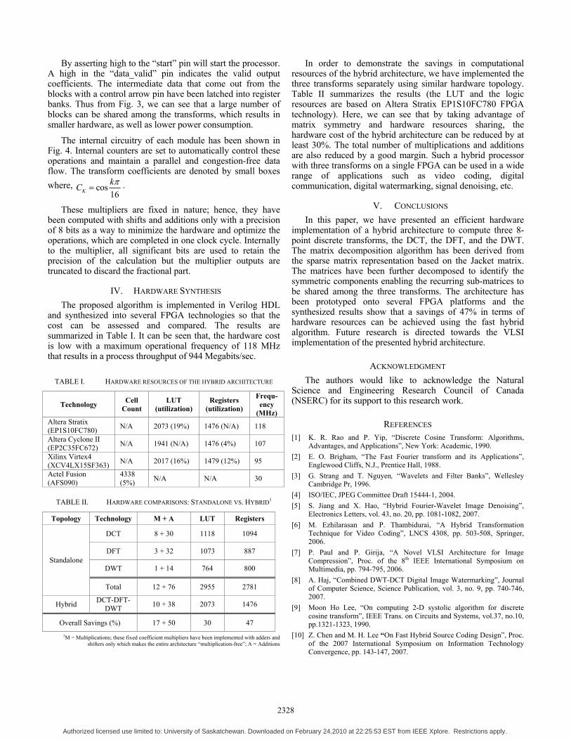
IV. HARDWARE SYNTHESIS The proposed algorithm is implemented in Verilog HDL
and synthesized into several FPGA technologies so that the cost can be assessed and compared. The results are summarized in Table I. It can be seen that, the hardware cost is low with a maximum operational frequency of 118 MHz that results in a process throughput of 944 Megabits/sec.
TABLE I. HARDWARE RESOURCES OF THE HYBRID ARCHITECTURE
Technology Cell Count
LUT (utilization)
Registers (utilization)
Frequ-ency
(MHz) Altera Stratix (EP1S10FC780) N/A 2073 (19%) 1476 (N/A) 118
Altera Cyclone II (EP2C35FC672) N/A 1941 (N/A) 1476 (4%) 107
Xilinx Virtex4 (XCV4LX15SF363) N/A 2017 (16%) 1479 (12%) 95
Actel Fusion (AFS090)
4338 (5%) N/A N/A 30
TABLE II. HARDWARE COMPARISONS: STANDALONE VS. HYBRID1
Topology Technology M + A LUT Registers
DCT 8 + 30 1118 1094
DFT 3 + 32 1073 887
DWT 1 + 14 764 800 Standalone
Total 12 + 76 2955 2781
Hybrid DCT-DFT-DWT 10 + 38 2073 1476
Overall Savings (%) 17 + 50 30 47 1M = Multiplications; these fixed coefficient multipliers have been implemented with adders and
shifters only which makes the entire architecture “multiplication-free”; A = Additions
In order to demonstrate the savings in computational resources of the hybrid architecture, we have implemented the three transforms separately using similar hardware topology. Table II summarizes the results (the LUT and the logic resources are based on Altera Stratix EP1S10FC780 FPGA technology). Here, we can see that by taking advantage of matrix symmetry and hardware resources sharing, the hardware cost of the hybrid architecture can be reduced by at least 30%. The total number of multiplications and additions are also reduced by a good margin. Such a hybrid processor with three transforms on a single FPGA can be used in a wide range of applications such as video coding, digital communication, digital watermarking, signal denoising, etc.
V. CONCLUSIONS In this paper, we have presented an efficient hardware
implementation of a hybrid architecture to compute three 8-point discrete transforms, the DCT, the DFT, and the DWT. The matrix decomposition algorithm has been derived from the sparse matrix representation based on the Jacket matrix. The matrices have been further decomposed to identify the symmetric components enabling the recurring sub-matrices to be shared among the three transforms. The architecture has been prototyped onto several FPGA platforms and the synthesized results show that a savings of 47% in terms of hardware resources can be achieved using the fast hybrid algorithm. Future research is directed towards the VLSI implementation of the presented hybrid architecture.
ACKNOWLEDGMENT The authors would like to acknowledge the Natural
Science and Engineering Research Council of Canada (NSERC) for its support to this research work.
REFERENCES [1] K. R. Rao and P. Yip, “Discrete Cosine Transform: Algorithms,
Advantages, and Applications”, New York: Academic, 1990. [2] E. O. Brigham, “The Fast Fourier transform and its Applications”,
Englewood Cliffs, N.J., Prentice Hall, 1988. [3] G. Strang and T. Nguyen, “Wavelets and Filter Banks”, Wellesley
Cambridge Pr, 1996. [4] ISO/IEC, JPEG Committee Draft 15444-1, 2004. [5] S. Jiang and X. Hao, “Hybrid Fourier-Wavelet Image Denoising”,
Electronics Letters, vol. 43, no. 20, pp. 1081-1082, 2007. [6] M. Ezhilarasan and P. Thambidurai, “A Hybrid Transformation
Technique for Video Coding”, LNCS 4308, pp. 503-508, Springer, 2006.
[7] P. Paul and P. Girija, “A Novel VLSI Architecture for Image Compression”, Proc. of the 8th IEEE International Symposium on Multimedia, pp. 794-795, 2006.
[8] A. Haj, “Combined DWT-DCT Digital Image Watermarking”, Journal of Computer Science, Science Publication, vol. 3, no. 9, pp. 740-746, 2007.
[9] Moon Ho Lee, “On computing 2-D systolic algorithm for discrete cosine transform”, IEEE Trans. on Circuits and Systems, vol.37, no.10, pp.1321-1323, 1990.
[10] Z. Chen and M. H. Lee “On Fast Hybrid Source Coding Design”, Proc. of the 2007 International Symposium on Information Technology Convergence, pp. 143-147, 2007.
2328
Authorized licensed use limited to: University of Saskatchewan. Downloaded on February 24,2010 at 22:25:53 EST from IEEE Xplore. Restrictions apply.