Efficient electro-optic polymers for THz applicationshayden/Pubs/eff EO THz polymers rev1.pdf · 1...
28
1 Efficient electro-optic polymers for THz applications Alexander M.Sinyukov and L.Michael Hayden* Department of Physics, University of Maryland, Baltimore County, Baltimore, MD 21250 Abstract We present a method for producing electro-optic (EO) polymer films with EO coefficients 40-50 pm/V at 785 nm which are suitable for use as emitters and sensors of THz radiation. Direct comparison with ZnTe shows that our EO polymers are more efficient THz emitters than ZnTe. The THz field generated from a 80 μm thick poled polymer film is equal to that generated from a 1 mm thick ZnTe crystal. A model for the THz generation via optical rectification from a poled polymer has been developed and verified experimentally in a THz system using a polymer emitter and a ZnTe sensor. *[email protected]
Transcript of Efficient electro-optic polymers for THz applicationshayden/Pubs/eff EO THz polymers rev1.pdf · 1...

1
Efficient electro-optic polymers for THz applications
Alexander M.Sinyukov and L.Michael Hayden*
Department of Physics, University of Maryland, Baltimore County, Baltimore, MD 21250
Abstract
We present a method for producing electro-optic (EO) polymer films with EO coefficients
40-50 pm/V at 785 nm which are suitable for use as emitters and sensors of THz radiation.
Direct comparison with ZnTe shows that our EO polymers are more efficient THz emitters
than ZnTe. The THz field generated from a 80 µm thick poled polymer film is equal to that
generated from a 1 mm thick ZnTe crystal. A model for the THz generation via optical
rectification from a poled polymer has been developed and verified experimentally in a THz
system using a polymer emitter and a ZnTe sensor.

2
Introduction
During the last 10 years THz radiation has found many applications in industry
and science, attracting high interest to this area. Due to their long wavelength (100-
300 µm), THz waves propagate easily through non-polar, non-metallic material such as
paper, card board and plastic. If an object is inserted in a THz beam, a THz image can be
obtained. In contrast with X-rays, THz radiation is non-ionizing. This advantage allows
T-ray imaging to be a powerful diagnostic tool in medicine and biology.1-3 T-ray
imaging can be also used for food and package inspection and industrial quality
control.4,5 Other applications of THz waves include trace gas analysis, flame emissions,6
impulse ranging,7,8 and THz-interferometry.9
When a THz wave passes through an object, information about the object’s
dielectric properties can be obtained. This is the basis of THz time-domain spectroscopy
(THz-TDS). By comparing changes in the amplitude and phase of the THz electric field
of a signal pulse, recorded when the sample is in the THz beam path, and a reference
pulse, obtained without the sample, detailed, frequency dependent information about the
absorption coefficient and refractive index of the material under study may be
obtained.10-14
Sensitivity, signal to noise ratio, and frequency response are the factors of
primary importance for all the THz applications above. These factors depend on the
THz emitters and detectors used.
Among the many ways to emit and detect THz radiation already tested, coherent
THz systems with photoconductive dipole antennas11 and EO materials15 as THz emitters

3
and detectors are widely used today. EO materials include inorganic and organic crystals
and EO polymers. While crystals (inorganic ZnTe16 GaAs17, GaP18, and organic DAST19
and MBANP20) are widely used in THz experiments, EO polymers have been
comparatively less explored in this regard. Only a small number of papers using EO
polymers have been published.21-25
The goal of this paper is to highlight the properties of EO polymers that make
them attractive for THz applications. In addition, we make direct comparisons of the
THz performance of our EO polymers and the most widely used crystal, ZnTe, which
demonstrate that EO polymers are efficient and promising THz emitters and detectors due
to their larger EO coefficients and longer coherence lengths.
This paper is organized as follows. First, we describe the materials we are
working with and the THz experiment used to test these materials. Then, we present a
model developed for a system of an EO polymer emitter and ZnTe detector.
Experimental verification of this model and other THz results with EO polymers are then
given. Finally, we compare the coherence length of crystals and our polymers. In the
conclusion we summarize our study and discuss future experiments.
Materials
We are working with guest-host polymer composites. They have two
components, a guest-chromophore and a polymer matrix host. Our chromophores
possess large dipole moments (Figure 1), allowing easy orientation in an external electric
field. Various polymer matrices like PMMA, polystyrene, polycarbonate, and APC

4
(poly(bisphenol A carbonate-co-4,4’-(3,3,5-trimethylcyclohexylidene)diphenol
carbonate)) can be used as hosts.
O
N
O
O
C
N
N
C
C
N
N
O
N
C
C
N
C
N
Lemke DCDHF-MOE-V DCDHF-6-Vµ =8.31 Debye, µ = 12.3 Debye, µ = 12.7 Debye,
FOM = 1.9 x Lemke FOM = 1.7 x Lemke
Figure 1. Chromophores and corresponding dipole moments µ and
figures of merit (FOM = µβ/Μ, where β is the hyperpolarizability of the
chromophore and M is the molecular mass).
There is always a trade off between the concentration of the chromophore and the
thermal stability of the EO composite. Increasing the amount of chromophore in the
composite causes an increase of the EO coefficient (eq.1). This is a reason to increase the
concentration of chromophores as much as possible until phase separation (or
crystallization) is observed. On the other hand, increased chromophore concentration
leads to a decrease of the glass transition temperature (Tg) of the composite because the
chromophore acts as a plasticizer for the polymer host. Therefore, in general, the higher
the initial Tg of the polymer host the higher will be the eventual Tg of the composite. In
turn, the higher the Tg of the composite the more stable the polar order of the
chromophores.
We initially worked with a composite of 25% Lemke (2-(3-(2-(4-
dialkylaminophenyl)vinyl)-5,5-dimethylcyclohex-2-enylidene)malononitrile) and 75%
PMMA. This composite, described earlier,24 had a Tg ∼ 850C. More recently, we
obtained better results by using chromophores with a stronger acceptor,
N
NCCN

5
dicyanodihydrofurane (DCDHF)25. The THz experimental results presented in this paper
correspond to composites of 40% DCDHF-6-V/60% APC and 20% DCDHF-6-V/20%
DCDHF-MOE-V/60% APC. These composites have a Tg ∼ 970C. They are better than
the Lemke composite in both their EO and THz performance and in their stability. We
did not observe a significant degradation of the THz performance of our EO polymers
over a period of a couple of weeks.
The preparation of our materials has been described earlier.25 Briefly, films are
cast from solution onto an indium tin oxide (ITO) coated glass substrate. After solvent
evaporation, the solid polymer film is pressed in vacuum at Tg + 700C for 10-15 min. The
thickness of the resulting film is controlled by appropriate polyimide spacers. We can
make films with thicknesses controlled in the range of 50-350 µm, but mostly we worked
with 70-130 µm thick layers.
Initially, the chromophores inside the polymer layer are oriented randomly. The
medium is centrosymmetric, so the 2nd-order nonlinear optical susceptibility is zero.
However a nonzero χ(2) is required for nonlinear interactions such as optical rectification
and electro-optic sensing (discussed in detail in the coming sections). In order to impart a
polar order to the film, high voltage is applied to the ITO electrodes and the sample is
heated up to the glass transition temperature of the composite allowing the chromophores
to orient in the electric field. The sample is then cooled down to room temperature with
the external electric field still applied, to freeze in the orientation of the chromophores,
resulting in a nonzero χ(2) at room temperature without an external field.
Thermal vibrations tend to randomize the orientation of the chromophores.
Therefore, the poling state of the chromophores degrades with time. The higher the Tg of

6
the composite the more stable the nonlinearity. In the weak field approximation the
electro-optic coefficient is directly proportional to the poling field,26
€
r33 =2N5
ε(n2 + 2)2
3n2(n2 + 2ε)
2
βzzzµEp
kT, (1)
where N is the number density of chromophores, ε is the static dielectric constant,
n is the material refractive index, βzzz is the 2nd order polarizability, µ is the molecular
dipole moment, k is Boltzman’s constant, T is the absolute temperature, and Ep is the
poling field. Our experimental results indicate a linear dependence (Figure 2) of r33 on
the poling field. The EO coefficient is also directly proportional to the dipole moment µ
and hyperpolarizability β of the chromophores. In Figure 2, we can see that for the same
70
60
50
40
30
20
10
0Elec
tro-o
ptic
coef
ficie
nt (p
m/V
)
160140120100806040200Poling field (V/µm)
DCDHF-6-V DCDHF-6-V/DCDHF-MOE-V Lemke
ZnTe
Figure 2. Electro-optic coefficient at 785 nm as a function of the poling
field for composites with 40%Lemke, 40%DCDHF-6-V and
20%DCDHF-6-V/20%DCDHF-MOE-V mixed with 60% APC. Solid
lines are a fit to the linear function. For comparison, the EO coefficient of
ZnTe (4 pm/V at 800 nm) is also shown.

7
poling field, the DCDHF-6-V chromophore has a larger EO coefficient than Lemke
because the latter has a lower dipole moment and β.25 For our typical poling field of 80-
100 V/µm, the EO polymer composites have EO coefficients about one order of
magnitude larger than ZnTe.
The plot in Fig.2 was obtained using EO polymer layers 70-130 µm thick.
Thicker layers (>300 µm) have been prepared but lower EO coefficients (about 20 pm/V)
are obtained due to the inability to apply sufficiently high voltages. It is technically
difficult to apply more than ∼12,000 V in our current apparatus. However, there seem to
be no physical limitations to the poling of polymers to achieve the same high EO
coefficients (>50 pm/V) with thick layers.
THz experiment
Optical rectification (OR)27 is widely used to generate THz radiation in EO
materials. In this scheme, short laser pulses (10-200 fs) pump the nonlinear medium.
These pulses contain a range of frequencies. When these frequencies are present inside
the nonlinear medium, difference frequency mixing results in the generation of
broadband radiation in the THz regime.28
In order to test our materials, we use a standard THz generation and detection
scheme (Figure 3). The laser beam from an amplified femtosecond laser (Spectra Physics
SpitFire; 45 fs, 30 µJ/pulse, 800 nm, 1 kHz) is split by a 5 µm pellicle beam splitter into
pump and probe beams. The pump beam is incident on the polymer or crystal emitter
which is located at the focus of the first off-axis parabolic mirror. The generated THz
field is collimated and focused onto the ZnTe sensor by the pair of off-axis parabolic

8
mirrors. A 5 mm thick high density polyethylene disk or 10 mm polystyrene foam,
which is transparent to the THz wave but absorbs the optical beam, is placed after the
emitter to block the residual pump beam. The linear EO effect29 is used to detect the THz
wave. When a linearly polarized probe beam is incident on the detecting crystal without
Figure 3. Experimental set up. P is a polarizer, W is a Wollaston prism,
M is a mirror, PBS is a 5 µm pellicle beam splitter, OAPM is an off-axis
parabolic mirror, λ/2 and λ/4 are half and quarter waveplates. The data
acquisition system consists of a lock-in amplifier which acquires the signal
from balanced photodiodes. A reference signal for the lock-in amplifier is
obtained from a chopper operating at 300-1500 Hz.
a THz field, its polarization is not altered. The balanced detector (2 photodiodes
connected oppositely) shows no signal at this time; both channels give the same current
with opposite polarity. The electric field from an incident THz wave changes the probe
beam’s polarization via the EO effect, which causes a different amount of light to reach
each photodiode. This change is detected by a lock-in amplifier. The probe pulse
Balanceddetector
Data acquisition system
<50 fs, 800 nm, 30 µJ/pulse1 kHz
probe beam
pump beam
Polymeremitter
PBS
Chopper
W λ/4
λ/2
P
λ/2
P
Delay stage
M
M
M
M
M
PBS
Block
<110> ZnTesensor
OAPM
OAPM

9
duration (50 fs) is much smaller than the THz period (1 ps). Therefore, movement of the
computer controlled delay stage changes the time delay between the pump and the probe
pulses and allows the temporal dependence of the THz electric field to be sampled with
the resolution of the probe pulse.
THz generation via optical rectification with EO polymers
In this section, we present a simple model of the THz field generated from a poled
polymer layer and detected with a ZnTe crystal. The purpose of this model is to
illuminate the general features of THz generation in poled polymers.
A poled polymer is in the material class ∞mm. Choosing the Z-axis parallel to
the poling electric field, the nonlinear susceptibility tensor of the polymer (in the polymer
frame) is ,
€
dijk = dil =
0 0 0 0 d15 00 0 0 d15 0 0d31 d31 d33 0 0 0
. (2)
In the laboratory frame, X′Y′Z′, (Figure 4), the incident pump beam propagating in the Z′
direction, has the components
€
E ′ X = E0 cosθ ,E ′ Y = −E0 sinθ ,E ′ Z = 0,
(3)
where E0 is the pump field amplitude and θ is the angle between the X′ axis and the
pump beam polarization (X′Y′ plane is shown at the top of Figure 4). After refraction at

10
the air-glass and glass-polymer interfaces the pump field has the components (in the
polymer frame),
€
EX = EX 'tsAGtsGP = Eo (tsAGtsGP )cosθ
EY = −EY 't pAGt pGP cosζ = E0 (t pAGt pGP )sinθ 1− sin2αn p2
EZ = EY 't pAGt pGP sinζ = E0 (t pAGt pGP )sinθsinαn p
(4)
where ζ is the angle of the pump beam propagation angle inside the polymer layer with
refractive index np, and tsAG, tpAG, tsGP, tpGP are the Fresnel transmission coefficients for
the s- and p-polarizations at the air-glass (AG) and glass-polymer (GP) interfaces, and α
is the angle of incidence.
Figure 4. Optical pump beam incident on the polymer layer on the glass
substrate, α is the angle of incidence, β and ζ are the pump beam
propagation angles in the substrate and polymer layer respectively. X′Y′Z′
is the laboratory frame, XYZ is the polymer frame. ng and np are therefractive indices of the glass substrate and polymer layer respectively.
The pump field in the X′Y′ plane of the laboratory frame is shown at the
top of the figure.
€
α€
α
€
β
€
ζ
€
ng
€
n p
€
Z
€
YGlass substrate
Polymer layer
Laboratory frame
€
′ Y €
′ Z €
E pump
€
′ Y €
′ Z
€
α
Polymer frame
€
θ
€
E pump
€
′ X
€
′ Y

11
The nonlinear polarization induced inside the polymer will have the components,27
€
PXPYPZ
=
0 0 0 0 d15 00 0 0 d15 0 0d31 d31 d33 0 0 0
EXEX
EY EY
EZEZ
2EY EZ
2EXEZ
2EXEY
(5)
and can therefore be written as follows,
€
PX (θ ,α ) = 2d15EXEZ = 2d15E02 (t pAGt pGPtsAGtsGP )sinθ cosθ sinα
n p
,
PY (θ ,α ) = 2d15EZEY = 2d15E02 (t pAGt pGP )2 sin 2θ
sinα n p2 −sin 2α
n p2 ,
PZ (θ ,α ) = d31 (EX2 +EY
2 ) + d33EZ2 = d31E0
2{cos2θ (tsAGtsGP )2 +
+sin 2θ (t pAGt pGP )2 (1− sin 2α
n p2 )} + d33E0
2 sin 2θ (t pAGt pGP )2 sin 2α
n p2 .
(6)
Neglecting birefringence of the medium, we assume that the amplitude of the
generated THz field is directly proportional to the induced nonlinear polarization, ETHz∝
PNL. This simplified approach allows us to easily obtain the formula for the THz field
and to model the system of an EO polymer emitter and a ZnTe detector. As will be
shown in the next section, this model corresponds to the experimental results and gives
the correct behavior for both the amplitude and the polarization of the THz field
generated from a poled polymer. An exact model of THz generation from a poled
polymer based on the solution of the nonlinear wave equation will be presented
elsewhere30.
After refraction at the polymer-air interface the THz electric field in the lab frame
will have the components,

12
€
E ′ X THz (θ ,α )= AtsPAPX (θ ,α ),
E ′ Y THz (θ ,α )= Bt pPA PY
2 (θ ,α )+ PZ2 (θ ,α ),
E ′ Z THz (θ ,α )= 0.
(7)
where A and B are constants and tsPA and tpPA are the Fresnel coefficients at the polymer-
air interface for s- and p-polarizations.
The transmitted THz electric field amplitude in the lab frame is given by,
€
ETHz(θ,α) = EXTHz (θ,α)( )
2+ EY
THz(θ,α)( )2
+ EZTHz (θ,α)( )
2. (8)
If we define the THz polarization angle γ as the angle between the THz electric field
vector and the –Y' axis in the lab frame, then
€
sinγ(θ,α) =EXTHz (θ,α)
ETHz (θ,α)=
tsPA APX (θ,α)tsPA APX (θ,α)( )2 + tpPA
2 B2 PY2(θ,α) + PZ
2(θ,α)( ). (9)
THz detection with a ZnTe crystal has been studied in detail by Planken et al. They find that
the signal intensity due to the linear EO effect in ZnTe is given by the expression,16
€
I signal (θ ,α )= I probeωn 3r41L2c
ETHz (θ ,α )[cosγ (θ ,α )sin 2φ + 2sinγ (θ ,α )cos2φ ] (10)
where Iprobe is the probe beam intensity, ω is the optical frequency, r41 is the EO coefficient of
ZnTe at the probe wavelength, n is the refractive index of ZnTe at the probe wavelength, L is
the crystal thickness, φ is the angle between the probe beam polarization and the (001)
direction of the crystal, and γ is the angle between THz field polarization and the (001)
direction of the crystal in the crystal surface plane (Figure 5).

13
Figure 5. Detection geometry for a <110> ZnTe sensor. Eprobe and ETHz
are the probe and THz electric field vectors, respectively and φ and γ are
their respective polarization angles in the crystal surface plane.
Using the angular dependence of the THz amplitude ETHz(θ,α) (eq.8) and the THz
polarization angle γ(θ,α) (eq.9) in eq.10 gives the dependence of the detected signal as a
function of the pump polarization angle θ for any probe beam angle φ.
THz performance of polymers
In order to confirm our model of THz generation in a poled polymer via optical
rectification, we experimentally determined the angular dependence of the detected THz
signal as a function of the pump beam polarization for probe beam polarizations of 450
and 00. The data is shown in Figure 6 along with a fit to eq.10. The data was obtained by
fixing the delay stage at the position corresponding to the maximum of the THz field
while rotating the pump beam polarization. The angle of incidence was near 560 which
corresponds to the Brewster angle for glass. The maximum amplitude of the generated
(001)
(100) (010)
ETHzEprobeγφ
14
Figure 6. Angular dependence of the THz signal as a function of the pump
polarization angle for two probe beam angles. Solid lines are calculated by eq.10.
THz field for the 450 polarized probe beam corresponds to p-polarization (θ=900) of the
pump beam just as for second harmonic generation in poled polymers.
Figure 7 shows a direct comparison of a ZnTe crystal and polymer emitters.
1.2
1.0
0.8
0.6
0.4
0.2
0.0
-0.2
-0.4
-0.6
Bala
nced
det
ecto
r sig
nal (
nA)
121086420Delay time (ps)
80 µm polymer 1 mm ZnTe
0.0001
0.001
0.01
0.1
Ampl
itude
(a.u
.)
876543210THz
80 µm polymer 1 mm ZnTe
Figure 7. Comparison of the THz field emitted from a 1 mm ZnTe crystal
and an 80 µm polymer layer (40%DCDHF-6-V/60%APC). The EOcoefficient of the polymer is 47±2 pm/V. A 2 mm thick ZnTe sensor is
used in both cases. Temporal traces (left), and corresponding Fourier
transforms (right).
14012010080604020
0-20TH
z pe
ak s
igna
l (nA
)36031527022518013590450
Pump polarization angle (deg)
Probe beam 45°polarization 0°

15
Comparing the peak to peak detected signal, we see that the THz field emitted from the
80 µm EO polymer film is equal to that emitted from the 1 mm ZnTe crystal. Signal to
noise (SNR) in this experiment is about 100. Unfortunately, the damage threshold of our
current materials is lower than that of crystals. For this reason we cannot illuminate the
emitter with the whole power available from the laser system or focus the pump beam
tightly, resulting in a lower SNR. The pump power used in this comparison was 3 mW in
∼0.5 mm spot.
It is necessary to specify the conditions of this comparison. The ZnTe sensor
orientation was kept the same for both polymer and ZnTe emitters. The probe beam
polarization was perpendicular to the plane of incidence (POI) and parallel to the z-axis
of the ZnTe sensor so that φ = 0º in eq.10. This means that the maximum signal is
obtained with the THz field polarization is parallel to the POI for which γ = 90º in eq.10.
This kind of THz field is generated from the polymer layer when the pump beam
polarization is parallel to the POI (p-polarized for the polymer emitter). In contrast, in
order to get the same polarization of THz field from the ZnTe emitter, the pump beam
must be polarized perpendicular to the POI and the crystal z-axis must be parallel to the
POI, so the angle between the pump beam polarization and the emitter z-axis is 90º.15
This combination of the polarization of the pump beam and the orientation of the emitter
gives the maximum THz signal when the ZnTe sensor is oriented as described above.
About 15% more THz power can be obtained from the crystal when the angle between z-
axis of crystal and the pump beam is 55º.15 However, in this case the THz field
polarization is no longer parallel to the POI, requiring a reorientation of the ZnTe sensor.

16
We elected to retain a fixed and common sensor orientation and detection optics
alignment for comparison of emitters.
Previously, Nahata et al.21 reported a 4 times smaller THz amplitude from a 16 µm
thick EO polymer compared to that from a 1 mm thick crystal of LiNbO3. Carrig31
reported that DAST is 11 times better that LiNbO3 for similar thicknesses. Han32 reported
the THz amplitude from 100 µm of DAST to be 6 times larger than that from 30 µm of
ZnTe. Thus, we estimate that 1 mm of ZnTe should be about 20 times better than the 16
µm film of Nahata’s group. Also, Carey et al.20 demonstrated that 200 µm of the organic
crystal MBANP gives 2.5 times better THz signal than 500 µm of ZnTe. This means that
80 µm of our EO polymer gives about the same THz amplitude as obtained from 200 µm
of MBANP or 500 µm of DAST. For all these comparisons, the dependence of the
generated THz field amplitude vs the emitter thickness is assumed to be linear.
800600400200
0-200-400-600
Bala
nced
det
ecto
r sig
nal (
pA)
86420Delay time (ps)
100fV2
46
1pV2
46
10pV2
46
100pV
Ampl
itude
(a.u
.)
876543210THz
Figure 8. THz signal from a pair of EO polymers used as both an emitter
and a sensor of THz radiation (left). A 130 µm single layer of
20%DCDHF-6-V/20%DCDHF-MOE-V/60%APC with an EO coefficient
of 40 pm/V was used. THz spectrum of this pulse (right). This
experiment is performed in the open air. Several strong absorptions due to
water vapor are evident.

17
Figure 8 shows our experimental result of THz emission and detection using only
a poled polymer. For this experiment, a poling field of ∼ 80 V/µm was used to pole two
individual 130 µm films, resulting in an EO coefficient of 40 pm/V for each. One film
was used as the emitter and other was used as the sensor. This experiment was
performed in the open air with 50 fs (Δλ ~ 30 nm) pulses at 800 nm. A signal to noise
ratio of about 100 was observed. This low SNR is a result of low pump power incident
on the emitter.
Coherence length and THz frequency response
In a nonlinear process, pump waves interact inside a nonlinear medium resulting
in the appearance of new waves. For example, in second harmonic generation two fields
of a single frequency produce a field of a doubled frequency. In these interactions,
energy is transferred from one field to others. This energy interchange is efficient if the
velocities of the waves in the nonlinear medium are matched. Because of material
dispersion, this “phase matching” only occurs over a narrow range of frequencies. When
two waves of different frequencies propagate in a medium, the difference in their
velocities will be determined by the difference in their refractive indices at these
frequencies. When generating THz radiation via OR, the appropriate velocities are the
optical group velocity associated with the short pump pulse and the THz phase velocity
associated with the generated THz wave.
In general, the coherence length is inversely proportional to the difference of the
optical group index and the THz refractive index. Taking into account material
dispersion Nahata33 finds that the coherence length for OR is,
18
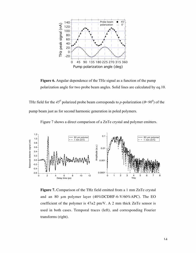
€
Lc =πc
ΩTHz nopt − λoptdnoptdλ
λopt
− nTHz
(11)
where nopt and nTHz are the optical and THz refractive indices of the material respectively,
ΩTHz is the THz angular frequency, λopt is the wavelength of the pump beam, and c is the
speed of light.
In OR the amplitude of the generated THz wave increases with the thickness of
the nonlinear medium. The linear EO effect is also directly proportional to the thickness
of the nonlinear medium. Therefore, in order to obtain larger THz power from an emitter
as well as high sensitivity and signal to noise ratio in THz EO detectors, it is important to
increase the thickness of both the emitter and detector as much as possible. However, if
the coherence length is small, the optical group velocity and the THz phase velocity will
only be matched for a limited range of THz frequencies. Therefore materials with shorter
coherence lengths will have narrower frequency responses.
The optical and THz refractive index of ZnTe, which is widely used in THz experiments,
is well known.33 The dispersion of the 40%DCDHF-6-V/60%APC composite is
presented in Fig.9 (left) by fitting of the Sellmeier dispersion formula
€
n2 = A +Bλ2
λ2 − λabs2 (12)
to our experimental data (solid circles). For λabs = 600 nm the best fit is obtained with
A=2.3951, B= 0.2072. The dispersion in our material is calculated to be −0.45 µm-1 at
800 nm. We measured the THz refractive index to be 1.9 in the range of 0.5-3.5 THz by
transmitting a THz pulse through a 130 µm thick layer of DCDHF-6-V/APC.

19
2.0
1.9
1.8
1.7
1.6
1.5
Refra
ctive
inde
x
1600140012001000800600Wavelength (nm)
theory experiment
4035302520151050El
ectro
-opt
ic c
oeffi
cien
t (pm
/V)
1600140012001000800600Wavelength (nm)
theory experiment
Fig.9. Left : Optical dispersion of 40%DCDHF-6-V/60%APC. Solid line is a fitof a Sellmeier dispersion formula (12) to the experimental data (solid circles) with
λabs = 600 nm, A=2.3951, B= 0.2072. Right : dispersion of the EO coefficient
calculated with eq.17 fitted to the experimental data with D = 3.1.
Comparing the coherence length of ZnTe to that of our polymers we note the
following (Figure 10 left ); at ∼2 THz in ZnTe the group velocity of the optical pulse is
matched with the THz phase velocity resulting in a sharp resonance. In the low
4
3
2
1
0
Cohe
renc
e le
ngth
(mm
)
3.53.02.52.01.51.00.50.0Frequency (THz)
ZnTe Polymer
140
120
100
80
60
40
20
0
Cohe
renc
e le
ngth
(µm
)
151413121110987Frequency (THz)
ZnTe Polymer
Figure 10. Left : Coherence length in ZnTe and a polymer composite of40% DCDHF-6-V/40% APC calculated by eq.11 with our experimental
index data. Right : The projected coherence length of the same materialsin the range of 7-15 THz.

20
frequency range, the crystal is definitely better than the polymer. But, as the THz
frequency increases, the coherence length in polymers should become larger than that of
the crystal (Figure 10, right). However, additional measurements are necessary to
experimentally support this prediction since our measurements on the polymer only
covered the 0.5-3.5 THz region.
Previously, Nahata et al.21 reported the coherence length for EO polymer to be 1.9
mm at 0.5 THz and 0.95 mm at 1 THz, which is about 20 times larger than that of
LiNbO3. A wideband response up to 33 THz has been experimentally demonstrated with
this kind of EO polymer sensor.23
The frequency response of an EO sensor has been studied in detail.18,34,35 The
detected THz signal is represented as a product of three frequency dependent terms34 : the
first term describes the frequency limitations of the light source, which depend on the
pulse duration of pump and probe beams, the second describes the EO dispersion of the
emitter and sensor, and the third one involves the group velocity mismatch (GVM)
between optical and THz pulse as discussed above. These 3 terms act as a filters
affecting the frequency response of the whole THz system.
The goal of this section is to compare nonlinear media only, therefore we will not
take into consideration the limitations of the laser source, so the response function can be
presented as35,
€
R(Ω) = rEO (Ω)G(Ω), (13)
where rEO(Ω) is the frequency dependent EO coefficient and G(Ω)18 is the GVM factor

21
€
G(Ω) =T(Ω)δ(Ω)
ei2πΩtdt =0
δ (Ω)
∫T(Ω) ei2πΩδ (Ω) −1( )
i2πΩδ(Ω)(14)
with the Fresnel transmission coefficient for THz waves T(Ω),
€
T(Ω) =2
1+ nTHz (Ω), (15)
and
€
δ(Ω) =Lcng (λ0) − nTHz (Ω)( ) (16)
is the GVM time,18 where ng(λ0) is the material group index at the probe wavelength λ0,
nTHz(Ω) is the THz refractive index, L is the EO sensor thickness, and c is the speed of
light.
By applying time dependent perturbation theory in the two-level model
approximation,36 the dispersion of the EO coefficient in poled polymers can be written as,
€
r33(λ) = D n2(λ) + 2n2(λ)
2 λ2 3λ2 − λabs2( )
λ2 − λabs2( )2
, (17)
where D is a constant, λabs is the wavelength of the absorption maximum, and λ is the
optical wavelength. Fig.9 (right) shows the fit of this equation to the experimental
measurements for our material. Being purely electronic, the nonlinearity of EO polymers
is expected to remain constant in the mid- and far-infrared frequency ranges.
In contrast to EO polymers, the nonlinearity in crystals is mostly ionic.18 The
frequency dependent rEO(Ω) is modeled for GaP and ZnTe as35
€
rEO (Ω) = re 1+C(hΩTO )
2
(hΩTO )2 − (hΩ)2 + ihΩγ
, (18)

22
where re, C, and γ are constants and ΩTO is the transverse-optical phonon frequency.
Crystals are characterized by phonons associated with lattice vibrations. For example,
there are phonon absorption bands in ZnTe at 5.3 THz, in InP at 9 THz, and in GaP at 11
THz.18,35
Fig.11 shows the comparison of the frequency response of 100 µm thick ZnTe,
GaP and EO polymer sensors calculated by eq.13. Both the EO dispersion (eq.17,18) and
the GVM (eq.14) affect the response. Due to resonances, many gaps can be seen in both
the ZnTe and GaP responses. These spectral distortions are observed experimentally.35,37
In contrast, since poled polymers are amorphous materials without phonon bands, their
EO coefficient is frequency independent in the mid- and far-infrared range and a flatter
frequency
10-4
10-3
10-2
10-1
100
Resp
onse
(arb
.uni
ts)
2520151050Frequency (THz)
100 µm GaP ZnTe polymer
Fig.11. Calculated frequency response of 100 µm thick ZnTe, GaP and EOpolymer sensors from eq.12 for 800 nm for both ZnTe and EO polymer, and 835
nm for GaP. C =-0.07 and –0.47, γ =3.01 cm-1, and 4.3 cm-1 for ZnTe and GaP
respectively35. The polymer and ZnTe were simulated at 800 nm and GaP at 835
nm. The group indices of the polymer, ZnTe, and GaP are 2.05, 3.24 and 3.56respectively. The THz refractive index was calculated from eq.4 in Ref. (33) for
ZnTe and from Ref. (38) for GaP.

23
response at least up to 20 THz is anticipated. An almost flat response over
20 THz has been observed experimentally in a poled polymer THz sensor.23
A large coherence length due to low dispersion and the absence of phonons
together with high EO coefficients make EO polymers attractive materials for THz
experiments.
Conclusion
We have reported an experimental study of THz generation and detection with
poled polymers. We have developed a technique to obtain poled polymer layers with
thicknesses in the range of 50-350 µm. These polymers are more efficient THz emitters
and detectors than the standard ZnTe crystal. Direct comparison shows that the THz field
emitted from an 80 µm thick poled polymer is equal to that emitted from a 1 mm thick
ZnTe crystal.
In comparison to crystals, EO polymers have two distinct advantages, higher EO
coefficients and larger coherence lengths at high frequencies. Both these factors are
important for THz applications, especially wideband applications, because the thickness
of emitters and detectors should be large to provide a high sensitivity and signal to noise
ratio without limiting the frequency response. Additionally, polymers are amorphous
materials and therefore they do not have phonon absorption bands.
EO polymers are versatile, permitting various chromophores and polymer
matrices to be employed to fit specific requirements such as peak absorption and material
refractive index. In addition, EO polymer composites are easy to prepare and cheap
compared to crystals.

24
However, EO polymers have some disadvantages. First, thermal vibrations tend
to randomize the poled order of chromophores decreasing the nonlinear properties of the
medium over time. However, our current EO polymers can be used for at least a couple
of weeks without significant degradation of EO properties if stored at room temperature.
Higher Tg EO polymers with larger EO coefficients are being developed.39 These
materials exhibit no appreciable degradation of their EO coefficient over thousands of
hours when stored at 850C. Another disadvantage of EO polymers is that the thickness of
a highly poled polymer layer is limited to a few hundred micrometers. This is because an
extremely high voltage needs to be applied to a thick layer in order to achieve a high
poling field. However, as discussed above the wide frequency response requires thin and
efficient emitters and sensors, so this limitation may not be significant for wideband
applications. Also, EO polymers, when illuminated near their absorption maximum, have
a low damage threshold compared to crystals. This does not allow high pump powers
and limits our SNR, currently.
We also developed a theoretical model of THz generation from a poled polymer
via optical rectification and verified this model experimentally in a system using a
polymer emitter and a ZnTe sensor. This model allows the adjustment of the orientation
of both the emitter and detector for the best THz performance for a given combination of
pump and probe beam polarizations.
In this study we did not yet demonstrate a wideband THz spectrum. In the future
we plan to perform the THz experiments with polymers in a dry environment with shorter
laser pulses to demonstrate a wideband spectral response. We also plan to study the THz
absorption in our materials.

25
Acknowledgments
The authors thank Robert Twieg and Meng He from the Kent State University for
providing the DCDHF chromophores and Warren Herman from the Laboratory of
Physical Sciences for measuring the optical refractive indices of our EO polymer films.
This work is supported by the National Science Foundation (ECS-0139457).
References
(1) Mittleman, D.; Jacobsen, R. H.; Nuss, M. IEEE J. Sel. Topics Quant.
Elect. 1996, 2, 679.
(2) Fitzgerald, A. J.; Berry, E.; Zinovev, N. N.; Walker, G. C.; Smith, M. A.;
Chamberlain, J. M. Phys. Med. Biol. 2002, 47, R67.
(3) Smye, S. W.; Chamberlain, J. M.; Fitzgerald, A. J.; Berry, E. Phys. Med.
Biol. 2001, 46, R101.
(4) Mittleman, D. M.; Gupta, M.; Neelamani, R.; Baraniuk, R. G.; Rudd, J.
V.; Koch, M. Appl. Phys. B 1999, 68, 1085.
(5) Hu, B. B.; Nuss, M. C. Opt. Lett. 1995, 20, 1716.
(6) Cheville, R. A.; Grischkowsky, D. Opt. Lett. 1995, 20, 1646.
(7) Cheville, R. A.; Grischkowsky, D. Appl. Phys. Lett. 1995, 67, 1960.
(8) Cheville, R. A.; McGowan, R. W.; Grischkowsky, D. IEEE Trans. Antenn.
Propag. 1997, 45, 1518.
(9) Krishnamurthy, S.; Reiten, M. T.; Harmon, S. A.; Cheville, R. A. Appl.
Phys. Lett. 2001, 79, 875.

26
(10) Nuss, M. C.; Orenstein, J. Terahertz time-domain spectroscopy. In
Millimeter and Sub-millimeter Wave Spectroscopy in Solids; Grüner, G., Ed.; Springer:
Berlin, 1998; Vol. 74; pp 7.
(11) Grischkowsky, D.; Keiding, S.; van Exter, M.; Fattinger, C. J. Opt. Soc.
Am. B 1990, 7, 2006.
(12) van Exter, M.; Fattinger, C.; Grischkowsky, D. Opt. Lett. 1989, 14, 1128.
(13) Duvillaret, L.; Garet, F.; Coutaz, J. L. IEEE J. Sel. Topics Quant. Elect.
1996, 2, 739.
(14) Han, P.; Zhang, X. C. Meas. Sc. Tech. 2001, 12, 1747.
(15) Chen, Q.; Tani, M.; Jiang, Z.; Zhang, X. C. JOSA B 2001, 18, 823.
(16) Planken, P. C. M.; Nienhuys, H.-K.; Bakker, H. J.; Wenckebach, T. JOSA
B 2001, 18, 313.
(17) Wu, Q.; Zhang, X.-C. IEEE J. Sel. Topics Quant. Elect. 1996, 2, 693.
(18) Wu, Q.; Zhang, X.-C. Appl. Phys. Lett. 1997, 70, 1784.
(19) Pan, F.; Knöpfle, G.; Bosshard, C.; Follonier, S.; Spreiter, R.; Wong, M.
S.; Günter, P. Appl. Phys. Lett. 1996, 69, 13.
(20) Carey, J. J.; Bailey, R. T.; Pugh, D.; Sherwood, J. N.; Cruickshank, F. R.;
Wynne, K. Appl. Phys. Lett. 2002, 81, 4335.
(21) Nahata, A.; Auston, D.; Wu, C.; Yardley, J. T. Appl. Phys. Lett. 1995, 67,
1358.
(22) Nahata, A. Opt. Lett. 2001, 26, 385.
(23) Cao, H.; Heinz, T. F.; Nahata, A. Opt. Lett. 2002, 27, 775.
(24) Sinyukov, A. M.; Hayden, L. M. Opt. Lett. 2002, 27, 55.

27
(25) Hayden, L. M.; Sinyukov, A. M.; Leahy, M., R; French, J.; Lindahl, P.;
Herman, W. N.; Twieg, R. J.; Meng, H. J. Poly. Sci. B 2003, 41, 2492.
(26) Bosshard, C. S., K; Pretre, Ph; Hulliger, J; Florsheimer, M; Kaatz, P;
Gunter, P Organic Nonlinear Optical Materials; Gordon and Breach Science Publishers
SA: Basel, 1995; Vol. 1.
(27) Boyd, R. W. Nonlinear Optics; Academic Press: San Diego, 1992.
(28) Zhang, X.-C.; Jin, Y.; Ma, X. F. Appl. Phys. Lett. 1992, 61, 2764.
(29) Yariv, A. Optical electronics, 4th ed. ed.; Saunders College Pub:
Philadelphia, 1991.
(30) Sinyukov, A. M.; Hayden, L. M. (unpublished).
(31) Carrig, T. J.; Rodriguez, G.; Clement, T. S.; Taylor, A. J.; Stewart, K. R.
Appl. Phys. Lett. 1995, 66, 121.
(32) Han, P. Y.; Tani, M.; Pan, F.; Zhang, X.-C. Opt. Lett. 2000, 25, 675.
(33) Nahata, A.; Weling, A.; Heinz, T. F. Appl. Phys. Lett. 1996, 69, 2321.
(34) Gallot, G.; Grischkowsky, D. J. Opt. Soc. Am. B 1999, 16, 1204.
(35) Leitenstorfer, A.; Hunschek, S.; Shah, J.; Nuss, M. C.; Knox, W. H. Appl.
Phys. Lett. 1999, 74, 1516.
(36) Wortmann, R.; Poga, C.; Twieg, R. J.; Geletneky, C.; Moylan, C. R.;
Lundquist, P. M.; DeVoe, R. G.; Cotts, P. M.; Horn, H.; Rice, J. E.; Burland, D. M. J.
Chem. Phys. 1996, 105, 10637.
(37) Han, P. Y.; Zhang, X.-C. Appl. Phys. Lett. 1998, 73, 3049.
(38) Palik, E. D. Handbook of Optical Constants of Solids; Academic Press:
Boston, 1991.

28
(39) Ma, H.; Liu, S.; Luo, J.; Suresh, S.; Liu, L.; Kang, S. H.; Haller, M.;
Sassa, T.; Dalton, L. R.; Jen, A. K. Y. Adv. Func. Mater. 2002, 12, 565.


![Phase-matched scalable THz generation in two-color ... THz 10 THz 100 THz 1 PHz 10 PHz 300 m 30 m ... Kim presentation at Argonne 2012_no backup.ppt [Compatibility Mode] Author:](https://static.fdocuments.in/doc/165x107/5ac2b9eb7f8b9aca388e95a7/phase-matched-scalable-thz-generation-in-two-color-thz-10-thz-100-thz-1-phz.jpg)