Efficient Configuration of Storage Rack System as Per ...
18
Computational Engineering and Physical Modeling 1-2 (2018) 41-58 How to cite this article: Thombare CN, Sangle KK, Mohitkar VM, Kharmale SB. Efficient Configuration of Storage Rack System as Per Nonlinear Static Pushover Analysis under Triangular and Uniform Pattern of Lateral Loading Pattern. Comput Eng Phys Model 2018;1(2):41–58. https://doi.org/10.22115/cepm.2018.125616.1017 2588-6959/ © 2018 The Authors. Published by Pouyan Press. This is an open access article under the CC BY license (http://creativecommons.org/licenses/by/4.0/). Contents lists available at CEPM Computational Engineering and Physical Modeling Journal homepage: www.jcepm.com Efficient Configuration of Storage Rack System as Per Nonlinear Static Pushover Analysis under Triangular and Uniform Pattern of Lateral Loading Pattern C.N. Thombare 1* , K.K. Sangle 2 , V.M. Mohitkar 3 , S.B. Kharmale 4 1. Applied Mechanics Department, Cusrow Wadia Institute of Technology Pune, Maharashtra, India 2. Professor, Structural Engineering Department, Veermata Jijabai Technological Institute, Matunga, Mumbai, India 3. Director, Maharashtra State Board of Technical Education, Bandra (East) Mumbai, India 4. Assistant Professor, Applied Mechanics, Government College of Engineering and Research, Avasari (Kd), Pune, Maharashtra, India Corresponding author: [email protected] https://doi.org/10.22115/CEPM.2018.125616.1017 ARTICLE INFO ABSTRACT Article history: Received: 22 March 2018 Revised: 03 July 2018 Accepted: 11 July 2018 The individual components of cold-formed storage rack system are most vulnerable to local and torsional buckling lateral loads in addition to under gravity. Deterministic allotment of strength and ductility in the structural components and performance evaluation of appropriate techniques is considered in the capacity based design of cold-formed pallet rack system. Nonlinear time history analysis (NTHA) and nonlinear static pushover analysis (NSPA) are most commonly followed techniques for seismic performance evaluation of any structural systems. Although, NTHA is the most correct technique of seismic demand forecasting and performance evaluation, it is computationally heavy and even requires the selection and application of relevant set of ground excitations. A simple method for the nonlinear static analysis of complicated structures subjected to gradually increasing lateral loads (pushover analysis) is presented here. This paper presents investigation of efficient configuration of conventional pallet racking system on the basis of seismic performance by using NSPA. Finite element models of two different configurations of conventional pallet racking system are prepared and analyzed on the general purpose FE platform using ABAQUS 6.12 under monotonic unidirectional lateral loads. Results show that conventional pallet racking system with horizontal and inclined bracing is more efficient as evidenced from a fair judgment of the overall displacement, base shear and yielding demands. Keywords: Pallet racks; Cold-formed steel; Nonlinear pushover analysis; Base shear.
Transcript of Efficient Configuration of Storage Rack System as Per ...

Computational Engineering and Physical Modeling 1-2 (2018) 41-58
How to cite this article: Thombare CN, Sangle KK, Mohitkar VM, Kharmale SB. Efficient Configuration of Storage Rack System
as Per Nonlinear Static Pushover Analysis under Triangular and Uniform Pattern of Lateral Loading Pattern. Comput Eng Phys
Model 2018;1(2):41–58. https://doi.org/10.22115/cepm.2018.125616.1017
2588-6959/ © 2018 The Authors. Published by Pouyan Press.
This is an open access article under the CC BY license (http://creativecommons.org/licenses/by/4.0/).
Contents lists available at CEPM
Computational Engineering and Physical Modeling
Journal homepage: www.jcepm.com
Efficient Configuration of Storage Rack System as Per Nonlinear
Static Pushover Analysis under Triangular and Uniform Pattern
of Lateral Loading Pattern
C.N. Thombare1*, K.K. Sangle2, V.M. Mohitkar3, S.B. Kharmale4
1. Applied Mechanics Department, Cusrow Wadia Institute of Technology Pune, Maharashtra, India
2. Professor, Structural Engineering Department, Veermata Jijabai Technological Institute, Matunga, Mumbai, India
3. Director, Maharashtra State Board of Technical Education, Bandra (East) Mumbai, India
4. Assistant Professor, Applied Mechanics, Government College of Engineering and Research, Avasari (Kd), Pune,
Maharashtra, India
Corresponding author: [email protected]
https://doi.org/10.22115/CEPM.2018.125616.1017
ARTICLE INFO
ABSTRACT
Article history:
Received: 22 March 2018
Revised: 03 July 2018
Accepted: 11 July 2018
The individual components of cold-formed storage rack system are
most vulnerable to local and torsional buckling lateral loads in
addition to under gravity. Deterministic allotment of strength and
ductility in the structural components and performance evaluation
of appropriate techniques is considered in the capacity based
design of cold-formed pallet rack system. Nonlinear time history
analysis (NTHA) and nonlinear static pushover analysis (NSPA)
are most commonly followed techniques for seismic performance
evaluation of any structural systems. Although, NTHA is the most
correct technique of seismic demand forecasting and performance
evaluation, it is computationally heavy and even requires the
selection and application of relevant set of ground excitations. A
simple method for the nonlinear static analysis of complicated
structures subjected to gradually increasing lateral loads (pushover
analysis) is presented here. This paper presents investigation of
efficient configuration of conventional pallet racking system on the
basis of seismic performance by using NSPA. Finite element
models of two different configurations of conventional pallet
racking system are prepared and analyzed on the general purpose
FE platform using ABAQUS 6.12 under monotonic unidirectional
lateral loads. Results show that conventional pallet racking system
with horizontal and inclined bracing is more efficient as evidenced
from a fair judgment of the overall displacement, base shear and
yielding demands.
Keywords:
Pallet racks;
Cold-formed steel;
Nonlinear pushover analysis;
Base shear.

42 C. N. Thombare et al./ Computational Engineering and Physical Modeling 1-2 (2018) 41-58
1. Introduction
The cold-formed steel members are predominantly used for drive in and drive through steel
pallet rack structures. In usual storage rack structures, the box cross sections are used for beams,
while open thin walled perforated sections are used for columns, which connects beams and
columns together without bolting or welding. Therefore the design of storage rack structures is
quite complicated. The behaviour of the perforated columns is influenced by various buckling
modes e.g. local, distortional and global as well as by their common correlations. Usually the
response of beam to column is nonlinear. Besides, bracings are usually placed in the cross-aisle
direction. The requirement for organizing pallet racks in such a way that the material is
effectively stored and sufficiently available, affects the presence of bracings in the down-aisle
direction. The lateral stability is exclusively provided by the degree of continuity related with
beam to column connections in addition to base plate connections. Presently, for the design of
these frames, no particular code of practice available. The specifications given by Rack
Manufacturer’s Institute [1] followed by United States and other countries as a guidelines. For
seismic demand prediction and performance evaluation of structures nonlinear time history
analysis (NTHA) is the most correct method available. The selection and employment of relevant
set of ground excitations is the basic requirement of this method and needs a sophisticated
mathematical gadget which handles the analysis and gives results within the time. For
professional practice designers, a simpler analysis tool with less computational effort is required.
The nonlinear static pushover analysis (NSPA) method is a popular method and good alternative
method to time history analysis. To examine the performance of conventional pallet storage rack
systems using numerical analysis is the primary objective of the study demonstrated in this
paper. The analytical tests include nonlinear static pushover analyses of various configurations of
storage rack frames. The past research on static pushover analysis and on conventional pallet
rack systems is briefed in following section. Section 3 deals with details storage rack frame and
its configurations. Finite element modeling with validation and NSPA of rack frames are
presented in subsequent sections. Final section summarized the important findings from the
numerical tests on cold formed storage rack systems.
2. Review of past research
2.1. On push over analysis
To evaluate the structural attainment by calculating the strength and deformation capacities using
static nonlinear analysis and comparing these capacities with the demands at the equivalent
performance levels is the primary objective of the pushover analysis. The primary process of this
method is to execute a series of static analysis under gradually increasing lateral loads in its
principle directions to simulate the loading of the structure during the failure. The potential of the
pushover analysis has been conceived in the last 20 years and it is covered in the seismic
guidelines ATC-40 [2]. The pushover analysis is expected to provide information on many
responsive features that cannot be found from an elastic or dynamic analysis.
The following primary response characteristics are aimed from NSPA:

C. N. Thombare et al./ Computational Engineering and Physical Modeling 1-2 (2018) 41-58 43
i. Estimation of strength and deformation capacities structural system for fundamental mode
of vibration.
ii. Location of the crucial areas, where the inelastic strains are likely to be more.
iii. Consequences of strength deterioration of particular elements of the total structural
stability.
iv. Order of members yielding and collapse and the progression of the total capacity curve of
the structure.
The history of pushover analysis was highlighted by Krawinkler and Seneviratna [3]. Initially the
study was focused on discussions of the scope of suitability of the technique and its merits and
demerits, compared to static or nonlinear dynamic methods. Asawasongkram et al. [4] studied
the seismic performance assessment of the semi-rigid steel pallet rack structures located in
Thailand. A mathematical model of the structure was prepared by incorporating nonlinear
behaviour of semi-rigid beam to column joint. Chopra and Goel [5] attempted to extend
pushover analysis for taking into account higher failure modes. Kalkan and Chopra [6] was
presented a modal pushover based scaling (MPS) procedure to scale ground motions for the use
in a nonlinear response history analysis of buildings. Fajfar [7] was presented a simple nonlinear
(N2-method) for the seismic analysis of structures. This method composes the pushover analysis
results of a multi degree of freedom (MDOF) model with the response spectrum analysis of an
equivalent single degree of freedom (SDOF) system in typical acceleration-displacement format.
Thus, this method enables the visualization of the seismic response of the system and establishes
the relation between the fundamental quantities regulating seismic response. Among the different
techniques of pushover analysis, NSPA is more favored as it is simple, computationally light and
still provides more accurate results for fundamental mode of vibration. In the current study NSPA
on two different configurations of conventional pallet racking system is conducted to examine
the strength and deformation capacities of storage rack systems. The pattern of lateral load
adopted for NSPA conforms to the equivalent static force distribution pattern of UBC-
1997specifications.
2.2. On conventional pallet racking systems
A three dimensional (3D) FE model of storage rack systems prepared by Sangle et al. [8] using
ANSYS [9] software and free vibration modal analysis carried out in a conventional semi-rigid
storage rack structure with 18 types of column sections developed. The finite element buckling
and dynamic analyses of two dimensional (2D) single frames and 3D frames of cold-formed steel
sections with semi-rigid connections used in the conventional pallet racking system also
performed. The results obtained from buckling analysis of the single 2D frames, experimental
study and effective length approach given by RMI were compared. The buckling analysis results
were obtained for FE model used for the single 2D frames further extended to 3D frames with
semi-rigid connections. However, Sangle et al. does not consider material as well as geometric
nonlinearity in their research. Bajoria et al. [10] prepared finite element 3D models using
ANSYS and modal analysis are carried on pallet rack structures. A parametric study is carried
out for finding fundamental mode shapes and time period. Sangle et al. [11] studied elastic
buckling analysis of 2D and 3D pallet rack frames with semi-rigid connections. Experimental

44 C. N. Thombare et al./ Computational Engineering and Physical Modeling 1-2 (2018) 41-58
results, effective length approach of RMI and FEM analysis of single 2D frames were compared.
The main object is to determine the linear buckling load of single 2D frames and to determine
the stability of 3D frames of typical cold-formed steel storage rack structures, with semi-rigid
connection. Use of stiffeners in the column section enhances the buckling load capacity
considerably. Thombare et al. [12] considered the material as well as geometric nonlinearity in
their research further to extend their study. The procedure to perform the multi mode pushover
(MMP) method was studied by Sasaki and Paret [13] and this method was applied to various
structures. MMP uses the capacity spectrum method to correlate graphically the pushover plot to
the earthquake demand. Kalavagunta et al. [14] investigated the progressive collapse of cold-
formed steel pallet rack structures subjected to earthquake loading using pushover analysis.
Moghadam and Tso [15] continued the pushover method for seismic damage estimation of
unsymmetrical structures. It is shown that the exactness of the proposed 3D pushover analysis is
identical to those applied to planar frames with the help of an illustration. This method is found
to be more advantageous in calculating the overall response parameters such as inter storey drifts
than local damage indicators such as beams or column ductility demands.
3. Details of storage rack frames
The column cross sections used in the study are Medium Weight (MW) sections having three
thicknesses 1.6 mm, 1.8 mm, and 2.0 mm each and Heavy Weight (HW) sections having three
thicknesses 2.0 mm, 2.25mm and 2.5mm each. Their cross sectional details of medium weight
and heavy weight columns are shown in Fig. 1 and in Fig. 2 respectively. Three different
thicknesses are selected to know the variation in behaviour when the sections are made locally
strong by having a higher thickness. Fig. 3 to Fig. 5 presents the particulars of the finite element
models. Spacer bars are also used to avoid local buckling of the column sections in the present
study.
For the cross sections shown in Fig. 1 and in Fig. 2, cross sectional properties are estimated
based on the weighted average section. A weighted average section is a section that uses an
average thickness in the portion of web to account for the absence of the material due to the
perforations along the length of the section. Table 1 shows the cross sectional properties of the
column sections and Table 2 presents of material properties of the same column sections.

C. N. Thombare et al./ Computational Engineering and Physical Modeling 1-2 (2018) 41-58 45
Fig. 1. Medium weight column section 1.6mm, 1.8mm and 2.0 mm thick[12].
Fig. 2. Heavy weight column section 2.0mm, 2.25mm and 2.5mm thick [12].
Fig. 3. Heavy /Medium Weight column section in ABAQUS [12].

46 C. N. Thombare et al./ Computational Engineering and Physical Modeling 1-2 (2018) 41-58
Fig. 4. Typical B1 type frame with inclined bracing only [12].
Fig. 5. Typical B2 type frame with inclined and horizontal bracing only [12].
Fig. 4 and Fig. 5 shows two distinct categories of storage rack frames. Fig. 4 shows B1 type
frame which consists of inclined braces only and Fig. 5 shows B2 type frames which consist of
inclined as well as horizontal bracing. Columns are typical HAT sections with and without spacer
bars. For the purpose of easy connection between the beam and end connector the column
sections in pallet racks are perforated. The local buckling load of the member is reduced due to
the presence of perforations and increases the global buckling load of the system. The perforated
flat plate loaded with uniform compressive load decreases the elastic local buckling load;
however, due to perforations in the flat plate, there causes a change in the wavelength of the
buckling mode which actually increases the buckling load away from the perforations [16]. The
geometry, material properties and the boundary conditions will affect this increase in load

C. N. Thombare et al./ Computational Engineering and Physical Modeling 1-2 (2018) 41-58 47
carrying capacity of the member. Use of non perforated section properties is allowed in the
current specifications to predict the elastic buckling strength of perforated members, by
assuming that the reduction in the overall elastic buckling strength does not have a significant
effect due to the presence of such perforations in the members.
Table 1 Sectional Properties of columns (uprights) in pallet storage rack frames.
Type of section A (mm2) Ixx (mm4) Iyy (mm4) J (mm4) CG (x, y)
(mm) Warping Coefficient (mm6)
MW-1.6 389.53 269028 302208 311.6 0, 46.31 7.68×10⁸
MW-1.8 438.21 302626 339983 443.58 0, 46.32 8.64×10⁸
MW-2.0 487.00 336369 377784 608.774 0, 46.31 9.61×10⁸
HW-2.0 593.02 514270 854484 744.669 0, 54.66 1.89×10⁹
HW-2.25 667.06 578437 961214 1060.02 0, 54.66 2.13×10⁹
HW-2.5 741.21 642731 1068050 1454.09 0, 54.67 2.36×10⁹
Table 2 Properties of cold formed steel (CFS) [12].
Yield stress
(MPa)
Ultimate stress
(MPa)
Modulus of elasticity, E
(MPa)
Density
(kg/m3)
Poisson’s ratio,
365 569 212×103 7860 0.29
Each of the B1 and B2 frame are subdivided into following category.
1. B1 Heavy Weight frames without Spacer bars in upright/column
2. B1 Heavy Weight frames with Spacer bars in upright/column
3. B1 Medium Weight frames without Spacer bars in upright/column
4. B1 Medium Weight frames with Spacer bars in upright/column
5. B2 Heavy Weight frames without Spacer bars in upright/column
6. B2 Heavy Weight frames with Spacer bars in upright/column
7. B2 Medium Weight frames without Spacer bars in upright/column
8. B2 Medium Weight frames with Spacer bars in upright/column
The typical designation of storage rack frame used in this study is as follows:
Spacing of Spacer Bar
100 or 200 mm Type of Column Section Either
Medium Weight (MW) or Heavy
Weight (HW) Thickness of Column
Upright Section 1.6, 1.8,
2.0 mm for MW & 2.0,
2.25, 2.5 mm for HW
Type of Bracing B1 or B2
MW1.6B1-100

48 C. N. Thombare et al./ Computational Engineering and Physical Modeling 1-2 (2018) 41-58
4. Finite element modeling and validation
For numerical analysis ABAQUS [17], general purpose FE software is used. In FE Model of
storage rack tie constraint is used to connect translational degrees of freedom (U1, U2 and U3) of
a shell element to those of solid element. S4R shell element and C3D8R brick elements are used
to model columns and bracings respectively for all finite element models presented in this study.
To find local buckling of individual components like flange, web and lip of the cross sections,
shell (S4R) and brick (C3D8R) elements are used to model components of a storage rack
structures. Table 3 presents the details of these elements.
Table 3
Details of the elements used for finite element analysis [12]. Part of frame Element Description
Column upright
section S4R
4-noded, quadrilateral, stress/displacement shell element with
reduced integration and a large-strain formulation
Horizontal bracing C3D8R 8-noded general purpose linear brick element, with reduced
integration (1 integration point) and hourglass control.
Inclined bracing C3D8R 8-noded general purpose linear brick element, with reduced
integration (1 integration point) and hourglass control.
Spacer Bar C3D8R 8-noded general purpose linear brick element, with reduced
integration (1 integration point) and hourglass control.
Table 4
Validation of FE model with experimental study by Sangle et al. [8].
Column frame Pe in kN
(Experimental)
Pe in kN
(Analytical) % Difference
MW-1.6-B1 103.51 116.02 -12.09
MW-1.6-B2 115.45 129.52 -12.19
MW-1.8-B1 166.78 132.68 20.45
MW-1.8-B2 176.88 147.14 16.81
MW-2.0-B1 200.41 149.7 25.30
MW-2.0-B2 215.46 164.86 23.48
HW-2.0-B1 223.45 236.2 -5.71
HW-2.0-B2 235.26 269 -14.34
HW-2.25-B1 264.24 268.65 -1.67
HW-2.25-B2 275.56 304.4 -10.47
HW-2.5-B1 295.46 301.63 -2.09
HW-2.5-B2 305.56 340.12 -11.31
Table 5
Results of the convergence study [12]. Mesh size of the frame HW-2.0-
B1 (height 3.1m) 50mm 40 mm 30mm 20 mm 10mm 5mm
Linear Buckling Load in (kN) 256.11 242.97 240.70 239.21 236.2 236.09
C. N. Thombare et al./ Computational Engineering and Physical Modeling 1-2 (2018) 41-58 49
Sangle et al studied the three dimensional FE planer model and validated it with experimental
results of stability analysis. Analytical results of finite element models are shown in Table 4 and
compared with experimental results, they are in good agreement with each other. Thus the model
is validated. For a frame HW2.0B1 of height 3.1m convergence study is carried out for obtaining
the appropriate mesh size of the various parts of the frame such as column sections, bracings and
spacer bar, etc. Table 5 highlights the results of convergence study. For convergence study
automatic mesh (size 10 mm x 10 mm) was found to be appropriate and same is adopted for
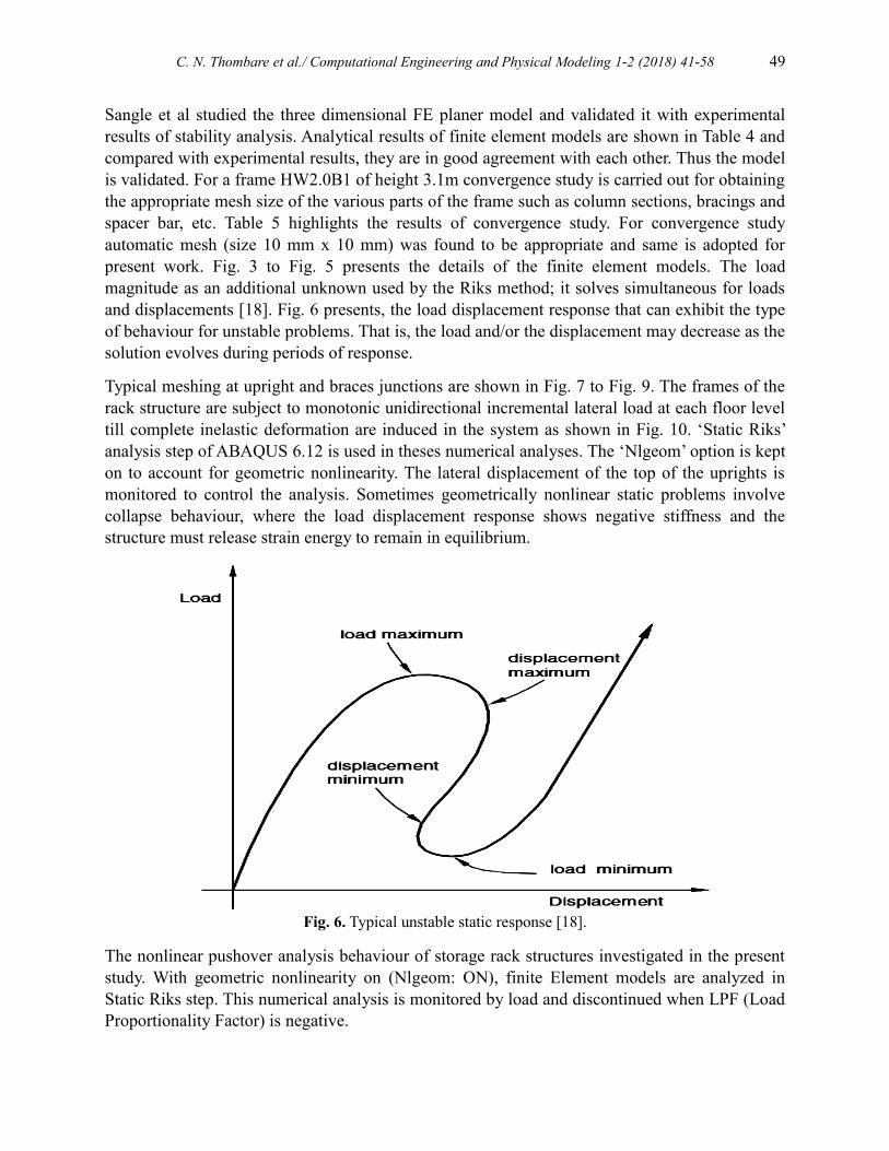
present work. Fig. 3 to Fig. 5 presents the details of the finite element models. The load
magnitude as an additional unknown used by the Riks method; it solves simultaneous for loads
and displacements [18]. Fig. 6 presents, the load displacement response that can exhibit the type
of behaviour for unstable problems. That is, the load and/or the displacement may decrease as the
solution evolves during periods of response.
Typical meshing at upright and braces junctions are shown in Fig. 7 to Fig. 9. The frames of the
rack structure are subject to monotonic unidirectional incremental lateral load at each floor level
till complete inelastic deformation are induced in the system as shown in Fig. 10. ‘Static Riks’
analysis step of ABAQUS 6.12 is used in theses numerical analyses. The ‘Nlgeom’ option is kept
on to account for geometric nonlinearity. The lateral displacement of the top of the uprights is
monitored to control the analysis. Sometimes geometrically nonlinear static problems involve
collapse behaviour, where the load displacement response shows negative stiffness and the
structure must release strain energy to remain in equilibrium.
Fig. 6. Typical unstable static response [18].
The nonlinear pushover analysis behaviour of storage rack structures investigated in the present
study. With geometric nonlinearity on (Nlgeom: ON), finite Element models are analyzed in
Static Riks step. This numerical analysis is monitored by load and discontinued when LPF (Load
Proportionality Factor) is negative.

50 C. N. Thombare et al./ Computational Engineering and Physical Modeling 1-2 (2018) 41-58
Fig. 7. Details of joint of frame and meshing of column section without spacer bar [12].
Fig. 8. Details of joint of frame and meshing of column section with spacer bar @ 100 mm c/c [12].
Spacer bar @ 100 mm c/c

C. N. Thombare et al./ Computational Engineering and Physical Modeling 1-2 (2018) 41-58 51
Fig. 9. Details of joint of frame and meshing of column section with spacer bar @ 200 mm c/c
[12].
Figure 10: Boundary condition and loading for storage rack frames
For finite element analysis following assumptions are made:
i. The connection between the braces and columns (uprights) are considered to be rigid.
ii. All three rotations and displacements are allowed at the loading end of the upright and at
the bottom base are assumed as fixed.
The structural details of the rack structures used in this study are as follows:
Upright sections = i) Medium Weight Hat Section of 1.6mm, 1.8mm and 2.0mm thick.
Spacer bar @ 200 mm c/c

52 C. N. Thombare et al./ Computational Engineering and Physical Modeling 1-2 (2018) 41-58
ii) Heavy Weight Hat Section of 2.0 mm, 2.25 mm and 2.5 mm thick
Width of bay= 1 m.
Depth of rack shelve =0.75m.
Height of the frame =3.1m.
Centre to centre distance between beam= 0.9m
Following categories summarizes the criterions that have an impact on the value of base shear
and displacement at collapse of complete pallet rack structure in the down-aisle direction.
i. First criterion is a type of column upright section, to account for this; here 6 types of
upright sections as shown in Fig. 2 are selected.
ii. Second criterion is of column (upright) frame configuration, two type of upright frame
configuration in a cross aisle direction is considered (i.e. horizontal with inclined bracing
and only inclined bracing).
iii. Third criterion is spacing of spacer bars for column (uprights) frame configuration, three
types of arrangements are considered:
a) without spacer bar,
b) with spacer bar @ 100mm spacing and
c) with spacer bar @ 200mm spacing
5. Analysis and results
Nonlinear static pushover analysis (NSPA) is performed for various configurations of storage
rack frames subjected to two distinct lateral load distribution patterns to estimate the capacities
both in the form of base shear and inelastic deformation. These distribution patterns are: UBC -
1997 “Inverted Triangular Distribution”, and “Uniform Distribution”
5.1. UBC-1997 Loading
Lateral load distribution (Inverted Triangular) pattern is applied transversely to the structures
across the height of the structure based on the following Eq. (1) mentioned in FEMA-356 [19]
and in Uniform Building Code (UBC- 1997) [20]:
1
k
x xx n
k
i i
i
W hF V
W h
(1)
where, ‘Fx’ = the applied lateral force at level ‘x’,
‘W’ = the story weight,
‘h’= the story height and
‘V’= the design base shear, and
‘n’= the number of stories.
The summation in the denominator is carried through all story levels. This results in an inverted
triangular distribution when ‘k’ is set equal to unity.

C. N. Thombare et al./ Computational Engineering and Physical Modeling 1-2 (2018) 41-58 53
Table 6
Variation of ultimate base shear of B1 and B2 type frames with respect to section thickness and use of
spacer bars (as per UBC-1997 and FEMA-356 Inverted Triangular Loading).
Type of
frame
Thickness
of elements
(mm)
Ultimate Base Shear (N)
B1 B1-200 B1-100 B2 B2-200 B2-100
MW:
Medium
Weight
1.6 27490 28308 28508 43362 43792 44751
1.8 29146 30093 30261 44053 45764 46279
2.0 30622 31950 32155 44272 47652 48269
HW:
Heavy
Weight
2.0 33704 34399 34565 44651 49334 49598
2.25 35690 36659 37052 44944 50743 50898
2.5 39841 40469 41398 45332 54795 55674
Table 6 shows ultimate base shear obtained from non linear static pushover analyses on B1 and
B2 type frames with inverted triangular loading. Fig. 11 and Fig. 12 represent some of typical
pushover plots for two distinct configurations of storage rack frames. The objective of pushover
plot is to obtain the maximum capacity of the system in terms of lateral load resistance under the
action of the monotonic unidirectional lateral load representing the fundamental mode of
vibration. As observed from these graphs B1 type of frames (with inclined bracing only) offers
almost 45% less lateral load resistance in comparison with B2 type of frame (with inclined and
horizontal bracing only). Moreover the use of spacer bar in uprights delays the torsional buckling
and enhances the lateral load resistance. For very thin sections, under inverted triangular loading,
the pushover analysis is aborted in between because of local instability. The system over the
strength of B2 type of frame is significantly more than that of B1 type of frame. Moreover the
use of spacer bar in uprights delays the torsional buckling and enhances the lateral load
resistance. These plots also highlight that frame with section thickness less than 2.25 mm the
local buckling in braces and columns restricts the ultimate lateral load resistance capacity. For
very thin sections the pushover analysis is aborted in between because of local instability.
Fig. 11. Base shear verses upright top displacement for B1 (UBC-1997) Loading.
0
5000
10000
15000
20000
25000
30000
35000
40000
45000
0 50 100 150 200 250
Ba
se S
hea
r N
Upright Top Displacement
B1-Inverted Triangular Loading (UBC-1997)
B1-1.6mm-MW
B1-1.8mm-MW
B1-2mm-MW
B1-2mm-HW
B1-2.25mm-HW
B1-2.5mm-HW

54 C. N. Thombare et al./ Computational Engineering and Physical Modeling 1-2 (2018) 41-58
Fig. 12. Base shear verses upright top displacement for B2-200 (UBC-1997) Loading.
Fig. 13. B1-200-1.6 mm MW frame von Mises stress contours at an instant of maximum top
displacement.
0
10000
20000
30000
40000
50000
60000
0 100 200 300 400 500
Ba
se S
hea
r in
N
Upright Top Displacement
B2-200- Inverted Triangular Loading (UBC-1997)
B2-200-1.6mm-MW
B2-200-2mm-MW
B2-200-2mm-HW
B2-200-2.25mm-HW
B2-200-2.5mm-HW
B2-200-1.8mm-MW

C. N. Thombare et al./ Computational Engineering and Physical Modeling 1-2 (2018) 41-58 55
Fig. 14. B2-1.6 mm MW frame von Mises stress contours at an instant of maximum top displacement.
The von Mises stress contours for 1.6 mm thick B1 and B2 types of storage rack systems are
shown in Fig. 13 and Fig. 14. These stress contours are captured in an instant of maximum lateral
drift as obtained from pushover analyses. Theses stress contours provide valuable information
regarding spread of inelastic deformations as well as identify the critical locations where local
instability restricted the maximum lateral load carrying capacity of the system. For B1 type
frames with very thin section (= 1.6 mm) the local buckling of inclined braces and for B2 type
frame flexural torsional buckling of upright without spacer bars restricts the optimum lateral
strength of the system.
5.2. Uniform distribution
The uniform distribution pattern is ideally suited for low rise and low inertia structural system
and hence adopted for the storage rack frames [21]. A constant load distribution consists of
lateral forces at each floor level proportional to the floor mass is adopted. Table 7 shows ultimate
base shear obtained from non linear static pushover analyses on B1 and B2 type frames subjected
to uniform loading. Fig. 15 represents some of the typical pushover plot for B2-200
configuration of storage rack frames subjected to uniform loading.
Table 7
Variation of ultimate base shear of B1 and B2 type frames with respect to section thickness and use of
spacer bars (as per UBC Loading).
Type of
frame
Thickness
of elements
(mm)
Ultimate Base Shear (N)
B1 B1-200 B1-100 B2 B2-200 B2-100
MW:
Medium
Weight
1.6 38367.82 39555.93 41342.56 56081.52 60150.16 61137.90
1.8 39406.64 42170.41 43536.25 58101.28 61067.68 61807.20
2.0 41846.99 44812.41 45872.28 58893.64 62191.80 63088.86
HW:
Heavy
Weight
2.0 44661.43 47396.84 48103.07 62401.36 62710.90 65834.14
2.25 46662.28 49063.76 51107.06 63518.81 65545.55 68616.12
2.5 50096.45 53857.46 55932.79 66339.65 71339.65 76218.83

56 C. N. Thombare et al./ Computational Engineering and Physical Modeling 1-2 (2018) 41-58
Fig. 15. Base shear versus upright top displacement for B2-200 (UBC-1997) Loading.
6. Conclusions
To calculate the base shear at the time of collapse and maximum drift, to study the formation of
plastic hinges, to study the collapse mechanism and to improve the base shear at the time of
collapse of cold-formed steel pallet rack structure are the objectives of this study. The cold-
formed steel pallet rack structures are analyzed using NSPA method under different parameters
like the thickness of members and the type of the frame structure. NSPA is a more efficient tool
for analysis for the pallet rack structures that gives fair judgment of the base shear, displacement
and development of plastic hinges at each incremental load.
Following significant observations and findings are highlighted below:
As observed from base shear verses lateral displacement graph initial elastic stiffness is
more for B2 type frame (inclined bracing with horizontal bracing) than B1 type frame
(inclined bracing).
B2 frame shows the gradual yielding up to 7% drift whereas B1 type frame shows the
gradual yielding up to 5% drift.
Failure due to buckling of braces (local failure) having a thickness less than 2.5 mm is
observed in both types of frames.
Considering the gradual yielding (i.e. sufficient inelastic deformation capacity) and lateral
load resistance, B2 type frame is more efficient than B1 type frame.
Use of spacer bars in uprights proves to be efficient to avoid flexural torsional buckling of
columns.
B1 type frame without spacer bars with inverted triangular loading (UBC-1997) offers
almost 45% less lateral load resistance than uniform loading.
0
10000
20000
30000
40000
50000
60000
70000
80000
0 100 200 300 400
Ba
se S
hea
r in
N
Upright Top Displacement
B2-200-Uniform Loading
B2-200-1.6mm-MW
B2-200-1.8mm-MW
B2-200-2mm-MW
B2-200-2mm-HW
B2-200-2.25mm-HW
B2-200-2.5mm-HW

C. N. Thombare et al./ Computational Engineering and Physical Modeling 1-2 (2018) 41-58 57
Among two distinct lateral distributions adopted for NSPA, for all configurations of
storage rack systems “uniform distribution patterns” provide upper bound estimate of base
shear and drift.
Acknowledgement
The authors appreciate their thanks to friends and colleagues from the V.J.T.I. Mumbai,
University of Mumbai, and C. W. I. T. Pune for their support in the aforesaid research.
References
[1] Institute RM. Specification for the design, testing, and utilization of industrial steel storage
racks. Rack Manufacturers Institute; 2000.
[2] ATC-40. Seismic evaluation and retrofit of concrete buildings, Report ATC-40, Applied
Technology Council, Redwood City, U.S.A. (1996) (also Report SSC 96-01, Seismic Safety
Commission, State of California, Sacramento, U.S.A.) n.d.
[3] Krawinkler H, Seneviratna GDPK. Pros and cons of a pushover analysis of seismic
performance evaluation. Eng Struct 1998;20:452–64. doi:10.1016/S0141-0296(97)00092-8.
[4] Asawasongkram N, Chomchuen P, Premthamkorn P. Seismic performance evaluation of steel
storage racks using experimental results of beam-to-column connection. 2nd Eur. Conf. Earthq.
Eng. Seismol., 2014, p. 25–9.
[5] Chopra AK, Goel RK. A modal pushover analysis procedure for estimating seismic demands
for buildings. Earthq Eng Struct Dyn 2002;31:561–82. doi:10.1002/eqe.144.
[6] Kalkan E, Chopra AK. Modal-Pushover-Based Ground-Motion Scaling Procedure. J Struct
Eng 2011;137:298–310. doi:10.1061/(ASCE)ST.1943-541X.0000308.
[7] Fajfar P. A Nonlinear Analysis Method for Performance-Based Seismic Design. Earthq
Spectra 2000;16:573–92. doi:10.1193/1.1586128.
[8] SANGLE KK, BAJORIA KM, TALICOTTI RS. Stability and dynamic analysis of cold-
formed storage rack structures with semi rigid connections. Int J Struct Stab Dyn
2011;11:1059–88. doi:10.1142/S0219455411004476.
[9] ANSYS, 2006 ANSYS version 8.1 On-line User’s Manual n.d.
[10] Bajoria KM, Sangle KK, Talicotti RS. Modal analysis of cold-formed pallet rack structures
with semi-rigid connections. J Constr Steel Res 2010;66:428–41.
doi:10.1016/j.jcsr.2009.10.005.
[11] Sangle KK, Bajoria KM, Talicotti RS. Elastic stability analysis of cold-formed pallet rack
structures with semi-rigid connections. J Constr Steel Res 2012;71:245–62.
doi:10.1016/j.jcsr.2011.11.002.
[12] Thombare CN, Sangle KK, Mohitkar VM. Nonlinear buckling analysis of 2-D cold-formed
steel simple cross-aisle storage rack frames. J Build Eng 2016;7:12–22.
doi:10.1016/j.jobe.2016.05.004.

58 C. N. Thombare et al./ Computational Engineering and Physical Modeling 1-2 (2018) 41-58
[13] Sasaki KK, Freeman SA, Paret TF. Multi-Mode Pushover Procedure (MMP)-A Method to
Identify the Effects of Higher Modes in a Pushover Analysis, EERI-Sixth US. Natl. Conf.
Earthq. Eng., 1998.
[14] Kalavagunta S, Naganathan S, Mustapha KN. Pushover analysis for cold formed storage rack
structures. Jordan J Civ Eng 2012;159:1–12.
[15] Moghadam AS, Tso WK. 3-D pushover analysis for damage assessment of buildings. J
Seismol Earthq Eng 2000.
[16] Moen CD, Schafer BW. Impact of holes on the elastic buckling of cold-formed steel columns
2006.
[17] Abaqus (2012), ABAQUS version 6.12, ABAQUS Inc. Pawtucket, RI, USA n.d.
[18] Novoselac S, Ergić T, Baličević P. Linear and nonlinear buckling and post buckling analysis of
a bar with the influence of imperfections. Teh Vjesn 2012;19:695–701.
[19] Federal Emergency Management Agency, FEMA-356 (November 2000). n.d.
[20] Uniform Building Code (UBC 1997) n.d.
[21] Mendes-Victor LA, Oliveira CS, Azevedo J, Ribeiro A. The 1755 Lisbon Earthquake:
Revisited. vol. 7. Dordrecht: Springer Netherlands; 2009. doi:10.1007/978-1-4020-8609-0.