Efficacy Innovation - WordPress.com mantle, and compresses the cement • May be used with a distal...
20
Efficacy Innovation ABG ® II Cemented Stem Brochure Surgical Protocol
Transcript of Efficacy Innovation - WordPress.com mantle, and compresses the cement • May be used with a distal...

EfficacyInnovation
ABG®IICemented Stem
BrochureSurgical Protocol

2
The ABG® Hip System
3
The ABG® hip implant range has beenprogressively extended and enhancedover the past 10 years, harnessingextensive clinical experience andadvances in technology.
A world-leading Total HipReplacement System, the ABG HipSystem, comprises:
• The cementless ABG and ABGIIHydroxyapatite-coated Stems
• The cementless ABGII AcetabularCup Range
• The cemented ABG and ABGIIVitallium® Stems
• Restoration™ DLS ABG RevisionStem
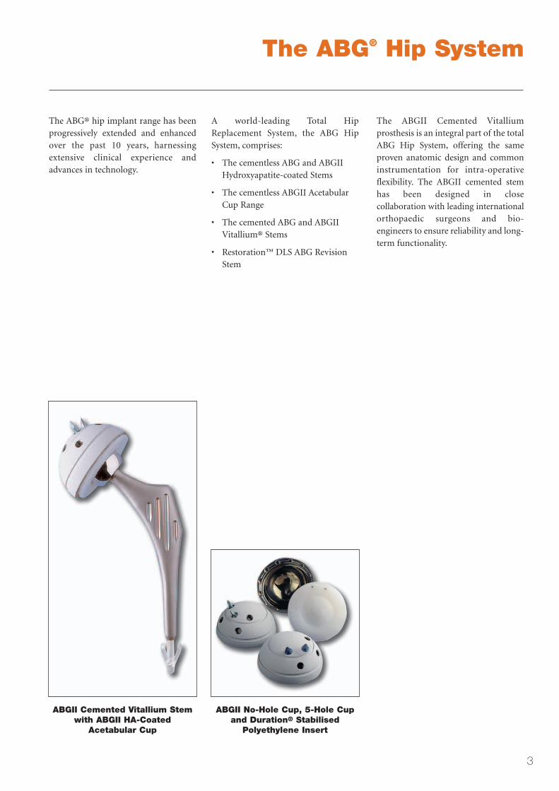
The ABGII Cemented Vitalliumprosthesis is an integral part of the totalABG Hip System, offering the sameproven anatomic design and commoninstrumentation for intra-operativeflexibility. The ABGII cemented stemhas been designed in closecollaboration with leading internationalorthopaedic surgeons and bio-engineers to ensure reliability and long-term functionality.
ABGII Cemented Vitallium Stemwith ABGII HA-Coated
Acetabular Cup
ABGII No-Hole Cup, 5-Hole Cupand Duration® Stabilised
Polyethylene Insert

The ABG®IICemented Femoral Stem
4
The ABG®II Hip System allows thesurgeon to choose between a cementedor a cementless ABG implant, to suitthe individual patient’s needs and tocater for conditions such as poor bonestock.
The actual choice may be made duringsurgery, since the same instrumentationis used for implantation of thecemented and the cementless stem.
Optimised for cemented procedures,the ABGII Cemented Vitallium® stemdesign provides the followingadvantages in clinical use:
Anatomic Stem
Excellent primary stability is achievedthrough the ABG stem shape. Theanatomic shape results in proximalload transfer.
This ensures normal stress distribution,maintaining healthy bone in theproximal femur.
Forged Vitallium® Alloy
The proprietary Stryker cobalt chromealloy provides:
• Proven compatibility withcemented applications
• High strength for loading
• Better resistance to abrasion
• Durability
Conical, Distally Flattened Stem
• Reduced metal volume,compared with the cementlessstem; fits inside the broachprofile
• Allows easier insertion into thecement mantle, and compressesthe cement
• May be used with a distal stemPMMA centraliser to ensurecorrect positioning
Flared Metaphyseal Portion
• Preserves the anatomicalfeatures of the cementless stem
• Helps the implant to sitcorrectly in the metaphysis
• Reduced metal volume leavesvital space for the cementmantle
Proximal Vertical Grooves
The grooves allow for smooth cementflow, and increase the total metaphysealsurface area of the implant.
Proximal stem with verticalgrooves
Distal stem with centraliser Flared metaphyseal geometryof stem

The ABG®IICemented Femoral Stem
Elliptical Cross-Section
The non-cylindrical shape assistsstability by preventing rotation of thestem.
Satin Finish
The satin surface minimisesmicromotion of the stem andmaintains the mechanical engagementof the stem in the cement mantle.
Range of ABG®II Cemented Stems
There are six anatomical stem sizes, in left and right versions.
The stems may be used with two different cementing techniques:
• Thin-layer cement mantle (Self-Locking Mantle)
• Thicker, continuous, all-round cement mantle (Full Mantle)
By selecting the appropriate stem and broach combination, either the self-locking or the full cement mantle can be used.
ABGII Cemented StemSize (Left & Right) 2 3 4 5 6 7
Stem Length (mm) 100 110 115 120 125 135
Distal Diameter (mm) 8.3 8.5 8.5 9.5 10.5 11.5
Self-Locking Mantle
Stem size same as Broach size
ABG II Cemented Stem®
Full Cement Mantle
Stem size smaller than Broach size
ABG II Cemented Stem®
5

Pre-Operative Planning
6
The surgical protocol for implantingthe ABG®II Cemented Vitallium® stemis exactly the same as that used for thecementless stem, up to the implant sizeselection stage.
A space has to be created toaccommodate the implant and itscement mantle, with interdigitation ofthe cement into the cancellous bone.
Pre-Operative Planning
Templating is an essential step in theprocedure and will assist with:
• Selection of final broach size
• The femoral neck resection level
• Control of limb length, byindicating the required femoralhead neck length
Pre-operative planning is done withstem templates with a magnificationfactor of 1.15. The templates are laidover A-P femoral radiographs whichhave the same factor (Fig. 1 & 2).
The proximal shoulder of the stem (D)should be at the level of the digital fossa(d). The inferolateral part (E) (the"elbow" of the prosthesis) is supportedagainst the inferolateral border of thegreater trochanter (e), preserving thecancellous bone near the cortex.
Once metaphyseal fill has beenestablished, the diaphyseal pattern ischecked to see whether reaming will benecessary. Reaming will only be neededin very rare cases.
The femoral neck osteotomy is definedby the upper points C (neck point) andD (digital point) shown on thetemplates; the level is provided by thedistance measured from the mostproximal point of the head or of thelesser trochanter (st).
X-ray templates are available for theABGII Acetabular Cup. Pre-operativeplanning of the cup establishes thecentre of rotation of the implant; thismust come as close as possible to thenormal anatomical geometry. The necklength may be varied to reach thedesired dimensions. However,following acetabular reaming atsurgery the templated cup size mayneed modifying.
It should be noted that pre-operativeplanning is done exclusively on A-Pview films, since lateral films are notreliable enough for use in templating.
The final implant size will be chosenintraoperatively, as the conditionsencountered during surgery mayrequire a size other than the templatedsize.
Fig. 1 X-ray with landmarks
d
ce
t
st
Fig. 2 X-ray with templateshowing landmarks
10
10
Ø8.5mm
3
LEFT 4845-0-923RIGHT 4845-0-913
D
E
T
t
C
st
d
ce

Pre-Operative PlanningCement Mantle & Stem/Broach Selection
7
ABG II Cemented RangeSelf-Locking Mantle
Broaches
Stems
Self-Locking Mantle Stem Size Same as Broach Size
3
3
2
2 4
4
5
5
6
6
7
7
Fig. 3 Broach and stem selection for self-locking mantle
10
10
Ø9.1mm
10
10
Ø8.5mm
3 3
RIGHT 48450913
RIGHT 48450913
Fig. 4 ABGll Cemented Stemtemplate for self-locking
cement mantle
Full Cement Mantle
Broaches
Stems
Full Cement Mantle Stem Size Smaller than Broach Size
4
3
3
2
5
4
6
5
7
6
8
7
ABG II Cemented Range
Fig. 5 Broach and stem selection for full cement mantle
RIGHT 48450914
RIGHT 48450913
4 3
10
10
Ø8.5mm
10
10
Ø10.1mm
Fig. 6 ABGll Cemented Stemtemplate for full cement mantle
SELF-LOCKING
CEMENT MANTLE
FULL CEMENT
MANTLE
• Self–Locking Cement Mantle
Surgeons who wish to use thin-layercementing (self-locking of the stem)should choose an implant of thesame size as that of the final broach.Please note that a thin cementmantle option is not possible if a size8 broach is selected, as a size 8 stemis not available.
• Full Cement Mantle
Surgeons who wish to use a thickercement mantle should select animplant one size smaller than thefinal broach size. Please note that afull cement mantle option is notpossible if a size 2 broach is selected,as a size 1 stem is not available.

Surgical ProtocolOverview of Surgical Protocol
8
The Surgical Protocol for theinsertion of the ABG®II CementedVitallium® Stem involves thefollowing steps:-
• Neck resection
• Cup insertion
• Opening of the proximal femur
• Flexible reaming of the femur,if necessary
• Preparation of metaphysealimplant bed with broach/trials
• Trial reduction
• Cementing and insertion ofdefinitive implant
• Final reduction
• Post-operative management
Patient Positioning
The hip may be accessed via most ofthe conventional approaches.
The technique described here uses thelateral (Hardinge) approach.
The patient is placed on his or her side,on an ordinary operating table. Thepelvis is immobilized between a pubicand a sacral support, allowing freeflexion and abduction of the hip. The“lower” (non-operated) leg is placed ontwo pads, with the hip in extension andthe knee slightly flexed. A laterallongitudinal incision is made, centredover the greater trochanter (Fig. 7).
It may be useful to establish thelandmarks for limb length at this stage.This may be done by inserting one pinabove the acetabulum and another pinon the greater trochanter andmeasuring the distance between thetwo points. This distance should bechecked before the resection of thefemoral head and again after the trialreduction. The measurement obtainedat the end of the procedure mustcorrespond with the length definedduring pre-operative planning.
Fig. 7

Surgical Protocol
9
Neck Osteotomy
The cut with the oscillating saw isstarted at the calcar, at the pointdetermined during templating.
Anterolateral Approach
With an anterior approach theresection is started at the calcar, at apoint determined from the distance ofthe top of the femoral head, duringtemplating. The resection involves asingle cut, which is taken to the base ofthe medial face of the greatertrochanter.
The greater trochanter is carefullypreserved during the procedure.
Posterolateral Approach
With a posterior approach, resectioninvolves two cuts:
• A first cut along an oblique lineon the back of the femoral neck;this does not require anyanteversion.
• A second, vertical cut, whichruns parallel to the medial faceof the greater trochanter and isrouted upwards from the digitalfossa.
Fig. 8 Neck osteotomy, usingAnterolateral approach
Fig. 9 Neck osteotomy, usingPosterolateral approach
60°
30°

Surgical Protocol
10
Fig. 10
Insertion of the Cup
Following neck resection, theacetabulum is exposed and debrided,removing any osteophytes. The cup isinserted with a mean anteversion of 15˚(the angle will vary as a function of thesurgical approach used). Further detailsconcerning cup implantation can befound in the Surgical Protocol for theABG®II cup (available from Stryker).
Opening of the Proximal Femur
The opening is made with a box chiselof a size corresponding the intendedimplant and broach size (Fig. 10).
In order to prevent the implant beingpositioned in varus, the chisel shouldbe introduced laterally, against themedial face of the greater trochanter inthe digital fossa, and a 1-2cm wedge ofcancellous bone should be removed.Chisel 8mm 12mm 16mm
Corresponding Broaches
2, 3 4, 5, 6 7, 8

Surgical Protocol
11
ABG®II Broaches/TrialsBroach Size (Left & Right) 2 3 4 5 6 7 8
Broach Length (mm) 102 112 117 122 127 137 147
Distal Diameter (mm) 8.6 9.1 10.1 11.3 12.3 13.0 14.1
Minimum Reaming Diameter* (mm) 9.0 10 11 13 14 14 15
*If necessary due to patient anatomy
Fig. 11
Broaching
The smallest broach (right or left, asappropriate) is inserted to prepare thefemoral canal (Fig. 11).
The broach must be positioned asvertically as possible, by enteringlaterally at the level of the digital fossa;the cancellous bone at the calcar shouldbe spared as much as possible, since itprovides a safeguard against varuspositioning.
If the femoral canal is very narrow,calibration reaming may be necessaryto determine the diameter of the canal.
Next, the broach/trials are inserted intothe metaphysis.
Surgeons who wish to use thin-layercementing should choose an implant ofthe same size as that of the finalbroach. Surgeons who wish to use athicker cement mantle should choosean implant one size smaller than thatof the final broach.

Surgical Protocol
12
Fig. 12
Trial Reduction
A plastic trial head of the required sizeis placed on the broach/trial, and a trialreduction is performed to check hipstability and limb length (Figs. 12 & 13).
This is not a substitute for the test to beperformed once the definitive stem hasbeen cemented in.
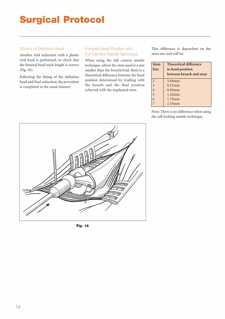
Please refer to page 14 for informationrelating to head position when usingthe full cement mantle technique.
Fig. 13

Surgical Protocol
13
Fig. 15
Cementing and Insertion of theDefinitive Stem
This part of the procedure involves thefollowing stages (Figs. 14 & 15):-
• Plugging of the distal femoralcanal 1cm beyond the stem tipor the distal centraliser, with acement restrictor strong enoughto withstand the pressureexerted during cement insertion
• Insertion of cement from distalto proximal level, using acement gun
SURGICAL SIMPLEX® CEMENT
• Pressurisation of the cement
• Insertion of the stem with thedistal centraliser (optional), carebeing taken to ensure the properpositioning of the stem at theproximal end;
• Keeping the stem steady whilstthe cement is polymerising
Fig. 14
Surgical Protocol
14
Stem Theoretical differenceSize in head position
between broach and stem
2 3.64mm3 0.57mm4 0.94mm5 1.42mm6 1.75mm7 2.16mm
Note: There is no difference when usingthe self-locking mantle technique.
Fig. 16
Choice of Definitive Head
Another trial reduction with a plastictrial head is performed, to check thatthe femoral head neck length is correct(Fig. 16).
Following the fitting of the definitivehead and final reduction, the procedureis completed in the usual manner.
Femoral Head Position withFull Cement Mantle Technique
When using the full cement mantletechnique, where the stem used is a sizesmaller than the broach/trial, there is atheoretical difference between the headposition determined by trialling withthe broach and the final positionachieved with the implanted stem.
This difference is dependent on thestem size and will be:

Surgical Protocol
15
Vitallium® (CoCr) heads available:
Diameter 22.2mm 28mm 32mm
Short necks -4 -4
Standard necks 0 0 0
Long necks +3 +4, +8 +4, +8
Stryker V40™ Heads
The cemented ABG®II prosthesis iscompatible only with the Stryker rangeof V40™ femoral heads. The V40 headshave a 5˚40´ taper and are available inVitallium® (Cobalt Chrome).
Postoperative Management
The patients may be mobilised and allowed to weight-bear within 1-3 days post-operatively. Generally, walking aids are used for the first month following surgery.

Femoral Implants Acetabular Implants
16
ABG®II Cemented Vitallium Femoral Stems*LEFT RIGHT
CAT. NO. SIZE CAT. NO.
48460202 2 4846010248460203 3 4846010348460204 4 4846010448460205 5 4846010548460206 6 4846010648460207 7 48460107
ABGII Broaches/TrialsLEFT RIGHT
CAT. NO. SIZE CAT. NO.
48450922 2 4845091248450923 3 4845091348450924 4 4845091448450925 5 4845091548450926 6 4845091648450927 7 4845091748450928 8 48450918
V40™ Femoral Heads, 5°40´ TaperHEAD NECK VITALLIUM
DIAMETER LENGTH HEAD(mm) (mm) IMPLANT NO.
22.2 0 62605122 22.2 +3 62605222 28 -4 62605028 28 0 62605128 28 +4 62605228 28 +8 62605328 32 -4 62605032 32 0 62605132 32 +4 62605232 32 +8 62605332
Head TrialsPLASTIC HEAD NECK
CONICAL DIAMETER LENGTH TRIAL (mm) (mm)
62648122 22.2 062648222 22.2 +362648028 28 -462648128 28 062648228 28 +462648328 28 +862648032 32 -462648132 32 062648232 32 +462648332 32 +8
ABGII 5-Hole CupIMPLANT OUTER CUP TRIAL
CAT. NO. DIAMETER CAT. NO.
(mm)
48401042 42 4849004248401044 44 4849004448401046 46 4849004648401048 48 4849004848401050 50 4849005048401052 52 4849005248401054 54 4849005448401056 56 4849005648401058 58 4849005848401060 60 4849006048401062 62 4849006248401064 64 4849006448401066 66 4849006648401068 68 4849006848401070 70 4849007048401072 72 4849007248401074 74 48490074
ABGII No-Hole Cup IMPLANT OUTER CUP TRIAL
CAT. NO. DIAMETER CAT. NO.
(mm)
48402042 42 4849004248402044 44 4849004448402046 46 4849004648402048 48 4849004848402050 50 4849005048402052 52 4849005248402054 54 4849005448402056 56 4849005648402058 58 4849005848402060 60 4849006048402062 62 4849006248402064 64 4849006448402066 66 4849006648402068 68 4849006848402070 70 48490070
For use with ABGII No-Hole Cups - SpikeCAT. NO.
48402008 ABGII NO-HOLE SPIKE
For use with ABGII 5-Hole Cups - Spike/ScrewCAT. NO.
48400000 ABG OBTURATOR SCREW 48400007 ABG CUP SPIKE 7mm48400009 ABG CUP SPIKE 9mm48406512 ABG CUP SCREW 12mm48406515 ABG CUP SCREW 15mm48406520 ABG CUP SCREW 20mm48406525 ABG CUP SCREW 25mm48406530 ABG CUP SCREW 30mm48406535 ABG CUP SCREW 35mm48406540 ABG CUP SCREW 40mm48406545 ABG CUP SCREW 45mm48406550 ABG CUP SCREW 50mm48406555 ABG CUP SCREW 55mm

Acetabular Implants
17
ABG®II Inserts, Duration® Stabilised UHMWPE (Only for use with ABGII Cups)
22.2mm Standard
IMPLANT OUTER CUP TRIAL CAT. NO. DIAMETER CAT. NO.
(mm)
48442242 42 48482242 48442244 44 48482244 48442246 46 48482246 48442248 48 48482248 48442250 50 48482250 48442252 52 48482252 48442254 54 48482254 48442256 56 48482256 48442258 58 48482258 48442260 60 48482260 48442262 62 48482262 48442264 64 48482264 48442266 66 48482266 48442268 68 48482268 48442270 70 48482270
28mm Standard
IMPLANT OUTER CUP TRIAL CAT. NO. DIAMETER CAT. NO.
(mm)
48442846 46 48482846 48442848 48 48482848 48442850 50 48482850 48442852 52 48482852 48442854 54 48482854 48442856 56 48482856 48442858 58 48482858 48442860 60 48482860 48442862 62 48482862 48442864 64 48482864 48442866 66 48482866 48442868 68 48482868 48442870 70 48482870 48442872 72 48482872 48442874 74 48482874
32mm Standard
IMPLANT OUTER CUP TRIAL CAT. NO. DIAMETER CAT. NO.
(mm)
48443250 50 48483250 48443252 52 48483252 48443254 54 48483254 48443256 56 48483256 48443258 58 48483258 48443260 60 48483260 48443262 62 48483262 48443264 64 48483264 48443266 66 48483266 48443268 68 48483268 48443270 70 48483270 48443272 72 48483272 48443274 74 48483274
22.2mm Hooded
IMPLANT OUTER CUP TRIAL CAT. NO. DIAMETER CAT. NO.
(mm)
48452242 42 48492242 48452244 44 48492244 48452246 46 48492246 48452248 48 48492248 48452250 50 48492250 48452252 52 48492252 48452254 54 48492254 48452256 56 48492256 48452258 58 48492258 48452260 60 48492260 48452262 62 4849226248452264 64 48492264 48452266 66 48492266 48452268 68 48492268 48452270 70 48492270
28mm Hooded
IMPLANT OUTER CUP TRIAL CAT. NO. DIAMETER CAT. NO.
(mm)
48452846 46 48492846 48452848 48 48492848 48452850 50 48492850 48452852 52 48492852 48452854 54 48492854 48452856 56 48492856 48452858 58 48492858 48452860 60 48492860 48452862 62 48492862 48452864 64 48492864 48452866 66 48492866 48452868 68 48492868 48452870 70 48492870 48452872 72 48492872 48452874 74 48492874
32mm Hooded
IMPLANT OUTER CUP TRIAL CAT. NO. DIAMETER CAT. NO.
(mm)
48453250 50 48493250 48453252 52 48493252 48453254 54 48493254 48453256 56 48493256 48453258 58 48493258 48453260 60 48493260 48453262 62 48493262 48453264 64 48493264 48453266 66 48493266 48453268 68 48493268 48453270 70 48493270 48453272 72 48493272 48453274 74 48493274
22.2mm Cylindro-Spherical
IMPLANT OUTER CUP TRIALCAT. NO. DIAMETER CAT. NO.
(mm)
48462242 42 4846124248462244 44 4846124448462246 46 4846124648462248 48 4846124848462250 50 4846125048462252 52 4846125248462254 54 4846125448462256 56 4846125648462258 58 4846125848462260 60 4846126048462262 62 4846126248462264 64 4846126448462266 66 4846126648462268 68 4846126848462270 70 48461270

79121520253035404550
50 40 30 20 10
VIS
Ø 6
PO
INT
ES
79121520253035404550
50 40 30 20 10
VIS
Ø 6
PO
INT
ES
79121520253035404550
50 40 30 20 10
VIS
Ø 6
PO
INT
ES
79121520253035404550
50 40 30 20 10
VIS
Ø 6
PO
INT
ES
79121520253035404550
50 40 30 20 10
VIS
Ø 6
PO
INT
ES
79121520253035404550
50 40 30 20 10
VIS
Ø 6
PO
INT
ES
79121520253035404550
50 40 30 20 10
VIS
Ø 6
PO
INT
ES
79121520253035404550
50 40 30 20 10
VIS
Ø 6
PO
INT
ES
79121520253035404550
50 40 30 20 10
VIS
Ø 6
PO
INT
ES
79121520253035404550
50 40 30 20 10
VIS
Ø 6
PO
INT
ES
79121520253035404550
50 40 30 20 10
VIS
Ø 6
PO
INT
ES
79121520253035404550
50 40 30 20 10
VIS
Ø 6
PO
INT
ES
ABG®II Acetabular Instruments Storage
48496200
ABGII Acetabular Cup Trials, InsertTrials and Spike Tray Storage andSterilisation Case (Empty)
48496100
Acetabular Reamers Sterilisation andStorage Case (Empty)
79121520253035404550
50 40 30 20 10
VIS
Ø 6
PO
INT
ES
79121520253035404550
50 40 30 20 10
VIS
Ø 6
PO
INT
ES
For use with ABG®II Inserts
ABGII Impactor Flanges
48494222For Standard inserts ID 22.2mm
48494228
For Standard inserts ID 28mm
48494232
For Standard inserts ID 32mm
48494322
For Hooded inserts ID 22.2mm
48494328
For Hooded inserts ID 28mm
48494332
For Hooded inserts ID 32mm
18
ABGTP02E02
ABGII Standard PE Cup100% Magnification
ABGTP06E02
ABGII Standard PE Cup110% Magnification
ABGTP10E02
ABGII Standard PE Cup115% Magnification
ABGTP14E02
ABGII Standard PE Cup120% Magnification
ABGTP03E02
ABGII Hooded PE Cup100% Magnification
ABGTP07E02
ABGII Hooded PE Cup110% Magnification
ABGTP11E02
ABGII Hooded PE Cup115% Magnification
ABGTP15E02
ABGII Hooded PE Cup120% Magnification
For use with ABG®II Cups
79121520253035404550
50 40 30 20 10
VIS
Ø 6
PO
INT
ES
79121520253035404550
50 40 30 20 10
VIS
Ø 6
PO
INT
ES
79121520253035404550
50 40 30 20 10
VIS
Ø 6
PO
INT
ES
79121520253035404550
50 40 30 20 10
VIS
Ø 6
PO
INT
ES
79121520253035404550
50 40 30 20 10
VIS
Ø 6
PO
INT
ES
79121520253035404550
50 40 30 20 10
VIS
Ø 6
PO
INT
ES
79121520253035404550
50 40 30 20 10
VIS
Ø 6
PO
INT
ES
79121520253035404550
50 40 30 20 10
VIS
Ø 6
PO
INT
ES
48390100
Reamer Handle with HudsonConnection
48390110
Reamer Handle with AO TipConnection
02881010
Hudson/Jacobs Adaptor
48496060
Impactor for Cup
48496080
Orientator Ring
48491000
Cup Extractor
OUTER OUTERCAT.NO. DIA. CAT.NO. DIA.
48390038 38mm 48390058 58mm48390040 40mm 48390060 60mm48390042 42mm 48390062 62mm48390044 44mm 48390064 64mm48390046 46mm 48390066 66mm48390048 48mm 48390068 68mm48390050 50mm 48390070 70mm48390052 52mm 48390072 72mm48390054 54mm 48390074 74mm48390056 56mm 48390076 76mm
Acetabular Reamers
X-ray Templates
Acetabular Instrumentation
48496070
Cup Holder
48498353
ABGII Hexagonal Socket Screwdriver
1826350
Hexagonal Screwdriver, Standard
48496010
ABGII No-Hole Cup Spikedriver
48492013
Standard Screw Holding Forceps
48492014
Curved Screw Holding Forceps
48493000
Double Drill Guide
48493015
Flexible Drill 3.2mm Diameter 15mm Active Length
48493030
Flexible Drill 3.2mm Diameter 30mm Active Length
48492012
Screw Depth Gauge
48496050
ABGII Spike, Screw, ObturatorSterilisation Case

19
Modular Hollow ChiselsCAT. NO. SIZE
48498008 8mm
48498012 12mm
48498016 16mm
ABG Flexible ReamersLength 400mmCAT. NO. DIA.
02224006 8mm
02224008 9mm
02224010 10mm
02224012 11mm
02224014 12mm
02224016 13mm
02224018 14mm
02224020 15mm
02224022 16mm
02224024 17mm
02224026 18mm
49001530
Flexible Reamer Guide Length 520mm, Diameter 3.2mm
02520010
Trinkle Jacobs Adaptor
44000420
AO/Trinkle Adaptor
48424002
Diameter gauge for ABGII Broachesand Reamers
7300001Hexagonal Screwdriver for ABGIIBroach Holder (Anterior)
48421000Femoral Impactor
48422000Reduction Guide
48498001Modular Femoral Extractor V40Spigot (for plastic spigot protector)
48498002Modular Femoral Extractor V40Spigot (Metal)
48496300ABGII Femoral Broaches, Handleand Trial Heads Storage andSterilisation Case (Empty)
48496320ABGII Femoral Reamer andInstrumentation Tray (Empty) Fitsinside # 48496300 case
ABG®II Femoral Instruments Storage
49011530
Posterior Approach ABGII BroachHandle (V40 Spigot)
49011540Anterior Approach ABGII BroachHandle (V40 Spigot)
49011600Posterior Approach 130° BroachHandle (V40™ Spigot)
ABGTP17E01
ABGII Cemented Stem15% Magnification(Self-Locking Mantle)
ABGTP18E01
ABGII Cemented Stem 15% Magnification(Full Cement Mantle)
ABGTP19E01
ABGII Cemented Stem 15% Magnification(Full Cement Mantle 2 & 3)
X-ray Templates
Femoral Instrumentation

This document is intended solely for the use of healthcare professionals.
The information presented in this brochure is intended to demonstrate the breadth ofStryker product offerings. Always refer to the package insert, product label and/or userinstructions before using any Stryker product. Products may not be available in allmarkets. Product availability is subject to the regulatory or medical practices thatgovern individual markets. Please contact your Stryker representative if you havequestions about the availability of Stryker products in your area.
Products referenced with ™ designation are trademarks of Stryker.Products referenced with ® designation are registered trademarks of Stryker.
Literature Number: ABGBR03E02BEN14429/REF 1.5 09/05
Copyright © 2004 Stryker
Stryker SACité-CentreGrand-Rue 921820 MontreuxSwitzerland
t : +41 21 966 12 01
f : +41 21 966 12 00
www.europe.stryker.com
http://www.abg2hip.com