Effects of Repair Procedures Applied to...
27
The Joint Advanced Materials and Structures Center of Excellence June 21 st , 2006 Effects of Repair Procedures Applied Effects of Repair Procedures Applied to Composite Airframe Structures to Composite Airframe Structures National Institute for Aviation Research National Institute for Aviation Research Wichita State University Wichita State University
Transcript of Effects of Repair Procedures Applied to...

The Joint Advanced Materials and Structures Center of ExcellenceJune 21st, 2006
Effects of Repair Procedures Applied Effects of Repair Procedures Applied to Composite Airframe Structuresto Composite Airframe Structures
National Institute for Aviation ResearchNational Institute for Aviation ResearchWichita State UniversityWichita State University

2The Joint Advanced Materials and Structures Center of Excellence
Research Team
Principal Investigators & Researchers– Dr. John Tomblin, Wichita State University– Lamia Salah, Wichita State University– Dr. Charles Yang, Wichita State University
FAA Technical Monitor– Peter Shyprykevich
Other FAA Personnel Involved– Curtis Davies, Larry Ilcewicz
Industry Participation– Spirit Aerosystems– Raytheon Aircraft– Adam Aircraft

3The Joint Advanced Materials and Structures Center of Excellence
Objective/ Overview
To assess the effects of different variables on the strength and durability of repairs applied to composite laminate and sandwich structures
Substrate stiffnessLap lengthThicknessRepair materialsCure TemperaturesStatic/ Fatigue Performance
To evaluate the strength and durability of poorly bonded repairs that passed NDI
Poor Surface PreparationPre-bond MoistureImproper CureContamination
To validate existing CACRC standards and provide recommendationspertaining to proper repair process implementationTo develop an analysis method and corresponding failure criteria for structural sizing of bonded repairs

4The Joint Advanced Materials and Structures Center of Excellence
Research Methodology
Task1: to generate baseline static and fatigue repair data for both composite laminate and sandwich coupons using OEM repairs as well as field repairs. Laminate repaired coupons are tested in tension whereas sandwich repaired coupons are tested in compression
Task 2: to evaluate the durability of “poor” bonded repairs that passed NDI (undetected weak repairs). Deviations in process parameters/ contamination will be induced during coupon repair and subsequent mechanical testing will be conducted to assess the static and residual strength after repeated loading.
Task 3: task 2 results will be used to validate CACRC standards required for composite repair and inspection technicians and providing recommendations pertaining to repair process control to ensure repair bond structural integrity
Task4: to validate experimental results using FEM

5The Joint Advanced Materials and Structures Center of Excellence
Relevance to FAA CS & CI
6The Joint Advanced Materials and Structures Center of Excellence
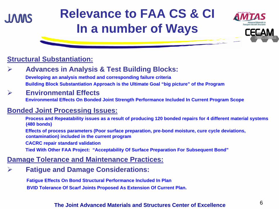
Relevance to FAA CS & CIIn a number of Ways
Structural Substantiation:Advances in Analysis & Test Building Blocks:Developing an analysis method and corresponding failure criteriaBuilding Block Substantiation Approach is the Ultimate Goal “big picture” of the Program
Environmental EffectsEnvironmental Effects On Bonded Joint Strength Performance Included In Current Program Scope
Bonded Joint Processing Issues:Process and Repeatability issues as a result of producing 120 bonded repairs for 4 different material systems (480 bonds)Effects of process parameters (Poor surface preparation, pre-bond moisture, cure cycle deviations, contamination) included in the current programCACRC repair standard validationTied With Other FAA Project: “Acceptability Of Surface Preparation For Subsequent Bond”
Damage Tolerance and Maintenance Practices:Fatigue and Damage Considerations:Fatigue Effects On Bond Structural Performance Included In PlanBVID Tolerance Of Scarf Joints Proposed As Extension Of Current Plan.

7The Joint Advanced Materials and Structures Center of Excellence
Laminate Baseline Repair Data
Panels manufactured and supplied by the OEMOEM Repair
Panels are machined into subpanels, scarfed and repaired using an OEM proprietary debulking procedureRepairs implemented using the laminate parent material as the repair material
Field RepairACG T800/MTM45 unidirectional prepreg with FM300-2U film adhesive
Hexcel M20 prepreg with Metalbond 1515-4 adhesiveAMS 2980 CACRC using G40-800 6k intermediate modulus fibers with Epocast 52A/B Laminating resin

8The Joint Advanced Materials and Structures Center of Excellence
Repair Section
S1
S2 S3
S4 S5
S6
Parent Section
Strain Gage Layout (-30 Scarf Rate Panel 5 & 6)
Scarf Edge
0.5" 0.5"
2"
a = scarf length(approx 7.575)
0.35"
0.35"
b= a/2 - .35
4"
b
b
b a/2
gage length approx 18.634
Baseline Repair Data
Panel Machining and Scarfing
Strain Gage LayoutRepair Panel NDI
1-D Coupon used to isolate parameters/ effects studied

9The Joint Advanced Materials and Structures Center of Excellence
Test Matrix-Laminate
Test Matrix288 coupons are being used to generate baseline static and fatigue data for OEM/field repairsphotogrammetry system is being used to monitor specimen deformation/ strain concentrations in the repairARAMIS strain data validated using strain gagesFatigue coupons are cycled for 165000 cycles and tested for residual strength to demonstrate repair acceptability.
Mechanical TestingStrain Monitoring
using ARAMIS
STATIC FATIGUEPanel # Thickness (in) E (Msi) Scarf Rate RTA RTA
N/A 6 61 7.2 20 6 6
0.1332 30 6 6N/A 6 6
2 9.1 20 6 630 6 6N/A 6 6
3 7.7 20 6 60.2368 30 6 6
N/A 6 64 8.8 20 6 6
30 6 6

10The Joint Advanced Materials and Structures Center of Excellence
Test Matrix- Sandwich
Test Set-Up/ Test Matrix45 coupons will be used to generate
baseline static and fatigue data for OEM/ field repairs
A four point bending beam fixture will be used for loading
Fatigue coupons will be cycled for one lifetime equivalent to 150000 cycles and tested for residual strength to demonstrate repair acceptability.
2-D Taper Sand Region (0.5" overlap)
Exposed Core (3" diameter)
46.00
11.50
5.00 4.007.00
Synspand
Repair Configuration Core Cell Size Repair Material Repair TypeScarf Overlap
(in)
Static
(RTA)
Fatigue
(RTA)Baseline undamaged N/A* 3 6
3/16 Toray T700/2510 PW Prepreg Flush Scarf Repair 0.50 3 62-D External Patch 0.50 3 6
Compression Flush Scarf Repair 0.50 3 6External Patch 0.50 3 6
*Baseline undamaged unrepaired coupon
3/16 CACRC Wet lay-up Repair

11The Joint Advanced Materials and Structures Center of Excellence
Effects of Process Parameters
The quality of training and experience of repair technicians is directly associated with the technician’s successful implementation of a repairRef. John Tomblin et. al “Bonded Repairs of aircraft composite sandwich structures.” FAA AR 03-74Process deviation directly affects the strength of the repairTo investigate the performance of OEM/ field repairs using different methods
CACRC Method
OEMMethod

12The Joint Advanced Materials and Structures Center of Excellence
Effects of Process Parameters
0
20
40
60
80
100
120
Failu
re L
oad
(%)
4"diameter hole
CACRC Picture Frame Shear Elements
undamaged
Airline Depot # 1 Airline Depot # 2 Airline Depot # 3
Boeing prepregrepair
prepreg repair
wet lay-up repair
prepreg repair
wet lay-up repair
wet lay-up repair
prepreg repair
Airline Depot # 4
prepreg repair
wet lay-up repair
BVID

13The Joint Advanced Materials and Structures Center of Excellence
Surface Free Energy by contact Angle Measurement
Deicing FluidSkydrolHydraulic FluidJet FuelWater
A surface with a high surface free energy will produce a good bondSurface Free energy can be measured by measuring surface contact angleScreening study was conducted to determine surface free energy of contaminated surfaces ready for repair (Dr. Bill Stevenson)
Contaminant Exposure Surface Free Energy (mN/m)None N/A 55.16Deicing Fluid 30 days @ RTD 56.29Skydrol 30 days @ RTD 43.83Jet Fuel JP-8 30 days @ RTD 51.74Water (85% @145°F) Saturation 46.4Salt Water 30 days@ RTD 56.41

14The Joint Advanced Materials and Structures Center of Excellence
Effects of Process Parameters-Test Matrix
Mechanical Tests will be conducted to assess the effects of process deviations on these repairs
Load Mode Process Laminate Scarf
Parameters Thickness Rate Static (RTA)Repeated
Loading (RTA)
Surface Preparation
Cure
Tension
Contaminant 1
Contaminant 2
MoistureEffects of Pre-bond
Effects of Poor
Effects of Improper
Effects of Surface
Effects of Surface
20 6 6
20 6 6
20 6 6
20 6 6
20 6 6
20 6 6
20 6 6
20 6 6
0.1332
0.2368
0.1332
0.2368
0.1332
0.2368
0.1332
0.2368
OEM RepairQuantity of Test
0.1332
0.2368
20 6 6
20 6 6

15The Joint Advanced Materials and Structures Center of Excellence
Laminate Mechanical Test Data Static Test Results
Failure Loads vs. Scarf Rates (Panels 1 & 2)
0
10000
20000
30000
40000
50000
60000
0 10 20 30 40
Scarf Rates
Failu
re L
oads
(lbs
)
Panel 1, E=7.2Msi, RTAPanel 2, E=9.1Msi, RTA
Slight increase in load carrying capability for panel 1 compared to panel 2

16The Joint Advanced Materials and Structures Center of Excellence
Laminate Mechanical Test Data Initial Results
Static/ Residual Strength vs. Scarf Rates (Panel 1)
0
10000
20000
30000
40000
50000
60000
0 10 20 30 40
Scarf Rates
Failu
re L
oads
(lbs
)
Panel 1, E=7.2Msi, RTAPanel 1, E=7.2Msi, RTF
20% strength degradation
Coupons fatigued at a strain level equivalent to 3000 microstrain for 165000 cycles

17The Joint Advanced Materials and Structures Center of Excellence
Laminate Mechanical Test Data Results
Static/ Residual Strength vs. Scarf Rates (Panel 2)
0
10000
20000
30000
40000
50000
60000
0 10 20 30 40
Scarf Rates
Failu
re L
oads
(lbs
)
Panel 2, E=9.1Msi, RTAPanel 2, E=9.1Msi, RTF
17% strength degradation
Coupons fatigued at a strain level equivalent to 3000 microstrain for 165000 cycles
18The Joint Advanced Materials and Structures Center of Excellence
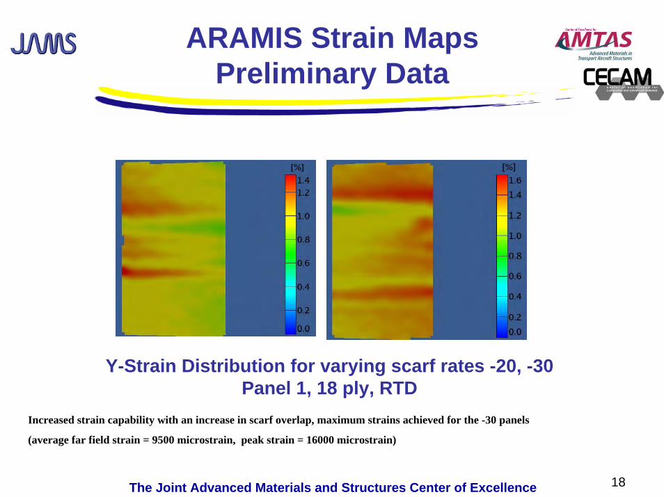
ARAMIS Strain MapsPreliminary Data
Y-Strain Distribution for varying scarf rates -20, -30Panel 1, 18 ply, RTD
Increased strain capability with an increase in scarf overlap, maximum strains achieved for the -30 panels
(average far field strain = 9500 microstrain, peak strain = 16000 microstrain)

19The Joint Advanced Materials and Structures Center of Excellence
ARAMIS Strain MapsPreliminary Data
Y-Strain Distribution for varying scarf rates -20, -30Panel 2, 18 ply, RTD
Increased strain capability with an increase in scarf overlap, maximum strains achieved for the -30 panels
(average far field strain = 8500 microstrain, peak strain = 11000 microstrain)Stiffer panel (panel 2) has lower strain to failure than the softer panel (panel 1)

20The Joint Advanced Materials and Structures Center of Excellence
Strain Variation vs Stiffness (Scarf Edge)
Scarf Edge Strains Versus Panel Stiffness (20 : 1)
0
2000
4000
6000
8000
10000
12000
14000
16000
6.0 6.5 7.0 7.5 8.0 8.5 9.0 9.5 10.0Stiffness (Msi)
Scar
f Edg
e St
rain
Aramis Data Panel 2 Location 4Aramis Data Panel 1 Location 4Strain Gage Data Panel 2 Location 4Strain Gage Data Panel 1 Location 4Strain Gage Data Panel 1 Location 5Aramis Data Panel 1 Location 5Aramis Data Panel 2, Location 5Strain Gage Data Panel 2 Location 5

21The Joint Advanced Materials and Structures Center of Excellence
Failure Modes/ Fractography
SEM AnalysisFailure Mode: combination of a cohesive failure of the adhesive and interlaminarfacing failure of the laminate indicative of a strong bond
SEM analysis shows fiber fracture, brittle/ shear failure of the adhesive

22The Joint Advanced Materials and Structures Center of Excellence
Analytical Validation2-D FEA
2-Dimensional Dynamic Finite Element Models
Adhesive Failure Criterion: Equivalent Plastic Strain=0.25
90-Deg Ply Failure Criterion: von Mises Equivalent Stress = 19 ksi
Scarf Joint
Stepped Joint
OPT53 2D Models Test (lbf)
ABAQUS Data
Deviation %
OPT53-1 Scarf 30,186.1 3.8
OPT53-1 Stepped 29,653.6 1.9
OPT53-2 Scarf 27,006.5 6.8
OPT53-2 Stepped 23,930.8 -5.4
OPT53-3 Scarf 55,901.2 -1.5
OPT53-3 Stepped 49,062.7 -13.6
OPT53-4 Scarf 54,773.3 0.1
OPT53-4 Stepped 49,751.6 -9.2
OPT53-5 Scarf 71,102.0 -8.5
OPT53-5 Stepped 74,264.6 -4.4
OPT53-6 Scarf 75,899.5 6.4
OPT53-6 Stepped 75,036.5 5.271,333.3
77,678.3
54,765.6
56,768.3
25,292.0
29,089.3

23The Joint Advanced Materials and Structures Center of Excellence
Analytical Validation
3-D Finite Element Model of a Scarf Joint
Total Elements
Total Nodes
OPT53-1 30,090 35,824
OPT53-2 36,900 44,448
OPT53-3 69,300 79,136
OPT53-4 65,655 75,680
OPT53-5 114,855 129,504
OPT53-6 128,535 144,8003-D FEA used to show edge effects and initiate failure around the scarf edge

24The Joint Advanced Materials and Structures Center of Excellence
Analytical Validation
0.007
0.008
0.009
0.010
0.00 1.03 2.07 3.10
Overlap X-Coordinate (in)
Stra
ins
ε11
(in/in
)
Test Data 1 (RF1=71,333 lbf)Test Data 2 (RF1=71,333 lbf)OPT53-6 3-D COM-QUA Static (F=71,333 lbf)OPT53-6 3-D COM-ENG-QUA Static (F=71,333 lbf)
Surface Strain Comparison between 3-D FE Model and ARAMIS Data (OPT53-6)

25The Joint Advanced Materials and Structures Center of Excellence
Analytical Validation
90-degree Ply Failure (Effective Stress Limit =19,000 psi)Adhesive Shear Failure PEEQ = 0.285
Test DataABAQUS
DataDeviation
% ν90
OPT53-1 COM-QUA 29,089.3 lbf 24,635.4 lbf -15.3 0.200
OPT53-2 COM-QUA 25,292.0 lbf 24,472.2 lbf -3.2 0.150
OPT53-3 COM-QUA 56,768.3 lbf 57,532.4 lbf 1.3 0.017
OPT53-4 COM-QUA 54,765.6 lbf 54,444.6 lbf -0.6 0.017
OPT53-5 COM-QUA 77,678.3 lbf 71,041.0 lbf -8.5 0.015
OPT53-6 COM-QUA 71,333.3 lbf 66,171.2 lbf -7.2 0.017
90-degree Ply Failure (Effective Stress Limit =15,000 psi)Adhesive Shear Failure PEEQ = 0.285
Test DataABAQUS
DataDeviation
% ν90
OPT53-3 COM-QUA 56,768.3 lbf 55,998.0 lbf -1.4 0.017
OPT53-4 COM-QUA 54,765.6 lbf 52,149.0 lbf -4.8 0.017
90-degree plies modeled as isotropic since ABAQUS only offers stress failure criteria for isotropic materials

26The Joint Advanced Materials and Structures Center of Excellence
Status To Date
Laminate mechanical Testing to generate baseline repair data for various repair materials in progressLaminate repair using ACG MTM45/T800 in progressPanel Machining to generate mechanical data for contaminated coupons is in progressScreening panels for the sandwich configuration have been tested and are being resized to induce failure in the repairImproved analytical test results correlation with experimental data (3D FEM model)

27The Joint Advanced Materials and Structures Center of Excellence
A Look Forward/ Future Plans
Benefits To Aviation:To assess the effects of surface contamination and process variations on the performance of bonded repairsTo develop rigorous repeatable repair processes that ensure structural integrity of bonded repairsTo gain confidence in bonded structural repairsTo provide guidance for analytical modeling of repairs


![EFFECT OF SURFACE CONTAMINATION ON ...depts.washington.edu/amtas/events/jams_14/papers/...previous papers [26, 27]. Contaminated and non-contaminated specimens will be fatigued in](https://static.fdocuments.in/doc/165x107/607b0607abacf7659b18c5d2/effect-of-surface-contamination-on-depts-previous-papers-26-27-contaminated.jpg)