
Effects of Outlet Boundary Conditions on the Reacting Flow Field in a Swirl-Stabilized Burner at Dry...
9
Steffen Terhaar 1 e-mail: [email protected] Bernhard C. Bobusch Christian Oliver Paschereit Chair of Fluid Dynamics Hermann-Fo ¨ttinger-Institut, Technische Universita ¨t Berlin, Mu ¨ller-Breslau-Str. 8, 10623 Berlin, Germany Effects of Outlet Boundary Conditions on the Reacting Flow Field in a Swirl-Stabilized Burner at Dry and Humid Conditions During the design and testing process of swirl-stabilized combustors, it is often impractical to maintain identical outlet boundary conditions. Furthermore, it is a common practice to intentionally change the acoustic boundary conditions of the outlet in order to suppress thermoacoustic instabilities. In the presented work the susceptibility of the reacting flow field to downstream perturbations is assessed by the application of an area contraction at the outlet. Since combustion and fuel composition are shown to be important parameters for the influence of the boundary conditions on the flow field, highly steam diluted flames are investigated in addition to dry flames at different equivalence ratios and degrees of swirl. The applied measurement techniques include particle image velocimetry, laser doppler velocimetry, and emission analysis. The results reveal a clear correlation of the susceptibility of the flow field to downstream perturbations to both the inlet swirl number and the amount of dilatation caused by the flame. The concept of an effective swirl number downstream of the flame is applied to the results and is proven to be the dominating param- eter. A theoretical explanation for the influence of this parameter is provided by the usage of the well known theory of subcritical and supercritical swirling flows, where perturba- tions can propagate upstream solely in subcritical flows via standing waves. Knowledge of the flow state is of particular importance for the evaluation of combustion tests with differ- ing exit boundary conditions and the results emphasize the need for realistic exit boundary conditions for numerical simulations. [DOI: 10.1115/1.4007165] 1 Introduction Swirl-stabilized combustion systems are widely used in modern gas turbines to enhance mixing, reduce pollutants, and improve flame stability [1]. Numerous studies have been carried out inves- tigating the combustion process, thermoacoustic behavior of the flame, and the flow field inside the combustor. Recent comprehen- sive reviews on the topic of combustion dynamics and thermo- acoustics were made by Huang et al. [2] and Lieuwen and Yang [3], respectively. A typical combustor design and testing process involves several test facilities ranging from water tunnel facilities to multiburner arrangements including atmospheric and pressurized combustion test rigs (e.g., [4,5]). It is important that the results can be trans- ferred from one stage to another. Naturally, the outlet boundary conditions cannot always be kept constant due to different test rig restrictions. Furthermore, to suppress self-excited thermoacoustic instabilities, it is common practice to intentionally change the acoustic outlet boundary conditions, for instance, by means of an area contraction (e.g., [6–8]). The basic theory about the upstream effect of perturbations in swirling flows goes back to the work of Squire [9] and Benjamin [10] on vortex breakdown. Both used the approach of a cylindrical vortex flow with a superposed disturbance of small amplitude. If the mean flow field can sustain long inertia waves, perturbations can be transmitted upstream and the flow state is called subcriti- cal. If the waves are swept downstream, the flow is termed super- critical and perturbations only affect the local flow. Both Squire and Benjamin related the phenomenon of vortex breakdown to a change from a supercritical to a subcritical flow state. Escudier and Keller [11] used the criticality theory to explain the different levels of influence of an area contraction at the outlet on the isothermal swirling flow field in a vortex tube at low and high swirl numbers. They assume that due to viscous effects, the subcritical flow after the vortex breakdown can either remain sub- critical or recover to a supercritical state depending on the initial level of swirl and the length of the vortex tube. Carrying out LDA measurements in a water tunnel facility, they showed that for low levels of swirl, the application of an outlet area contraction has a negligible effect on the flow field. Hence, they assumed that the flow recovered to a supercritical flow state downstream of the vor- tex breakdown and before reaching the outlet. On the contrary, with high swirl, the application of an outlet area contraction led to significant changes within almost the entire flow field. Regarding the transfer of their water tunnel results to the react- ing flow field in a gas turbine combustor, they state that in practi- cal situations the flow typically returns to a supercritical state due to the combustion. That is, the axial velocity is accelerated suffi- ciently due to the higher temperatures and lower density down- stream of the flame. Hereby they also explained the findings of Altgeld et al. [12], who measured the flow field in a swirl-stabilized combustor and found that without combustion, negative velocities near the center line arose at the combustor exit plane. This was not true for the reacting case. Escudier and Keller [11] concluded that it is of fun- damental importance for the combustion process whether the flow is subcritical or supercritical and care must be taken when trans- ferring cold flow results to the reacting conditions. Furthermore, they state that modifications of the outlet boundary conditions to prevent backflow [12] are questionable. Li and Gutmark [13] investigated the influence of an exhaust nozzle area contraction in a multiswirl burner. At isothermal con- ditions they found that the amount of swirl determined whether the effect of the exhaust nozzle size was noticeable in the velocity field. At reacting conditions they measured emissions and the 1 Corresponding author. Contributed by the International Gas Turbine Institute (IGTI) of ASME for publi- cation in the JOURNAL OF ENGINEERING FOR GAS TURBINES AND POWER. Manuscript received June 18, 2012; final manuscript received July 6, 2012; published online September 20, 2012. Editor: Dilip R. Ballal. Journal of Engineering for Gas Turbines and Power NOVEMBER 2012, Vol. 134 / 111501-1 Copyright V C 2012 by ASME Downloaded From: http://gasturbinespower.asmedigitalcollection.asme.org/ on 05/04/2014 Terms of Use: http://asme.org/terms
-
Upload
christian-oliver -
Category
Documents
-
view
214 -
download
1
Transcript of Effects of Outlet Boundary Conditions on the Reacting Flow Field in a Swirl-Stabilized Burner at Dry...

Steffen Terhaar1
e-mail: [email protected]
Bernhard C. Bobusch
Christian Oliver Paschereit
Chair of Fluid Dynamics
Hermann-Fottinger-Institut,
Technische Universitat Berlin,
Muller-Breslau-Str. 8,
10623 Berlin, Germany
Effects of Outlet BoundaryConditions on the Reacting FlowField in a Swirl-Stabilized Burnerat Dry and Humid ConditionsDuring the design and testing process of swirl-stabilized combustors, it is often impracticalto maintain identical outlet boundary conditions. Furthermore, it is a common practice tointentionally change the acoustic boundary conditions of the outlet in order to suppressthermoacoustic instabilities. In the presented work the susceptibility of the reacting flowfield to downstream perturbations is assessed by the application of an area contraction atthe outlet. Since combustion and fuel composition are shown to be important parametersfor the influence of the boundary conditions on the flow field, highly steam diluted flamesare investigated in addition to dry flames at different equivalence ratios and degrees ofswirl. The applied measurement techniques include particle image velocimetry, laserdoppler velocimetry, and emission analysis. The results reveal a clear correlation of thesusceptibility of the flow field to downstream perturbations to both the inlet swirl numberand the amount of dilatation caused by the flame. The concept of an effective swirl numberdownstream of the flame is applied to the results and is proven to be the dominating param-eter. A theoretical explanation for the influence of this parameter is provided by the usageof the well known theory of subcritical and supercritical swirling flows, where perturba-tions can propagate upstream solely in subcritical flows via standing waves. Knowledge ofthe flow state is of particular importance for the evaluation of combustion tests with differ-ing exit boundary conditions and the results emphasize the need for realistic exit boundaryconditions for numerical simulations. [DOI: 10.1115/1.4007165]
1 Introduction
Swirl-stabilized combustion systems are widely used in moderngas turbines to enhance mixing, reduce pollutants, and improveflame stability [1]. Numerous studies have been carried out inves-tigating the combustion process, thermoacoustic behavior of theflame, and the flow field inside the combustor. Recent comprehen-sive reviews on the topic of combustion dynamics and thermo-acoustics were made by Huang et al. [2] and Lieuwen and Yang[3], respectively.
A typical combustor design and testing process involves severaltest facilities ranging from water tunnel facilities to multiburnerarrangements including atmospheric and pressurized combustiontest rigs (e.g., [4,5]). It is important that the results can be trans-ferred from one stage to another. Naturally, the outlet boundaryconditions cannot always be kept constant due to different test rigrestrictions. Furthermore, to suppress self-excited thermoacousticinstabilities, it is common practice to intentionally change theacoustic outlet boundary conditions, for instance, by means of anarea contraction (e.g., [6–8]).
The basic theory about the upstream effect of perturbations inswirling flows goes back to the work of Squire [9] and Benjamin[10] on vortex breakdown. Both used the approach of a cylindricalvortex flow with a superposed disturbance of small amplitude. Ifthe mean flow field can sustain long inertia waves, perturbationscan be transmitted upstream and the flow state is called subcriti-cal. If the waves are swept downstream, the flow is termed super-critical and perturbations only affect the local flow. Both Squireand Benjamin related the phenomenon of vortex breakdown to achange from a supercritical to a subcritical flow state.
Escudier and Keller [11] used the criticality theory to explainthe different levels of influence of an area contraction at the outleton the isothermal swirling flow field in a vortex tube at low andhigh swirl numbers. They assume that due to viscous effects, thesubcritical flow after the vortex breakdown can either remain sub-critical or recover to a supercritical state depending on the initiallevel of swirl and the length of the vortex tube. Carrying out LDAmeasurements in a water tunnel facility, they showed that for lowlevels of swirl, the application of an outlet area contraction has anegligible effect on the flow field. Hence, they assumed that theflow recovered to a supercritical flow state downstream of the vor-tex breakdown and before reaching the outlet. On the contrary,with high swirl, the application of an outlet area contraction led tosignificant changes within almost the entire flow field.
Regarding the transfer of their water tunnel results to the react-ing flow field in a gas turbine combustor, they state that in practi-cal situations the flow typically returns to a supercritical state dueto the combustion. That is, the axial velocity is accelerated suffi-ciently due to the higher temperatures and lower density down-stream of the flame.
Hereby they also explained the findings of Altgeld et al. [12],who measured the flow field in a swirl-stabilized combustor andfound that without combustion, negative velocities near the centerline arose at the combustor exit plane. This was not true for thereacting case. Escudier and Keller [11] concluded that it is of fun-damental importance for the combustion process whether the flowis subcritical or supercritical and care must be taken when trans-ferring cold flow results to the reacting conditions. Furthermore,they state that modifications of the outlet boundary conditions toprevent backflow [12] are questionable.
Li and Gutmark [13] investigated the influence of an exhaustnozzle area contraction in a multiswirl burner. At isothermal con-ditions they found that the amount of swirl determined whetherthe effect of the exhaust nozzle size was noticeable in the velocityfield. At reacting conditions they measured emissions and the
1Corresponding author.Contributed by the International Gas Turbine Institute (IGTI) of ASME for publi-
cation in the JOURNAL OF ENGINEERING FOR GAS TURBINES AND POWER. Manuscriptreceived June 18, 2012; final manuscript received July 6, 2012; published onlineSeptember 20, 2012. Editor: Dilip R. Ballal.
Journal of Engineering for Gas Turbines and Power NOVEMBER 2012, Vol. 134 / 111501-1Copyright VC 2012 by ASME
Downloaded From: http://gasturbinespower.asmedigitalcollection.asme.org/ on 05/04/2014 Terms of Use: http://asme.org/terms
temperature field and found that depending on the operating con-ditions, the influence of the exhaust nozzle either disappeared orremained. In the latter case, the smaller exhaust nozzle led tohigher NOx emissions and a more heterogeneous temperaturefield.
The effect of combustion acceleration on confined swirlingflows was more generally studied by Weber and Dugue [14]. Oneimportant finding of their work is that properties of the flow field,such as the reverse flow strength, depend on an effective swirlnumber, defined by the inlet swirl number and the ratio of themean temperature downstream of the flame to the inlet air temper-ature, which is closely related to the density ratio upstream anddownstream of the flame.
The density ratio in practical combustion systems mainlydepends on the combustor inlet temperature, which is governed bythe compressor pressure ratio since the flame temperature is lim-ited through NOx regulations. Typical values of the density ratioin industrial heavy duty gas turbines, aeroengines, and aeroderiva-tives are in the range of 0.4 to 0.65 [15].
In atmospheric combustion tests, the air is not always preheatedto the same temperatures as found in practical operation. Hence,the same amount of specific heat release (i.e., a similar tempera-ture difference over the flame) leads to a significantly lower den-sity ratio. For nonpreheated combustion tests, this results indensity ratios in the range of 0.15 to 0.35.
The current study is carried out in the scope of the EuropeanResearch Grant Project GREENEST, which deals with combus-tion at very high rates of steam dilution of up to 30% of theair mass flow. For combustion tests at these conditions, whichoffer great possibilities for clean and effective gas turbinecombustion [16–19], the inlet flow must be preheated in orderto ensure stable combustion. Although near stochiometricconditions are used, the temperature difference is comparableto dry lean combustion. As a result, the density ratios are sig-nificantly higher than for nonpreheated or moderately preheateddry combustion.
The amount of initial swirl, as well as the presence of combus-tion, were shown to have a significant influence on the recovery ofa subcritical flow to a supercritical flow state. Escudier and Keller[11] altered the initial swirl number and Li and Gutmark [13]changed the combustion conditions. Both found changes in thecriticality of the flow. However, in each of the studies, only twoflow configurations were investigated. No parametric studies havebeen reported to identify the critical configuration and the natureof the transition.
In the current study, the temperature ratio over the flame is var-ied systematically for different swirl numbers under dry andhumid conditions. At every operating condition an area contrac-tion at the outlet is applied and the influence on the flow field ismeasured. This influence is then used as an indicator for the
upstream attenuation of a perturbation introduced into the flowfield. For the investigated burner, several flame and flow fieldtypes were shown previously [20] at different operating condi-tions. Also, rapid transitions between the flow field types at thesame operating conditions were encountered. Therefore, knowl-edge of the reacting flow field is needed in order to separateeffects of the outlet boundary condition from the effects of com-bustion on the flow field.
The main idea of the present work is to quantify the effectsof an area contraction on the reacting swirling flow field at differ-ent operating conditions and initial degrees of swirl. This is doneby the introduction of two parameters that assess the upstreamattenuation of the perturbation created by the area contraction atthe outlet. A physical explanation for the results is provided bythe use of an effective swirl number and the well-known criticalitytheory.
The remainder of this paper is structured as follows: First, theexperimental approach and the investigated configuration areexplained, and then the general influence of combustion, swirlnumber, and outlet contraction on the flow field are assessed.Subsequently, two parameters determining the effect of theoutlet boundary conditions are introduced and the results of theparametric study are presented. Finally, the outcome of the para-metric study is compared with good agreement to the resultsobtained by the application of a theoretical criterion derived byBenjamin [10].
2 Experimental Approach
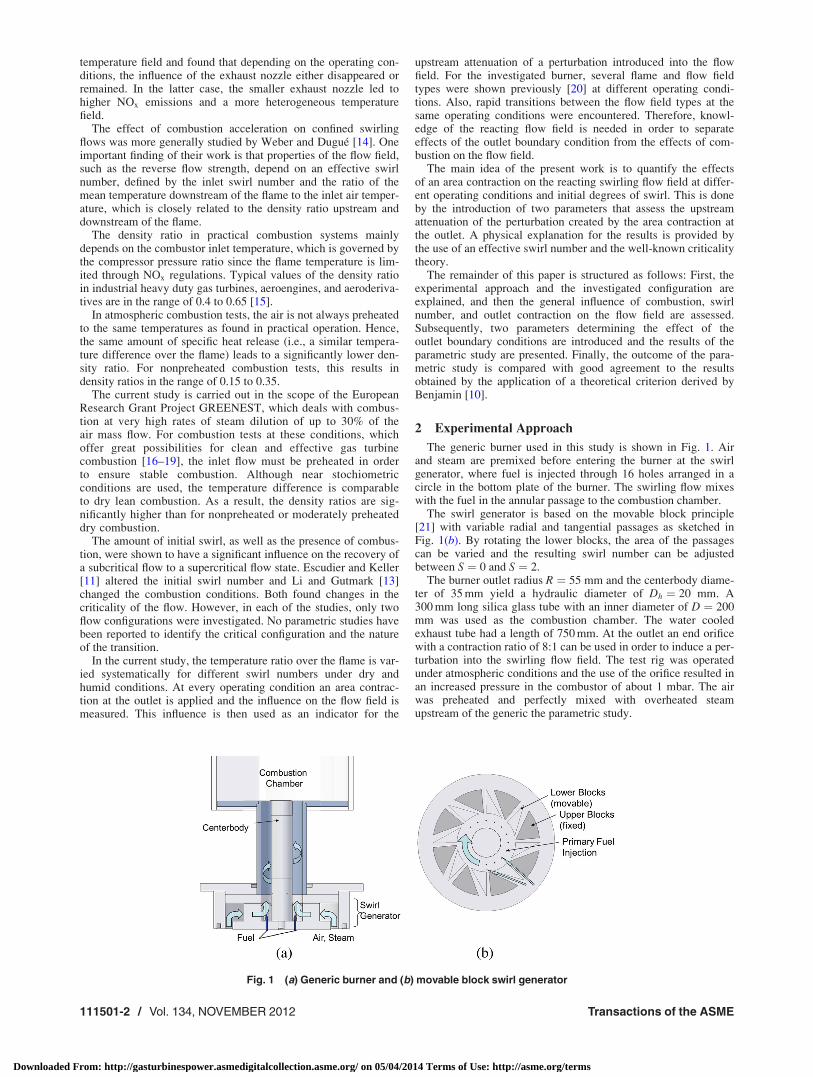
The generic burner used in this study is shown in Fig. 1. Airand steam are premixed before entering the burner at the swirlgenerator, where fuel is injected through 16 holes arranged in acircle in the bottom plate of the burner. The swirling flow mixeswith the fuel in the annular passage to the combustion chamber.
The swirl generator is based on the movable block principle[21] with variable radial and tangential passages as sketched inFig. 1(b). By rotating the lower blocks, the area of the passagescan be varied and the resulting swirl number can be adjustedbetween S ¼ 0 and S ¼ 2.
The burner outlet radius R ¼ 55 mm and the centerbody diame-ter of 35 mm yield a hydraulic diameter of Dh ¼ 20 mm. A300 mm long silica glass tube with an inner diameter of D ¼ 200mm was used as the combustion chamber. The water cooledexhaust tube had a length of 750 mm. At the outlet an end orificewith a contraction ratio of 8:1 can be used in order to induce a per-turbation into the swirling flow field. The test rig was operatedunder atmospheric conditions and the use of the orifice resulted inan increased pressure in the combustor of about 1 mbar. The airwas preheated and perfectly mixed with overheated steamupstream of the generic the parametric study.
Fig. 1 (a) Generic burner and (b) movable block swirl generator
111501-2 / Vol. 134, NOVEMBER 2012 Transactions of the ASME
Downloaded From: http://gasturbinespower.asmedigitalcollection.asme.org/ on 05/04/2014 Terms of Use: http://asme.org/terms
The steam content X is defined as the ratio of the mass flowrate of steam _msteam to the mass flow rate of air _mair:
X ¼ _msteam
_mair
(1)
While the steam content was varied between X ¼ 0 and 0.3, thetotal mass flow was kept constant for all measurements at_mair þ _msteam¼ 180 kg/h.
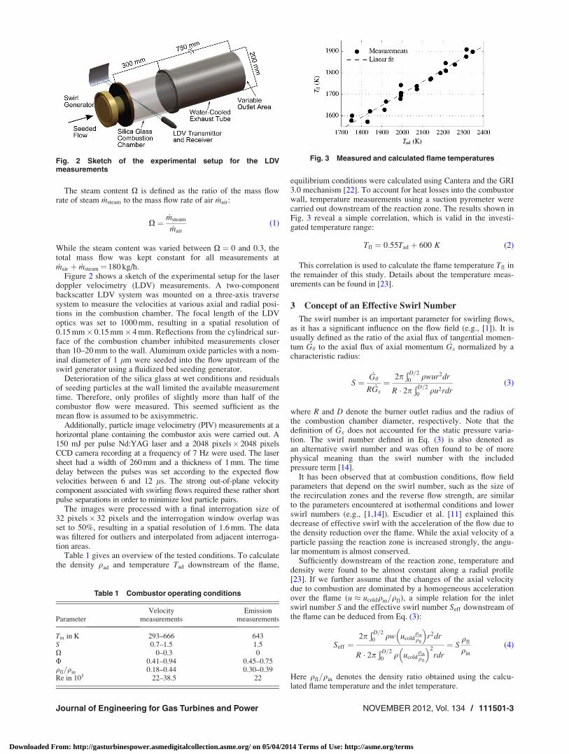
Figure 2 shows a sketch of the experimental setup for the laserdoppler velocimetry (LDV) measurements. A two-componentbackscatter LDV system was mounted on a three-axis traversesystem to measure the velocities at various axial and radial posi-tions in the combustion chamber. The focal length of the LDVoptics was set to 1000 mm, resulting in a spatial resolution of0.15 mm� 0.15 mm� 4 mm. Reflections from the cylindrical sur-face of the combustion chamber inhibited measurements closerthan 10–20 mm to the wall. Aluminum oxide particles with a nom-inal diameter of 1 lm were seeded into the flow upstream of theswirl generator using a fluidized bed seeding generator.
Deterioration of the silica glass at wet conditions and residualsof seeding particles at the wall limited the available measurementtime. Therefore, only profiles of slightly more than half of thecombustor flow were measured. This seemed sufficient as themean flow is assumed to be axisymmetric.
Additionally, particle image velocimetry (PIV) measurements at ahorizontal plane containing the combustor axis were carried out. A150 mJ per pulse Nd:YAG laser and a 2048 pixels� 2048 pixelsCCD camera recording at a frequency of 7 Hz were used. The lasersheet had a width of 260 mm and a thickness of 1 mm. The timedelay between the pulses was set according to the expected flowvelocities between 6 and 12 ls. The strong out-of-plane velocitycomponent associated with swirling flows required these rather shortpulse separations in order to minimize lost particle pairs.
The images were processed with a final interrogation size of32 pixels� 32 pixels and the interrogation window overlap wasset to 50%, resulting in a spatial resolution of 1.6 mm. The datawas filtered for outliers and interpolated from adjacent interroga-tion areas.
Table 1 gives an overview of the tested conditions. To calculatethe density qad and temperature Tad downstream of the flame,
equilibrium conditions were calculated using Cantera and the GRI3.0 mechanism [22]. To account for heat losses into the combustorwall, temperature measurements using a suction pyrometer werecarried out downstream of the reaction zone. The results shown inFig. 3 reveal a simple correlation, which is valid in the investi-gated temperature range:
Tfl ¼ 0:55Tad þ 600 K (2)
This correlation is used to calculate the flame temperature Tfl inthe remainder of this study. Details about the temperature meas-urements can be found in [23].
3 Concept of an Effective Swirl Number
The swirl number is an important parameter for swirling flows,as it has a significant influence on the flow field (e.g., [1]). It isusually defined as the ratio of the axial flux of tangential momen-tum _Gh to the axial flux of axial momentum _Gx normalized by acharacteristic radius:
S ¼_Gh
R _Gx
¼2pÐD=2
0qwur2dr
R � 2pÐD=2
0qu2rdr
(3)
where R and D denote the burner outlet radius and the radius ofthe combustion chamber diameter, respectively. Note that thedefinition of _Gx does not accounted for the static pressure varia-tion. The swirl number defined in Eq. (3) is also denoted asan alternative swirl number and was often found to be of morephysical meaning than the swirl number with the includedpressure term [14].
It has been observed that at combustion conditions, flow fieldparameters that depend on the swirl number, such as the size ofthe recirculation zones and the reverse flow strength, are similarto the parameters encountered at isothermal conditions and lowerswirl numbers (e.g., [1,14]). Escudier et al. [11] explained thisdecrease of effective swirl with the acceleration of the flow due tothe density reduction over the flame. While the axial velocity of aparticle passing the reaction zone is increased strongly, the angu-lar momentum is almost conserved.
Sufficiently downstream of the reaction zone, temperature anddensity were found to be almost constant along a radial profile[23]. If we further assume that the changes of the axial velocitydue to combustion are dominated by a homogeneous accelerationover the flame (u � ucoldqin=qfl), a simple relation for the inletswirl number S and the effective swirl number Seff downstream ofthe flame can be deduced from Eq. (3):
Seff ¼2pÐD=2
0qw ucold
qin
qfl
� �r2dr
R � 2pÐD=2
0q ucold
qin
qfl
� �2
rdr¼ S
qfl
qin
(4)
Here qfl=qin denotes the density ratio obtained using the calcu-lated flame temperature and the inlet temperature.
Fig. 2 Sketch of the experimental setup for the LDVmeasurements
Table 1 Combustor operating conditions
Velocity EmissionParameter measurements measurements
Tin in K 293–666 643S 0.7–1.5 1.5X 0–0.3 0U 0.41–0.94 0.45–0.75qfl=qin 0.18–0.44 0.30–0.39Re in 103 22–38.5 22
Fig. 3 Measured and calculated flame temperatures
Journal of Engineering for Gas Turbines and Power NOVEMBER 2012, Vol. 134 / 111501-3
Downloaded From: http://gasturbinespower.asmedigitalcollection.asme.org/ on 05/04/2014 Terms of Use: http://asme.org/terms

Note that the effective swirl number Seff used in this study isbased on a theoretical swirl number S at the burner outlet [21].When transferring it to other burners, the specific geometries, inparticular the burner expansion ratio, must be accounted for.
The effective swirl number is shown in the presented work tobe the dominating parameter for the susceptibility of the flow fieldto downstream perturbations.
4 Results
4.1 Isothermal Flow Field. Figure 4 shows the measuredflow field in the combustor at isothermal conditions without anarea contraction at the outlet. The typical features of the flow fieldin a swirl-stabilized combustor can be observed: An annular jetemanating from the mixing tube, an internal recirculation zone(IRZ) generated by vortex breakdown, and an outer recirculationzone (ORZ) induced by the area change and the confinement. Thevelocity vectors are superimposed on the two-dimensional turbu-lence intensity I normalized with the burner outlet velocity u0:
I ¼ 1
u0
ffiffiffiffiffiffiffiffiffiffiffiffiffiffiffiffiffiffiffiffiffiffiffiffiffiffiffiffiffiffiffiffi0:5 u02rms þ v02rms
� �q(5)
Axial and tangential velocity profiles from LDV measurementsof the isothermal flow field are shown in Fig. 5. The axial veloc-ities at the upstream location show the previously mentionedzones of the emanating jet, the IRZ, and the ORZ. At the down-
stream location no ORZ is present and the IRZ is significantlywider with lower recirculating velocities. The tangential profilesshow a shape similar to a solid body vortex core surrounded by afree-vortex.
The general effects of the area contraction on the isothermalflow field are shown in Figs. 4(b) and 5. Even at the lowest meas-ured swirl number (S ¼ 0:7), significant changes can be observed.In a region near the center line, the direction of axial velocitychanges from a homogeneous backflow to a flow in the forwarddirection. This leads to a change in the shape of the IRZ from aspherical to a V-shaped form. In the radial profiles measured atthe downstream position (x=Dh ¼ 10), in addition to the effects onthe axial velocity near the center line, it can be observed that themaximum tangential velocity is considerably higher and the peakshifts inward.
These changes come along with a significant increase in theturbulence level near the center line. The velocity fluctuations areaugmented in all three components but are particularly increased inthe radial and tangential component. Hence, the two-dimensionalturbulence intensity shown in Fig. 4 somewhat underestimates theincrease in turbulence intensity caused by the outlet contraction.
The higher turbulence near the center line is believed to stemfrom the steeper gradient of the tangential velocity near the vortexcenter. Periodical and random movement of the core leads tohigher fluctuation both in the measured radial and tangentialvelocities [24].
A similar general behavior has been described in literature[11,13,24]. For higher swirl numbers the mentioned effects becomemore pronounced and extend further upstream.
4.2 Reacting Flow Field. Independently of the outlet bound-ary conditions, combustion can lead to very different flow fieldsin the combustor used. Before assessing the influence of an outletcontraction on the flow field, it is, therefore, necessary to brieflycharacterize the observed flow fields in order to separate effects ofcombustion from the effects of the outlet area contraction.
Two significantly different reacting flow fields can be seen inFig. 6 for a swirl number of S ¼ 0:7 at two combustor operatingconditions. The flame of Fig. 6, which anchors near the burneroutlet, leads to strong changes in the flow field compared to theisothermal flow field. The opening angle of the emanating jet isconsiderably higher and leads to a wider IRZ near the burner
Fig. 4 Isothermal flow field at S ¼ 0:7 measured with PIV.Velocity vectors superimposed on the normalized turbulenceintensity. Solid lines are the isocontours of zero axial velocity.Dashed lines show measurement locations of LDVmeasurements.
Fig. 5 Radial velocity profiles at isothermal conditions(S ¼ 0:7) with and without area contraction. Measured with LDV.
111501-4 / Vol. 134, NOVEMBER 2012 Transactions of the ASME
Downloaded From: http://gasturbinespower.asmedigitalcollection.asme.org/ on 05/04/2014 Terms of Use: http://asme.org/terms

outlet. Furthermore, in the IRZ the velocity profile is extremelyuniform (see Fig. 6) and the corresponding levels of turbulenceare very low. This flow field type will be denoted as type 1 in theremainder of the paper.
The flow fields encountered for high rates of steam dilution(Fig. 6(b)) or very lean flames, anchoring further downstream,remain very similar to the isothermal flow field. Only gradualchanges like the acceleration of the axial velocities due to thelower density downstream of the flame and a slightly smaller IRZcan be observed. The shape of the flow field will be named type 2in the following.
The different flow field types can be also observed in radial veloc-ity profiles shown in Fig. 7 for a very lean operating condition atvarious swirl numbers. The higher swirl numbers S ¼ 0:9, 1:2, and1:5 show a type 1 flow field with the very uniform and significantlywider zone of negative velocities in the IRZ in contrast to the curvedprofile encountered for the type 2 flow field for S ¼ 0:7.
However, during repeated measurements for the intermediateswirl of S ¼ 0:9, both flow field types appeared. As can be seen inFig. 7, the flow fields of type 1 and type 2 are significantly differ-ent. Hence, care must be taken when the influence of the area con-traction is assessed, to avoid comparison of two flow fields ofdifferent types.
The reduction of the effective swirl intensity due to combustioncan be observed in Fig. 8. Velocity profiles for the highest swirl atthree operating conditions with different density ratios and, there-fore, different accelerations of the flow due to heat release areshown. In contrast to Fig. 7, the velocities are normalized by the
combustor outlet velocity uc (assuming the calculated flame tem-peratures) instead of the burner outlet velocity u0. All flow fieldsare of type 1 and, consequently, the normalized axial velocitiesare very similar for the different density ratios. The tangentialvelocities are almost not affected by the acceleration, hence, ahigher acceleration over the flame leads to lower normalized tan-gential velocities. This scaling can be observed very well by com-paring the profiles of Fig. 8 to the downstream profiles of Fig. 7.The profiles for the same swirl number but different density ratiosshow the same trends as the profiles for the same operating condi-tions but different swirl numbers.
4.3 Effect of Outlet Area Contraction on the ReactingFlow Field. The two reacting flow fields (S ¼ 0:7) presented inFig. 6 were both measured with an area contraction at the outlet.The flow field of the dry case (Fig. 6) with a density ratio ofqfl=qin ¼ 0:33 and an effective swirl number of Seff ¼ 0:24 showsno influence of the area contraction as observed in Fig. 4(b). Forthe humid case (Fig. 6(b), qfl=qin ¼ 0:39, Seff ¼ 0:27) only a veryslight increase in the turbulence intensity was observed at axialpositions x=Dh > 10.
Figure 9 shows the flow fields at the same operating conditionsfor a higher inlet swirl number of S ¼ 1:2 and resulting effective
Fig. 6 Reacting flow fields at S ¼ 0:7 with area contraction. (a)Flow field type 1 and (b) flow field type 2. Solid lines are the iso-contours of zero axial velocity.
Fig. 7 Radial velocity profiles for various swirl numbers atcombustion conditions (Tin ¼ 527 K; / ¼ 0:49; X ¼ 0) withoutarea contraction
Fig. 8 Radial velocity profiles (x=Dh ¼ 10) at S ¼ 1:5 withoutarea contraction at the outlet for three density ratios
Journal of Engineering for Gas Turbines and Power NOVEMBER 2012, Vol. 134 / 111501-5
Downloaded From: http://gasturbinespower.asmedigitalcollection.asme.org/ on 05/04/2014 Terms of Use: http://asme.org/terms

swirl numbers of Seff ¼ 0:41 and 0.47. The change in the shape ofthe IRZ and the increase in the turbulence intensity near the centerline can be clearly observed at both conditions, however, it ismore pronounced for the humid case. As in the isothermal case,the increase in turbulence is likely to stem mainly from the steepergradients of the tangential velocity component near the centerline.
A better insight into the influence of the outlet boundary condi-tion on the flow field can be obtained by evaluating velocity pro-files for differing outlet area contractions, as shown in Figs. 10and 11. Radial profiles of axial and tangential velocities weremeasured for a high swirl number S ¼ 1:5 at two different operat-ing conditions with high and low acceleration over the flame(qfl=qin ¼ 0:19 and 0.35, Seff ¼ 0:28 and 0.52, respectively).While the case with the high acceleration and the lower effectiveswirl number is not influenced by the area contraction, the casewith low acceleration and the higher effective swirl number is sig-nificantly influenced. The effects of higher axial velocity near thecenter line and an inwardly shifted higher peak of the tangentialvelocity resulting in a steeper gradient remain similar to the iso-thermal case.
4.4 Parametric Study. The results presented in Figs. 6 and9–11 clearly show the role of dilatation and inlet swirl number forthe susceptibility of the flow field to downstream perturbations.An application of the criticality theory indicates that the flow fieldwhich shows no influence of the outlet contraction must be of asupercritical flow state, and the flow field which shows an influ-ence of the outlet contraction must be of a subcritical flow state.
However, it can also be observed that the effect can be more orless pronounced depending on the operating conditions.
In order to quantitatively assess the effect of the outlet contrac-tion on the velocity profiles, two parameters are introduceddescribing the most noticeable effects on the axial and tangentialvelocity. The first parameter px describes the excess axial velocitynear the center line caused by the acceleration of the flow passingthrough the area restriction. The second parameter pH describesthe excess tangential velocity due to the constriction of the flowat the area contraction. Both parameters are calculated at the
Fig. 9 Reacting flow fields at S ¼ 1:2, with area contraction.Solid lines are the isocontours of zero axial velocity.
Fig. 10 Radial velocity profiles at S ¼ 1:5 for high accelerationdue to heat release
Fig. 11 Radial velocity profiles at S ¼ 1:5 for low accelerationdue to heat release
111501-6 / Vol. 134, NOVEMBER 2012 Transactions of the ASME
Downloaded From: http://gasturbinespower.asmedigitalcollection.asme.org/ on 05/04/2014 Terms of Use: http://asme.org/terms

downstream position of x=Dh ¼ 10, more than 850 mm upstreamof the area contraction. By evaluating the parameters for differentoperating conditions, the upstream attenuation of the perturbationcreated at the area contraction, which is closely related to the crit-icality of the flow, can be quantitatively assessed:
px ¼1
uc
ð0:5
�0:5
u2 � u1ð Þ � d x
Dh
� �(6)
pH ¼1
max w1ð Þ
ð1
0
w2 � w1ð Þ � d x
Dh
� �(7)
The subscripts 1 and 2 denote the undisturbed flow and the flowwith area contraction, respectively. The parameters are normal-ized by the combustor outlet velocity uc and the maximum swirlvelocity of the undisturbed flow, respectively.
It was observed during the measurements that for flow fieldsshowing a large influence of the area contraction ratio, the centerof the vortex is slightly shifted from the center line. This asymme-try, which can be also observed in Fig. 4(b), was reported previ-ously by Escudier et al. [24]. To account for this when calculatingpH, the profile w2 is shifted so that w2 x=Dh ¼ 0ð Þ � 0.
The influence of the inlet swirl number and the density ratio onthe parameters px and pH is shown in Fig. 12. The expected trendscan be observed: Higher initial swirl numbers and higher densityratios (i.e., lower temperature ratios) lead to weaker attenuation ofthe downstream perturbation and, thus, higher values of px andpH. For inlet swirl numbers of S ¼ 0:7 and S ¼ 1:5, sufficient dataare available to find that starting from a critical density ratio, theparameters increase almost linearly. The critical density ratio,however, depends on the amount of initial swirl.
It is worth noting that Fig. 12 and the following figures present-ing the parameters px and pH include dry measurements (X ¼ 0)as well as highly steam diluted measurements (X ¼ 0:3).
The concept of the effective swirl number can be used to com-pare different inlet swirl numbers and different operating condi-tions. In Fig. 13 the parameters px and pH are shown as a functionof the effective swirl number. It can be observed that the parame-ters match quite well for the different inlet swirl numbers. A linearregression of the parameter px that also fits reasonably well theisothermal measurements (not shown here) reveals the range ofthe critical effective swirl number (Seff ¼ 0:2 to 0.3) at which theperturbation caused by the area contraction is fully attenuated atthe measurement location. This critical effective swirl number isslightly lower for the low swirl case of S ¼ 0:7 than for S ¼ 1:5.This is likely to stem from the different flow field types foundat critical conditions for S ¼ 0:7 (type 2 flow field) and S ¼ 1:5(type 1 flow field).
In addition to the flow field measurements, an emission analysiswas carried out for the operating conditions shown in Table 1.The results, presented in Fig. 14, reveal that the NOx emissionsare not influenced significantly by the area contraction, eventhough the flow was clearly of a subcritical state(Seff ¼0.45–0.58).
5 Discussion
The results clearly show that the upstream attenuation of a per-turbation introduced at the outlet boundary condition depends onthe effective swirl number after the flame. According to theresults, a critical effective swirl number of Seff ¼ 0:2 to Seff ¼ 0:3can be deduced. The flow field of type 2 seemed slightly morealtered by the area contraction at the same effective swirl number.
The overall trend is in accordance to the criticality theory bySquire [9] and Benjamin [10] and the interpretation of Escudierand Keller [11], in a way that higher axial velocities lead to super-critical flow states and higher tangential velocities lead to subcriti-cal flow states where an upstream transport of perturbations ispossible.
Both Squire and Benjamin developed criteria in order to testvelocity profiles for their criticality. Squire provides “rules ofthumb” to compare the maximum tangential velocity to a constantaxial velocity for three different vortex types. Li and Gutmark[13] applied these rules replacing the constant axial velocity bythe maximum axial velocity.
Leschziner and Hogg [25] used a criterion based on Benjamin’swork for an inviscid Rankine vortex to obtain the critical solidbody rotational speed xc for a given mean axial velocity uc, com-bustion chamber diameter D, and vortex radius ra:
J0 2xcra
uc
� �
J1 2xcra
uc
� � ¼ � rauc
xcD2
� �2�r2a
h i (8)
where J0 and J1 denote Bessel functions of the first kind.
Fig. 12 Influence of the density ratio on the parameters px andpH at different swirl numbers and combustor operatingconditions
Fig. 13 Influence of the effective swirl number on the parame-ters px and pH at different swirl numbers and combustor operat-ing conditions
Fig. 14 NOx emissions for premixed flame at subcritical condi-tons (Seff ¼0.45–0.58)
Journal of Engineering for Gas Turbines and Power NOVEMBER 2012, Vol. 134 / 111501-7
Downloaded From: http://gasturbinespower.asmedigitalcollection.asme.org/ on 05/04/2014 Terms of Use: http://asme.org/terms

A solid body vortex with a rotational speed faster than the criti-cal rotational speed xc is considered to be subcritical and a slowerrotating vortex is considered to be supercritical.
This criterion was applied to the measured velocities. As theassumption of a solid body vortex core is reasonably in line withthe measured tangential velocity profiles at the downstream posi-tion (x=Dh ¼ 10Þ, the vortex radius ra and the actual solid bodyrotational speed xm can be estimated with fair accuracy from thevelocity data.
Hence, for every operating condition, a critical solid body rota-tional speed xc can be obtained. The ratio of the estimated rota-tional speed to the critical solid body rotational speed can beintroduced as the criticality factor j:
j ¼ xm
xc(9)
Figure 15 shows the criticality factor j as a function of the effec-tive swirl number Seff . It can be observed that j is close to unityfor effective swirl numbers in the range of Seff ¼ 0:2 to Seff ¼ 0:3.For very low effective swirl numbers, the supercritical state canbe observed with values of j smaller than unity. This matches thecritical swirl number estimated from a linear regression of the pa-rameters px and pH very well. Furthermore, it can be observedagain that minor differences between the two flow field types ofthe low swirl number S ¼ 0:7 and the high swirl number S ¼ 1:5exist.
The good correlation between the parameters px and pH and thecriticality parameter j can be observed in Fig. 16. For values ofj < 1, both px and pH remain constant near zero. Starting fromj ¼ 1, both parameters then grow almost linearly with j. As j
already accounts for the changes in the flow field shape, no sys-tematic differences between the low swirl number S ¼ 0:7 and thehigh swirl number S ¼ 1:5 can be observed.
Since j can be calculated from single radial velocity profiles af-ter the flame by application of Eq. (9), it can be used to predictwhether or not the flow is subcritical and allows for the estimationof the influence of the outlet boundary condition on the flow field.
According to the criticality theory, the flow field is basically in-dependent of the outlet boundary conditions if in the flow fieldbetween the measurement position (downstream of the flame) andthe outlet the flow recovers to a supercritical state at least once.Usually this can be achieved due to viscous swirl attenuation andboundary layer growth. Under combustion conditions, heat loss tothe exhaust tube must be further considered. Since the exhausttube in the presented experiments is water cooled, it is assumedthat the heat loss effect increases the swirl number stronger thanthe weakening of the swirl due to viscous effects. Hence, the mostsupercritical position is assumed to be directly downstream or inthe vicinity of the flame. This assumption seems to be valid sinceFig. 16 shows a very good dependence of the parameters px andpH on the effective swirl number Seff (calculated with the flametemperature) and also on the criticality parameter j. Even at sub-critical conditions, an area contraction at the outlet had no signifi-cant influence on the measured NOx emissions. This implies thatfrom emission measurements of premixed flames only limitedconclusions about the flow state can be drawn.
6 Conclusions
Velocity measurements have been carried out in a swirl stabi-lized combustor for various swirl numbers and operating condi-tions including very high rates of steam dilution. All measurementswere conducted with an open outlet and an area contraction of 8:1.The qualitative effects on the velocity profiles, the shape of theIRZ, and the turbulence distribution are the same as described byother authors. To quantitatively assess the upstream attenuation ofthe perturbation created at the outlet boundary condition, two pa-rameters concerning the axial and tangential velocity distribution,respectively, were introduced.
To compare different inlet swirl numbers and combustor operat-ing conditions, the concept of an effective swirl number was usedand validated for the measured configurations. It was found thatthe susceptibility of the flow field to downstream perturbationsmostly depends on this effective swirl number. When the effectiveswirl number was larger than a critical value of Seff ¼ 0:2 toSeff ¼ 0:3, the parameters started to increase linearly. This linearbehavior is valid for dry as well as for steam diluted conditions.
A criticality criterion was applied to assess the criticality of thevelocity profiles measured at the downstream position. The resultsof the analysis yield a critical effective swirl number of Seff ¼ 0:2to Seff ¼ 0:3, which matched very well with the results obtainedfrom the parametric study.
For moderately preheated laboratory flames with low swirl num-bers (that still ensure vortex breakdown), the outlet boundary con-ditions are of minor importance for the flow field. However, forwell preheated very lean or highly diluted flames, such as steamdiluted flames, much higher effective swirl numbers are possible.
It is, therefore, of importance to be aware of the flow state andthe outlet boundary conditions when comparing measurementresults obtained on different test rigs or when changing the outletboundary conditions in order to suppress thermoacoustic instabil-ities. Furthermore, it is known that the quality of numerical simu-lations depends significantly on the validity of the boundaryconditions. However, the application of adequate subcritical outletboundary conditions is still challenging [24,25] and due to limita-tions of the domain size, it is often impractical to simulate theentire flow field up to a state where the flow eventually recoversto a supercritical flow state.
No significant influence of an area contraction on the NOx
emissions was found for technically premixed flames.
Fig. 15 Criticality parameter j for different effective swirl num-bers. Dashed line divides subcritical from supercritical flow.
Fig. 16 Influence of the criticality parameter j on the parame-ters px and pH
111501-8 / Vol. 134, NOVEMBER 2012 Transactions of the ASME
Downloaded From: http://gasturbinespower.asmedigitalcollection.asme.org/ on 05/04/2014 Terms of Use: http://asme.org/terms

If the swirl number is defined adequately and the burner geome-try, in particular the burner expansion ratio, is taken into account,the usage of the effective swirl number, which is defined by theinlet swirl number and the operating conditions, allows for an esti-mation of whether the outlet boundary conditions have a signifi-cant effect on the flow field or may be neglected.
Acknowledgment
The research leading to these results has received funding fromthe European Research Council under the ERC grant agreement247322, GREENEST. The authors would like to thank AndyGohrs, Eduard Hoschele and the CONFET for assistance in thelab and helpful discussions.
Nomenclature
D ¼ combustion chamber diameter (m)Dh ¼ hydraulic diameter of the burner outlet (m)_Gh ¼ axial flux of angular momentum (N m)_Gx ¼ axial flux of axial momentum (N)I ¼ normalized turbulence intensityJ ¼ Bessel function of the first kindR ¼ burner outlet radius (m)
Re ¼ Reynolds number based on the hydraulic diameter Dh
S ¼ inlet swirl numberSeff ¼ effective swirl numberTin ¼ inlet temperature (K)Tad ¼ calculated adiabatic flame temperature of the mixture
(K)Tfl ¼ calculated flame temperature (K)
_m ¼ mass flow (kg/h)px; pH ¼ parameters defining the outlet influence on the axial and
tangential velocity profilesr ¼ radial position (m)
ra ¼ radius of the solid body vortex (m)u ¼ mean axial velocity (m/s)
u0 ¼ bulk velocity at burner outlet (m/s)uc ¼ bulk velocity at combustor outlet assuming the
calculated flame temperature (m/s)v ¼ mean radial velocity (m/s)w ¼ mean tangential velocity (m/s)x ¼ axial position (m)X ¼ degree of humidityU ¼ equivalence ratioj ¼ criticality parameter
qin ¼ inlet density (kg/m3)qfl ¼ density downstream the flame (kg/m3)x ¼ rotational speed of the solid body vortex core (rad/s)
References[1] Syred, N., and Beer, J. M., 1974, “Combustion in Swirling Flows: A Review,”
Combust. Flame, 23(2), pp. 143–201.[2] Huang, Y., and Yang, V., 2009, “Dynamics and Stability of Lean-Premixed
Swirl-Stabilzed Combustion,” Progress Energy Combust. Sci., 35(4),pp. 293–364.
[3] Lieuwen, T., and Yang, V., 2005, Combustion Instabilities in Gas TurbineEngines: Operational Experience, Fundamental Mechanisms, and Modeling(Progress in Astronautics and Aeronautics), Vol. 210, American Institute ofAeronautics and Astronautics, Reston, VA.
[4] Zajadatz, M., Lachner, R., Bernero, S., Motz, C., and Flohr, P., 2007,“Development and Design of Alstoms’s Staged Fuel Gas Injection EV Burnerfor NOx Reduction,” Proceedings of GT2007 ASME Turbo Expo 2007: Powerfor Land, Sea and Air, Montreal, Canada, May 14–17, ASME Paper No.GT2007-27730.
[5] Schuermans, B., Guthe, F., Pennell, D., Guyot, D., and Paschereit, C. O., 2010,“Thermoacoustic Modeling of a Gas Turbine Using Transfer Functions Meas-ured Under Full Engine Pressure,” ASME J. Eng. Gas Turbines Power,132(11), p. 111503.
[6] Kim, K. T., Lee, J. G., Quay, B. D., and Santavicca, D. A., 2010, “SpatiallyDistributed Flame Transfer Functions for Predicting Combustion Dynamics inLean Premixed Gas Turbine Combustors,” Combust. Flame, 157(9), pp.1718–1730.
[7] Mongia, H. C., Held, T. J., and Hsiao, G. C., 2003, “Challenges and Progress inControlling Dynamics in Gas Turbine Combustors,” J. Propul. Power, 19(5),pp. 822–829.
[8] �Cosic, B., Bobusch, B. C., Moeck, J. P., and Paschereit, C. O., 2012, “Open-Loop Control of Combustion Instabilities and the Role of the Flame Responseto Two-Frequency Forcing,” ASME J. Eng. Gas Turbines Power, 134(6),p. 061502.
[9] Squire, H. B., 1962, “Analysis of the Vortex Breakdown Phenomenon. Part I,”Miszellaneen der Angewandten Mechanik, Akademie, Berlin, pp. 306–312.
[10] Benjamin, T. B., 1962, “Theory of the Vortex Breakdown Phenomenon,” J.Fluid Mech., 14(04), pp. 593–629.
[11] Escudier, M. P., and Keller, J. J., 1985, “Recirculation in Swirling Flow—AManifestation of Vortex Breakdown,” AIAA J., 23(1), pp. 111–116.
[12] Altgeld, H., Jones, W. P., and Wilhelmi, J., 1983, “Velocity Measurements in aConfined Swirl Driven Recirculating Flow,” Exp. Fluids, 1(2), pp. 73–78.
[13] Li, G., and Gutmark, E. J., 2005, “Effect of Exhaust Nozzle Geometry onCombustor Flow Field and Combustion Characteristics,” Proc. Combust. Inst.,30(2), pp. 2893–2901.
[14] Weber, R., and Dugue, J., 1992, “Combustion Accelerated Swirling Flows inHigh Confinements,” Progress Energy Combust. Sci., 18(4), pp. 349–367.
[15] Soares, C., 2007, Gas Turbines: A Handbook of Air, Land and Sea Applications.Butterworth Heinemann, London.
[16] Bartlett, M. A., and Westermark, M. O., 2005, “A Study of Humidified GasTurbines for Short-Term Realization in Midsized Power Generation—Part I:Nonintercooled Cycle Analysis,” ASME J. Eng. Gas Turbines Power, 127(1),pp. 91–99.
[17] Bartlett, M. A., and Westermark, M. O., 2005, “A Study of Humidified GasTurbines for Short-Term Realization in Midsized Power Generation—Part II:Intercooled Cycle Analysis and Final Economic Evaluation,” ASME J. Eng.Gas Turbines Power, 127(1), pp. 100–108.
[18] Goke, S., Gockeler, K., Kruger, O., and Paschereit, C. O., 2010,“Computational and Experimental Study of Premixed Combustion at Ultra WetConditions,” Proceedings of GT2010 ASME Turbo Expo 2010: Powerfor Land, Sea and Air, Glasgow, Scotland, June 14–18, ASME Paper No.GT2010-23417.
[19] Goke, S., Terhaar, S., Schimek, S., Gockeler, K., and Paschereit, C. O.,2011, “Combustion of Natural Gas, Hydrogen and Bio-Fuels at Ultra-Wet Conditions,” Proceedings of ASME Turbo Expo 2011: Power for Land,Sea and Air, Vancouver, Canada, June 6–10, ASME Paper No. GT2011-45696.
[20] Terhaar, S., Gockeler, K., Schimek, S., Goke, S., and Paschereit, C. O., 2011,“Non-Reacting and Reacting Flow in a Swirl-Stabilized Burner for Ultra-WetCombustion,” Proceedings of 41st AIAA Fluid Dynamics Conference andExhibit, Honolulu, HI, June 27–30, AIAA Paper No. 2011-3584.
[21] Leuckel, W., 1967, “Swirl Intensities, Swirl Types and Energy Losses of Differ-ent Swirl Generating Devices,” IFRF Doc. Nr. G, 2(0).
[22] Smith, G. P., Golden, D. M., Frenklach, M., Moriarty, N. W., Eiteneer, B.,Goldenberg, M., Bowman, C. T., Hanson, R. K., Song, S., Gardiner, W. C., Lis-sianski, V. V., and Qin, Z., “GRI-Mech 3.0,” http://www.me.berkeley.edu/gri_-mech/, accessed February 2, 2012.
[23] Goke, S., and Paschereit, C. O., 2012, “Influence of Steam Dilution onNOx Formation in Premixed Natural Gas and Hydrogen Flames,” 50thAIAA Aerospace Science Meeting, AIAA-2012-1272, Nashville, TN, January9–12.
[24] Escudier, M. P., Nickson, A. K., and Poole, R. J., 2006, “Influence of Outlet Ge-ometry on Strongly Swirling Turbulent Flow Through a Circular Tube,” Phys.Fluids, 18(12), p. 125103.
[25] Leschziner, M. A., and Hogg, S., 1989, “Computation of Highly SwirlingConfined Flow With a Reynolds Stress Turbulence Model,” AIAA J., 27(1),pp. 57–63.
Journal of Engineering for Gas Turbines and Power NOVEMBER 2012, Vol. 134 / 111501-9
Downloaded From: http://gasturbinespower.asmedigitalcollection.asme.org/ on 05/04/2014 Terms of Use: http://asme.org/terms