Effects of Noise in Time Dependent RWM Feedback … · O. Katsuro-Hopkins, J. Bialek, G. Navratil...
28
Effects of Noise in Time Dependent RWM Feedback Simulations O. Katsuro-Hopkins, J. Bialek, G. Navratil (Department of Applied Physics and Applied Mathematics, Columbia University, New York, NY USA) Building on the successful experiments on HBT-EP and DIII-D, active feedback control of the resistive wall mode (RWM) has emerged as an essential part of present and planned tokamak designs. In an effort to advance our feedback model closer to actual experimental conditions, the VALEN code was modified by introducing noise into the closed loop control system. In practice, feedback system performance is limited by detection thresholds and the stable operating range that is set by both systematic error and random noise in the measurement input to the feedback control loop. The results of an initial survey analyzing the effects of systematic error and noise (white, Gaussian, 1/f, etc.) on the RWM feedback system performance is performed using the newly developed time dependent capability in VALEN (see poster by J. Bialek).
Transcript of Effects of Noise in Time Dependent RWM Feedback … · O. Katsuro-Hopkins, J. Bialek, G. Navratil...

Effects of Noise in Time Dependent RWM Feedback Simulations
O. Katsuro-Hopkins, J. Bialek, G. Navratil
(Department of Applied Physics and Applied Mathematics, ColumbiaUniversity, New York, NY USA)
Building on the successful experiments on HBT-EP and DIII-D, activefeedback control of the resistive wall mode (RWM) has emerged as anessential part of present and planned tokamak designs. In an effort to advanceour feedback model closer to actual experimental conditions, the VALENcode was modified by introducing noise into the closed loop control system.In practice, feedback system performance is limited by detection thresholdsand the stable operating range that is set by both systematic error and randomnoise in the measurement input to the feedback control loop. The results of aninitial survey analyzing the effects of systematic error and noise (white,Gaussian, 1/f, etc.) on the RWM feedback system performance is performedusing the newly developed time dependent capability in VALEN (see posterby J. Bialek).

Motivations
• Control of long-wavelength MHD instabilities using conducting walls
and external magnetic perturbations is a very promising route to
improved reliability and better performance of magnetic confinement
fusion devices.
• It is well known that control of these resistive wall slowed kink modes
above the no-wall beta limit is essential to achieve bootstrap current
sustained steady-state operation in a high gain tokamak fusion energy
systems.
• The ability to accurately model and predict the performance of active
MHD control systems is critical to present and future advanced
confinement scenarios and machine design studies. The VALEN
modeling code has been designed and bench marked to predict the
performance limits of MHD control systems.

• To enhance VALEN’s ability to model more realistic feedback
systems initial value, time dependent capability was added to the code.
• To advance our feedback model closer to actual experimental
conditions, the VALEN code was also modified by introducing noise
into the closed loop control system.
• Understanding of non-ideal effects in feedback loop including
systematic error and noise (white, Gaussian, 1/f, etc.) on the RWM
feedback system performance is important for improved performance
of tokamaks.

VALEN: A Reliable Computational Tool For RWM Passive and Active Control System Study
•VALEN is the only code available to model 3D external conducting structures withreal porthole penetrations and other complex geometric features. Modeling of these
features is crucial for accurately determining the passive stabilization properties of current and future devices
•VALEN models unstable plasma modes using an electrical circuit representationdeveloped by Boozer and plasma mode structure from DCON
•VALEN models arbitrary external conducting structures using a 3D finite element electromagnetic formulation developed by Bialek
•VALEN models arbitrary sensors, control coils and the control loop feedback logicthat connects them to determine the effectiveness of feedback systems•VALEN predicts the growth rate of the instability, feedback currents and controlsystem gain, and current distributions in the external passive structure to characterizeRWM feedback performance•VALEN models initial value, time dependent problem•VALEN models non-ideal effects in feedback loop including systematic error andnoise

The VALEN Equations
The VALEN matrix equations describing the conducting structure and modeand control coil geometry are for the unknowns {Iw}, {Id}, and {Ip} are:
Lww� � I w� �� Mwp� � I d
� �� Mwp� � I p� �� �w� � flux @ wall
flux @ plasma
stability equation
Mpw� � I w� �� Lp� � I d
� �� Lp� � I p� �� �� �
Lp� � I p� �� S� � �� �
��w� �� Rww� � Iw
� �� V� �
��� �� Rd� � I d
� �� 0� �
The equivalent circuit (induction) equationsdescribing the system mode growth are then:
Msw� � Msd� � Msp� �� �
I w� �
I d� �
I p� �
��
��
��
��
��
��
��
��
��
��
s� �
Where {V} depends on sensor signals {�s} via thefeedback loop equations:

• VALEN uses DCON ( A. Glasser ) results without a conducting wallto formulate the stability equation
• Energy change �W = �����i�i2 in plasma & surroundings has
negative eigenvalues �i if an instability exists, fi(�,�) diagonalizes �Wand defines the flux from the plasma instability
• Complex helical magnetic geometry is expressed in terms ofinductance and current Li = �i / Ii and the stability equation may beexpressed as Sij=(�ij+si�ij) where si = -�iLi and the �ij may be derived
from the fi(�,�)
�
� i � fi(� ,� )���
B � d��
a�

VALEN Models External MHD Modes As SurfaceCurrents
• The interaction of an external MHD plasma instability with surrounding conductorsand coils is completely described by giving �Bnormal at the surface of theunperturbed plasma.
• VALEN uses this information in a circuit formulation of unstable plasma modes developed by Boozer to generate a finite element surface current representation of the unstable mode.
543210-0.1
0.0
0.1
Arc Length
�Bnormal calculated by DCONfor unstable plasma mode
VALEN finite element circuit repesentation of the
unstable plasma modestructure
This methodology allows VALEN to use output plasma mode informationfrom other instability physics codes (DCON, GATO, PEST or others)

VALEN's 3D Finite Element Capability Is Important In Accurately ModelingPassive Wall Stabilization Limits and Active Feedback Performance
• Correct representation of the geometricdetails of vacuum chambers with portholes and passive stabilizing plates is required to determine RWM control limits
• VALEN calculates these effects and allowsthe design of optimized control systemswith complicated real-world machinegeometry
Eddy current pattern induced in the wall of the DIII-D tokamak due to an unstable n=1
RWM [top and side view]
Eddy current pattern induced in thecontrol coils in the DIII-D tokamak

DIII-D New Internal Control Coils are an Effective Tool for Pursuing Active and Passive Stabilizations of the RWM
• Inside vacuum vessel: faster time response for feedback control
• Closer to plasma: more efficient coupling
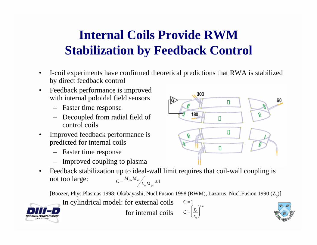
Internal Coils Provide RWM Stabilization by Feedback Control
• I-coil experiments have confirmed theoretical predictions that RWA is stabilizedby direct feedback control
• Feedback performance is improvedwith internal poloidal field sensors
– Faster time response
– Decoupled from radial field ofcontrol coils
• Improved feedback performance is predicted for internal coils
– Faster time response
– Improved coupling to plasma
• Feedback stabilization up to ideal-wall limit requires that coil-wall coupling isnot too large:
[Boozer, Phys.Plasmas 1998; Okabayashi, Nucl.Fusion 1998 (RWM), Lazarus, Nucl.Fusion 1990 (Zp)]
– In cylindrical model: for external coils
for internal coils C �
rc
rm
��
��
��
��
��
��
2mC �1
C �
Mpw MwcLw M pc
�1

RWM Noise Data on DIII-D
Q i kTi ™ d TIFF (U d) d d d t thi i t
Noise on the poloidal field sensors in the midplane. The signals are
corrected for DC offsets. The power spectral density is shown as root-mean square amplitude per 10Hz frequency bin.

Simulated RWM Noise on DIII-D w/o ELMs
Low level noise was modeled as Gaussian random number withstandard deviate 1.5 about 0 mean and frequency 10kHz

Simulated RWM Noise on DIII-D with ELMs
0.01
0.10
1.00
0.01 0.10 1.00 10.00
f(kHz)
To the low level noise ELMs (Edge Localized Modes) were addedas small group of Gaussian random numbers from 6 to 16 Gaussapproximately every 0.01 sec with different signs +/- chosen with
50% probability
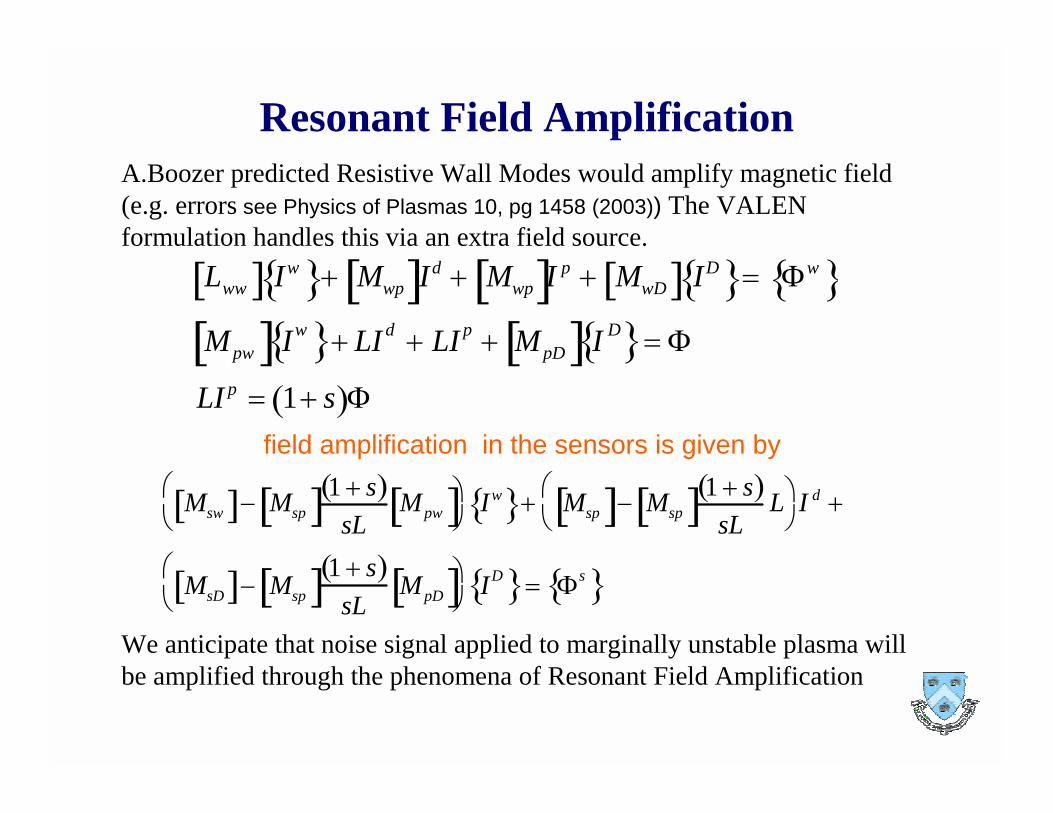
Resonant Field AmplificationA.Boozer predicted Resistive Wall Modes would amplify magnetic field(e.g. errors see Physics of Plasmas 10, pg 1458 (2003)) The VALEN formulation handles this via an extra field source.
Lww� � Iw� �� Mwp� �I
d� Mwp� �I
p� MwD� � ID
� �� �
w� �
Mpw� � Iw� �� LI d
� LI p� MpD� � I D
� �� �
LI p� 1� s� ��
field amplification in the sensors is given by
Msw� �� Msp� �1� s� �
sLMpw� �
��
��
��
��
Iw� �� Msp� �� Msp� �
1� s� �
sLL��
��
��
��
I d�
MsD� �� Msp� �1� s� �
sLMpD� �
��
��
��
��ID� ��
s� �
We anticipate that noise signal applied to marginally unstable plasma will be amplified through the phenomena of Resonant Field Amplification

Survey Feedback as Function of �normal
100
10-1
10-2
10 -1
10 0
10 1
102
10 3
104
10 5
106
g passive
g ideal
g 10^8
Data from "DIII-D.10.2003.newR&L"
s normalized mode strength
passive
ideal
I-coils
Gp=10^8 [ v/weber]
R=60.e-6 H, R = 30.e-3 ohm
10 010 -110
-1
10 0
101
102
10 3
10 4
105
10 6
g passive
g ideal
g 10^8
g 3.1623e8
g 3.9811e8
g 5.0119e8
g 6.3096e8
g 10^9
gain scan
L = 10.e-6 H, R = 200.e-3 ohm
Data from "DIII-D.10.2003.newR&L"
s normalize mode energy
passive
ideal
wall
Conversion from s to �

DIII-D I-Coil Feedback model for the Control Coils L=60 �H and R=30 mOhm
with Proportional Gain Gp=7.2Volts/Gauss
-400
-300
-200
-100
0
100
200
300
0.00 0.05 0.10 0.15 0.20 0.25
time [sec]
-1200
-1000
-800
-600
-400
-200
0
200
400
600
800
0.00 0.05 0.10 0.15 0.20 0.25
time [sec]
Control coil current

-20
-15
-10
-5
0
5
10
15
0.00 0.05 0.10 0.15 0.20 0.25
time [sec]
Sensor Flux
Voltage applied to control coil

Maximum control coil current and voltageas function of �normal

Proposed improved DIII-D I-Coil Feedback model for the Control Coils L=10 �H and R=200 mOhm with
ELMs and with Proportional Gain Gp=36 Volts/Gauss
-1300
-800
-300
200
700
1200
0.00 0.05 0.10 0.15 0.20 0.25time [sec]
-1200-1000
-800-600-400-200
0200400600800
1000
0.00 0.05 0.10 0.15 0.20 0.25
time [sec]
Control coil current

Sensor Flux
-8
-6
-4
-2
0
2
4
6
8
0.00 0.05 0.10 0.15 0.20 0.25
time [sec]
-8
-6
-4
-2
0
2
4
6
8
0.00 0.05 0.10 0.15 0.20 0.25
time [sec]
Voltage applied to control coil

Maximum control coil current and voltageas function of �normal

Proposed improved DIII-D I-Coil Feedback model for the Control Coils L=10 �H and R=200 mOhm w/o
ELMs and with Proportional Gain Gp=36 Volts/Gauss
-700
-500
-300
-100
100
300
500
700
0.00 0.05 0.10 0.15 0.20 0.25
time [sec]
-700
-500
-300
-100
100
300
500
700
0.00 0.05 0.10 0.15 0.20 0.25
time [sec]
Control coil current

Sensor Flux
Voltage applied to control coil
-7
-5
-3
-1
1
3
5
7
0.00 0.05 0.10 0.15 0.20 0.25
time [sec]
-7
-5
-3
-1
1
3
5
7
0.00 0.05 0.10 0.15 0.20 0.25
time [sec]

Maximum control coil current and voltageas function of �normal

Effects of Noise on Feedback Dynamics for L=60 �Hand R=30 mOhm DIII-D I-Coil Feedback model
with Proportional Gain Gp=7.2Volts/Gauss
Sensor Flux
-10
-5
0
5
10
15
20
25
0.000 0.002 0.004 0.006 0.008 0.010
time [sec]

0
100
200
300
400
500
600
700
800
0.000 0.002 0.004 0.006 0.008 0.010
time [sec]
-60-40-20
020406080
100120140
0.000 0.002 0.004 0.006 0.008 0.010
time [sec]
Control coil current Voltage applied to control coil

Conclusions and Future Work
• Plasma resonant RWM response to noise increases closed loop current. Ideal limit can be approached but cannot be reached.
• Noise on the sensor flux does not effect stabilization dynamic of feedback.
• Voltage for the proposed improved DIII-D I-Coil feedback model is dominated by resistance of the connection cables,lowering resistance will significantly reduce the powerrequirements.
• Future Work:– investigate effect of noise on feedback dynamic with time delay
– include noise in a full PID feedback control model
– add current and voltage limits on feedback closed loop
– add high and low frequency bandwidth limits to feedback closedloop.