A GENERAL METHOD FOR POWER FLOW ANALYSIS IN MTDC SYSTEMS.pdf
Upload
francisco-gonzalez-longattCategory
view
689download
0
www.fglongatt.org
Dr Francisco M. Gonzalez-Longatt PhD | http://fglongatt.org | Copyright © 2008-2014 1/1550th
Inte
rnat
iona
l Uni
vers
ities
Pow
er E
ngin
eerin
g C
onfe
renc
e (U
PE
C20
15)S
epte
mbe
r
1st -
4th,
201
5 | S
taffo
rdsh
ire U
nive
rsity
, UK
All
right
s re
serv
ed. N
o pa
rt o
f thi
s pu
blic
atio
n m
ay b
e re
prod
uced
or
dist
ribut
ed in
any
form
with
out
perm
issi
on o
f the
aut
hor.
Cop
yrig
ht ©
200
8-20
15. h
ttp:w
ww
.fglo
ngat
t.org
Dr Francisco M. Gonzalez-Longatt*
Prof. M.A.M.M. van der Meijden
Dr Jose Luis Rueda
www.fglongatt.org
Dr Francisco M. Gonzalez-Longatt PhD | http://fglongatt.org | Copyright © 2008-2014 2/1550th
Inte
rnat
iona
l Uni
vers
ities
Pow
er E
ngin
eerin
g C
onfe
renc
e (U
PE
C20
15)S
epte
mbe
r
1st -
4th,
201
5 | S
taffo
rdsh
ire U
nive
rsity
, UK
All
right
s re
serv
ed. N
o pa
rt o
f thi
s pu
blic
atio
n m
ay b
e re
prod
uced
or
dist
ribut
ed in
any
form
with
out
perm
issi
on o
f the
aut
hor.
Cop
yrig
ht ©
200
8-20
15. h
ttp:w
ww
.fglo
ngat
t.org
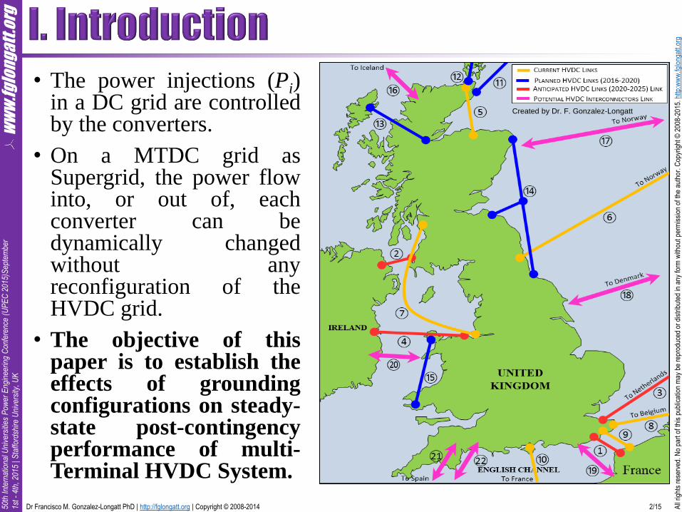
• The power injections (Pi)in a DC grid are controlledby the converters.
• On a MTDC grid asSupergrid, the power flowinto, or out of, eachconverter can bedynamically changedwithout anyreconfiguration of theHVDC grid.
• The objective of thispaper is to establish theeffects of groundingconfigurations on steady-state post-contingencyperformance of multi-Terminal HVDC System.
Created by Dr. F. Gonzalez-Longatt

www.fglongatt.org
Dr Francisco M. Gonzalez-Longatt PhD | http://fglongatt.org | Copyright © 2008-2014 3/1550th
Inte
rnat
iona
l Uni
vers
ities
Pow
er E
ngin
eerin
g C
onfe
renc
e (U
PE
C20
15)S
epte
mbe
r
1st -
4th,
201
5 | S
taffo
rdsh
ire U
nive
rsity
, UK
All
right
s re
serv
ed. N
o pa
rt o
f thi
s pu
blic
atio
n m
ay b
e re
prod
uced
or
dist
ribut
ed in
any
form
with
out
perm
issi
on o
f the
aut
hor.
Cop
yrig
ht ©
200
8-20
15. h
ttp:w
ww
.fglo
ngat
t.org
Idc
U1
Idc
b. Metallic Returna. Ground Return Idc
c. Symmetric configuration
U2
+
- +
-
+
- +
-U1 U2
U1 U2
Idc
a. Ground ReturnIdc
2Idc
Idc
Idc
2Idc
b. Metallic Return
U1
+
-
+
-
+
-+
-U1
U2
U2
U1
+
-
+
-U1
U2
U2
+
-
+
-
Idc
a. Ground ReturnIdc
Idc
Idc
b. Metallic return
U1
+
-
+
-U1
+
-
+
-
+
-
+
-
+
-
+
-
U2
U2
U1
U1
U2
U2
Idc
+
-Udc
Monopole configurations
Homopolar configurations
Bipolar configurationsBack-to-Back configuration
@fglongatt
@fglongatt
@fglongatt
www.fglongatt.org
Dr Francisco M. Gonzalez-Longatt PhD | http://fglongatt.org | Copyright © 2008-2014 4/1550th
Inte
rnat
iona
l Uni
vers
ities
Pow
er E
ngin
eerin
g C
onfe
renc
e (U
PE
C20
15)S
epte
mbe
r
1st -
4th,
201
5 | S
taffo
rdsh
ire U
nive
rsity
, UK
All
right
s re
serv
ed. N
o pa
rt o
f thi
s pu
blic
atio
n m
ay b
e re
prod
uced
or
dist
ribut
ed in
any
form
with
out
perm
issi
on o
f the
aut
hor.
Cop
yrig
ht ©
200
8-20
15. h
ttp:w
ww
.fglo
ngat
t.org
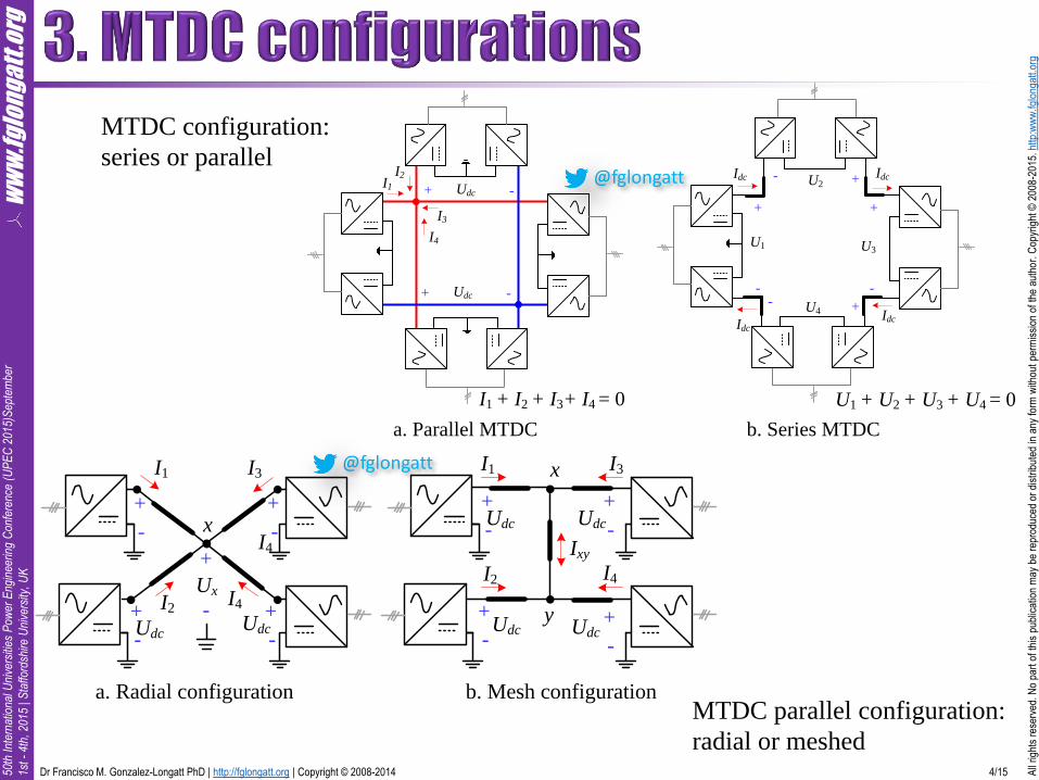
MTDC configuration:
series or parallel
MTDC parallel configuration:
radial or meshed
I1
I2
I3
I4
I1 + I2 + I3+ I4 = 0
U1
U2
U3
U4
U1 + U2 + U3 + U4 = 0
Idc
b. Series MTDCa. Parallel MTDC
+ -Udc
+
-
+-
+
-+-
IdcIdc
Idc
+ -Udc
I1
Udc
+
-
+
-
+
-
+
-
I3
I2 I4
Udc
Udc
Udc
Ixy
y
x
x
+
-Udc
+
-
+
-
+
-
Udc
I1 I3
I4+
-
UxI2
I4
b. Mesh configurationa. Radial configuration
@fglongatt
@fglongatt

www.fglongatt.org
Dr Francisco M. Gonzalez-Longatt PhD | http://fglongatt.org | Copyright © 2008-2014 5/1550th
Inte
rnat
iona
l Uni
vers
ities
Pow
er E
ngin
eerin
g C
onfe
renc
e (U
PE
C20
15)S
epte
mbe
r
1st -
4th,
201
5 | S
taffo
rdsh
ire U
nive
rsity
, UK
All
right
s re
serv
ed. N
o pa
rt o
f thi
s pu
blic
atio
n m
ay b
e re
prod
uced
or
dist
ribut
ed in
any
form
with
out
perm
issi
on o
f the
aut
hor.
Cop
yrig
ht ©
200
8-20
15. h
ttp:w
ww
.fglo
ngat
t.org
• System Configuration:
• A simple MTDC test system is used in this paper for demonstrativespurposes:3-terminal, ±200kVdc, VSC-HVDC.
• Network Model: DC cable between two nodes (e.g. i and j) arerepresented using a single series resistor Rij. DC side of converter stationsare modelled by an ideal dependant voltage source and ideal ground isrepresented as an ideal point where voltages is zero. All electricalquantities are represented using per unit systems. The mathematicmodelling of some grounding configuration of MTDC systems arepresented here.
GSC1
N1
GSC2
N2
N3
WFC1
PWF1 = 0.80 p.u
WF1
AC1
AC2R
12 =
0.0
.073
Test system:
Values of resistors Rij are shown in
p.u
www.fglongatt.org
Dr Francisco M. Gonzalez-Longatt PhD | http://fglongatt.org | Copyright © 2008-2014 6/1550th
Inte
rnat
iona
l Uni
vers
ities
Pow
er E
ngin
eerin
g C
onfe
renc
e (U
PE
C20
15)S
epte
mbe
r
1st -
4th,
201
5 | S
taffo
rdsh
ire U
nive
rsity
, UK
All
right
s re
serv
ed. N
o pa
rt o
f thi
s pu
blic
atio
n m
ay b
e re
prod
uced
or
dist
ribut
ed in
any
form
with
out
perm
issi
on o
f the
aut
hor.
Cop
yrig
ht ©
200
8-20
15. h
ttp:w
ww
.fglo
ngat
t.org
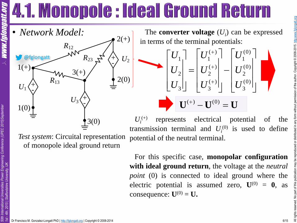
• Network Model:
Test system: Circuital representation
of monopole ideal ground return
2(+)R12
R23
R13
1(+)3(+)
U2
U1
U3
+-
+-
1(0)
2(0)
3(0)
+-
( ) (0)
1 1 1
( ) (0)
2 2 2
( ) (0)
3 3 3
U U U
U U U
U U U
The converter voltage (Ui) can be expressed
in terms of the terminal potentials:
Ui(+) represents electrical potential of the
transmission terminal and Ui(0) is used to define
potential of the neutral terminal.
For this specific case, monopolar configuration
with ideal ground return, the voltage at the neutral
point (0) is connected to ideal ground where the
electric potential is assumed zero, U(0) = 0, as
consequence: U(0) = U.
( ) (0) U U U
@fglongatt

www.fglongatt.org
Dr Francisco M. Gonzalez-Longatt PhD | http://fglongatt.org | Copyright © 2008-2014 7/1550th
Inte
rnat
iona
l Uni
vers
ities
Pow
er E
ngin
eerin
g C
onfe
renc
e (U
PE
C20
15)S
epte
mbe
r
1st -
4th,
201
5 | S
taffo
rdsh
ire U
nive
rsity
, UK
All
right
s re
serv
ed. N
o pa
rt o
f thi
s pu
blic
atio
n m
ay b
e re
prod
uced
or
dist
ribut
ed in
any
form
with
out
perm
issi
on o
f the
aut
hor.
Cop
yrig
ht ©
200
8-20
15. h
ttp:w
ww
.fglo
ngat
t.org
The current injected (Ii) is written into a matrix form using the conductance matrix (G) of
the DC grid can be used:
( )
1 11 12 13 1
( )
2 21 22 23 2
( )
3 31 32 33 3
I G G G U
I G G G U
I G G G U
( )I GU I GU
where the DC current vector I = [I,1, I2, ...,Idc,ndc]T, U = [U1, U2, ...,Undc]
T is the DC voltage
vector and G is also known as the DC nodal admittance matrix (Gij, i, j = 1, …ndc).
The current injections I are not known prior to the power flow solution for the DC network.
The vector P = [P1, P2, ...,Pndc]T, which refers to power flow into the DC grid via the DC
terminals, is given by
where the symbol is entry-wise (point-to-point) matrix multiplication operator.
Equation is known as the power balance equation and it can be solved in order to obtain
the classical power flow solution of the MTDC system.
I = GU
P = U GU

www.fglongatt.org
Dr Francisco M. Gonzalez-Longatt PhD | http://fglongatt.org | Copyright © 2008-2014 8/1550th
Inte
rnat
iona
l Uni
vers
ities
Pow
er E
ngin
eerin
g C
onfe
renc
e (U
PE
C20
15)S
epte
mbe
r
1st -
4th,
201
5 | S
taffo
rdsh
ire U
nive
rsity
, UK
All
right
s re
serv
ed. N
o pa
rt o
f thi
s pu
blic
atio
n m
ay b
e re
prod
uced
or
dist
ribut
ed in
any
form
with
out
perm
issi
on o
f the
aut
hor.
Cop
yrig
ht ©
200
8-20
15. h
ttp:w
ww
.fglo
ngat
t.org
2(+)R12
R23
R13
1(+)3(+)
U2
U1
U3
+-
+-
Rgnd1
1(0)
2(0)
Rgnd2
Rgnd3
3(0)
+-
Test system: Circuital representation
of monopole with real ground return
(Rgndi).
The potential of the neutral points (0) are calculated
based on the grounding resistors (Rgndi):
(0)
1 1 1
(0)
2 2 2
(0)
3 3 3
0 0
0 0
0 0
gnd
gnd
gnd
U R I
U R I
U R I
( )
1 1 1 1
( )
2 2 2 2
( )
3 3 3 3
0 0
0 0
0 0
gnd
gnd
gnd
U U R I
U U R I
U U R I
( ) (0)
1 1 1
( ) (0)
2 2 2
( ) (0)
3 3 3
U U U
U U U
U U U
(0) gndU R I
( ) gndU U R I
@fglongatt

www.fglongatt.org
Dr Francisco M. Gonzalez-Longatt PhD | http://fglongatt.org | Copyright © 2008-2014 9/1550th
Inte
rnat
iona
l Uni
vers
ities
Pow
er E
ngin
eerin
g C
onfe
renc
e (U
PE
C20
15)S
epte
mbe
r
1st -
4th,
201
5 | S
taffo
rdsh
ire U
nive
rsity
, UK
All
right
s re
serv
ed. N
o pa
rt o
f thi
s pu
blic
atio
n m
ay b
e re
prod
uced
or
dist
ribut
ed in
any
form
with
out
perm
issi
on o
f the
aut
hor.
Cop
yrig
ht ©
200
8-20
15. h
ttp:w
ww
.fglo
ngat
t.org
( )
1 1 1 1
( )
2 2 2 2
( )
3 3 3 3
0 0
0 0
0 0
gnd
gnd
gnd
U U R I
U U R I
U U R I
( ) gndU U R I
1 1( )
gnd gnd
I R U R U( ) gndU U R IThe conductance matrix (G)
( )I GU( ) 1 U G I
1 11
gnd gnd
I R G I R U
1 11
gnd gnd
ones R G I R U
11 1
1
gnd gnd
I ones R G R UFinally the power balance
equations for this configuration
is described by:
11 1
1
gnd gndP = U ones R G R U

www.fglongatt.org
Dr Francisco M. Gonzalez-Longatt PhD | http://fglongatt.org | Copyright © 2008-2014 10/1550th
Inte
rnat
iona
l Uni
vers
ities
Pow
er E
ngin
eerin
g C
onfe
renc
e (U
PE
C20
15)S
epte
mbe
r
1st -
4th,
201
5 | S
taffo
rdsh
ire U
nive
rsity
, UK
All
right
s re
serv
ed. N
o pa
rt o
f thi
s pu
blic
atio
n m
ay b
e re
prod
uced
or
dist
ribut
ed in
any
form
with
out
perm
issi
on o
f the
aut
hor.
Cop
yrig
ht ©
200
8-20
15. h
ttp:w
ww
.fglo
ngat
t.org
The power balance equations of other grounding configuration are created using the same
mathematical procedure presented before.
2(+)R12
2(-)
R23
R13
1(+)
1(-)
3(+)
3(-)
R12R23
R13
U2
U1
U3
+-
+-
+-
U1+-
+-
+-
U3
U2
Rgnd1
1(0)
3(0)
2(0)Rgnd2
Rgnd3
2(+)R12
2(-)
R23
R13
1(+)
1(-)
3(+)
3(-)
R12R23
R13
U2
U1
U3
+-
+-
+-
U1+-
+-
+-
U3
U21(0)
3(0)
2(0)
Test system: Circuital representation: Bipolar
ground return
Test system: Circuital
representation: Bipolar Metallic
return
@fglongatt
@fglongatt

www.fglongatt.org
Dr Francisco M. Gonzalez-Longatt PhD | http://fglongatt.org | Copyright © 2008-2014 11/1550th
Inte
rnat
iona
l Uni
vers
ities
Pow
er E
ngin
eerin
g C
onfe
renc
e (U
PE
C20
15)S
epte
mbe
r
1st -
4th,
201
5 | S
taffo
rdsh
ire U
nive
rsity
, UK
All
right
s re
serv
ed. N
o pa
rt o
f thi
s pu
blic
atio
n m
ay b
e re
prod
uced
or
dist
ribut
ed in
any
form
with
out
perm
issi
on o
f the
aut
hor.
Cop
yrig
ht ©
200
8-20
15. h
ttp:w
ww
.fglo
ngat
t.org
• The steady-state performance of a MTDC system is described bythe power flow, it is be described by a set of nonlinear algebraicequations:
• where G is the set of algebraic equations define the power-balanceat network nodes as shown in previous Sections, and X is statevector and Y is the vector of independent variable and Z is a vectorof control variables.
Bound constraints:
, , G X Y Z 0
min maxiU U U
Nonlinear equality constraints:
Inverter
mode
Umax
DC
volt
age,
Ud
c
Umin
Pmax0-Pmax
Uref
Rectifier
mode
DC Power, Pdc 1
dc ref ref dc
DC
U U P PR
Linear inequalities:
max
conv dc dc convI = Y U I
Power Balance Equations

www.fglongatt.org
Dr Francisco M. Gonzalez-Longatt PhD | http://fglongatt.org | Copyright © 2008-2014 12/1550th
Inte
rnat
iona
l Uni
vers
ities
Pow
er E
ngin
eerin
g C
onfe
renc
e (U
PE
C20
15)S
epte
mbe
r
1st -
4th,
201
5 | S
taffo
rdsh
ire U
nive
rsity
, UK
All
right
s re
serv
ed. N
o pa
rt o
f thi
s pu
blic
atio
n m
ay b
e re
prod
uced
or
dist
ribut
ed in
any
form
with
out
perm
issi
on o
f the
aut
hor.
Cop
yrig
ht ©
200
8-20
15. h
ttp:w
ww
.fglo
ngat
t.org
• VSC-HVDC terminals:
• Constant power control mode on the wind farm converter station(P3)
• DC voltage droop control on the grid side converter stations (U1
and U2, DC1 = 0.0005 and DC2 = 0.0002 p.u/MW), thus enablingN-1 security.
GSC1
N1
GSC2
N2
N3
WFC1
PWF1 = 0.80 p.u
WF1
AC1
AC2R
12 =
0.0
.073

www.fglongatt.org
Dr Francisco M. Gonzalez-Longatt PhD | http://fglongatt.org | Copyright © 2008-2014 13/1550th
Inte
rnat
iona
l Uni
vers
ities
Pow
er E
ngin
eerin
g C
onfe
renc
e (U
PE
C20
15)S
epte
mbe
r
1st -
4th,
201
5 | S
taffo
rdsh
ire U
nive
rsity
, UK
All
right
s re
serv
ed. N
o pa
rt o
f thi
s pu
blic
atio
n m
ay b
e re
prod
uced
or
dist
ribut
ed in
any
form
with
out
perm
issi
on o
f the
aut
hor.
Cop
yrig
ht ©
200
8-20
15. h
ttp:w
ww
.fglo
ngat
t.org
A MATLAB® R2014a (64-bit) program (m-file) has been developed for this very
specific propose. Interior-point algorithm is used to solve the optimization problem in
this paper. Bound constraints are considered in all simulations in order to ensure a secure
system operation (0.90 < Udc < 1.10 p.u).
Numerical results of N-1 contingency analysis in DIgSILENT PowerFactory v15.2.4 are
used for comparative purposes.
(Rgnd1 = 1, Rgnd2 = 2, Rgnd3 = 3).
1dc(+)
2dc(-)
3dc(-)
2dc(+)
3dc(+)
1dc(+)
3dc(-)
-106.0 kV-1.06003 p.u.
0.0 deg
2dc(-..
-105.5 kV-1.05533 p.u.
0.0 deg
1dc(-..
-104.7 kV-1.04712 p.u.
0.0 deg
3dc(+)
106.0 kV1.06003 p.u.
0.0 deg
2dc(+)
105.5 kV1.05533 p.u.
0.0 deg
1dc(+)
104.7 kV1.04712 p.u.
0.0 deg
3ac
100.0 kV1.00000 p.u.
0.0 deg
2ac
100.0 kV1.0000..0.0 deg
1ac
100.0 kV1.00000 p.u.
0.0 deg
fglongatt.org
PowerFactory 15.2.4
GROUNDING AND CONFIGURATION OF MTDC
Symetric Bipolar-Earth Return Multi-terminal HVDC Prof. Francisco M. Gonzalez-Longatt
Project: MTDC
Graphic: Grid
Date: 6/4/2015
Annex:
Grid: Summary Grid
Generation = 400.00 MW 0.00 Mvar 400.00 MVA External Infeed = -394.93 MW 0.00 Mvar 394.93 MVA
Inter Area Flow = 0.00 MW 0.00 Mvar Load P(U) = 0.00 MW 0.00 Mvar 0.00 MVA Load P(Un) = 0.00 MW 0.00 Mvar 0.00 MVA
Load P(Un-U) = 0.00 MW 0.00 Mvar Motor Load P = 0.00 MW 0.00 Mvar 0.00 MVA
Losses = 5.07 MW 0.00 Mvar Line Charging = 0.00 Mvar
Compensation ind. = 0.00 Mvar Compensation cap. = 0.00 Mvar Installed Capacity = 500.00 MW Spinning Reserve = 100.00 MW
Total Power Factor: Generation = 1.00 [-]
Load/Motor = 0.00 / 0.00 [-]
-0.0 kV-0.00000 p.u.
0.0 deg
-0.0 kV-0.00000 p.u.
0.0 deg
-0.0 kV-0.00000 p.u.
0.0 deg
Rb(.
.188..
Ra(.
.188..
Rgnd30.0G
ND
3
0.00.0
0.000
Rb(.
.11.1
Ra(.
.11.1
Rgnd20.0
GN
D2
0.00.0
0.000
GS
C2(-
)
-11.7-0.0
0.067
0.00.0
0.111
11.70.0
-0.111
WF
C1(-
)
-200.0-0.0
1.155
0.00.0
1.887
200.00.0
-1.887
GS
C1(-
)
209.10.0
1.207
0.00.0
-1.997
-209.10.0
1.997
Rb
199..
Ra
199..
Rgnd10.0
GN
D1
0.00.0
0.000
WF
C1(+
)
-200.0-0.0
1.155
200.00.0
1.887
0.00.0
-1.887
GS
C2(+
)
-11.7-0.0
0.067
11.70.0
0.111
0.00.0
-0.111
GS
C1(+
)
209.10.0
1.207
-209.10.0
-1.997
0.00.0
1.997
Cable
12(-
)19.5
-58.90.0
0.563
59.40.0
-0.563
Cable
23(-
)15.7
47.90.0
-0.452
-47.70.0
0.452
Cable
13(-
)49.7
-150.20.0
1.435
152.10.0
-1.435
Cable
12(+
)19.5
-58.90.0
-0.563
59.40.0
0.563Cable23(+)
15.7
47.90.0
0.452
-47.70.0
-0.452
Cable
13(+
)49.7
-150.20.0
-1.435
152.10.0
1.435
WF180.0
400.00.0
2.309
V~
AC2
23.30.0
0.135
V~
AC1
-418.3-0.0
2.415
DIg
SIL
EN
T

www.fglongatt.org
Dr Francisco M. Gonzalez-Longatt PhD | http://fglongatt.org | Copyright © 2008-2014 14/1550th
Inte
rnat
iona
l Uni
vers
ities
Pow
er E
ngin
eerin
g C
onfe
renc
e (U
PE
C20
15)S
epte
mbe
r
1st -
4th,
201
5 | S
taffo
rdsh
ire U
nive
rsity
, UK
All
right
s re
serv
ed. N
o pa
rt o
f thi
s pu
blic
atio
n m
ay b
e re
prod
uced
or
dist
ribut
ed in
any
form
with
out
perm
issi
on o
f the
aut
hor.
Cop
yrig
ht ©
200
8-20
15. h
ttp:w
ww
.fglo
ngat
t.org
• Minimal numerical discrepancies between the DIgSILENTPowerFactory and proposed method. The largest numericaldifference in post-contingency states is below 0.002 p.u, asconsequence, the proposed method can be used with minordiscrepancies.
NodeVoltage (p.u)
DIgSILENT
Voltage (p.u)
MATLABContingency
3dc(-) -1.0791 -1.0791 Cable13(-)
2dc(-) -1.0600 -1.0598 Cable13(-)
1dc(-) -1.0510 -1.0508 Cable23(-)
3dc(+) 1.0791 1.0791 Cable13(+)
2dc(+) 1.0600 1.0598 Cable13(+)
1dc(+) 1.0510 1.0508 Cable23(+)
DC cable outage is an important contingency because create an important change on the
power flows (magnitudes and directions) in the DC-transmission system and post-
contingency is interesting from the grounding point of view.
SIMULATION RESULTS OF N-1 CONTINGENCY ANALYSIS: CABLES OUTAGE. BIPOLAR EARTH
RETURN CONFIGURATION

www.fglongatt.org
Dr Francisco M. Gonzalez-Longatt PhD | http://fglongatt.org | Copyright © 2008-2014 15/1550th
Inte
rnat
iona
l Uni
vers
ities
Pow
er E
ngin
eerin
g C
onfe
renc
e (U
PE
C20
15)S
epte
mbe
r
1st -
4th,
201
5 | S
taffo
rdsh
ire U
nive
rsity
, UK
All
right
s re
serv
ed. N
o pa
rt o
f thi
s pu
blic
atio
n m
ay b
e re
prod
uced
or
dist
ribut
ed in
any
form
with
out
perm
issi
on o
f the
aut
hor.
Cop
yrig
ht ©
200
8-20
15. h
ttp:w
ww
.fglo
ngat
t.org
• Case I: bipolar ideal earth return (Rgnd =0).
• Case II, bipolar earth return (Rgnd1 = 1, Rgnd2 = 2, Rgnd3 = 3)
• Case III: bipolar (no ground return).
Simulations are based on simple contingency, DC cable outage.
• Case I, ideal return: the lowest post contingency DC voltages.
• It should be noticed the use of bipolar configuration without any grounding connection
provides the highest post-contingency DC voltages.
• It must recognised the benefits of using earth path return in asymmetrical DC systems.
• There are two major positive impacts: it helps to control post-contingency dc voltages
and also provided alternative current path helping on the power flow distribution on
weakly connected DC terminals.
Node Case I Case II Case III Contingency
3dc(-) -1.0783 -1.0791 -1.0884 Cable13(-)
2dc(-) -1.0590 -1.0598 -1.0706 Cable13(-)
1dc(-) -1.0512 -1.0508 -1.0595 Cable23(-)
3dc(+) 1.0783 1.0791 1.0884 Cable13(+)
2dc(+) 1.0590 1.0598 1.0706 Cable13(+)
1dc(+) 1.0512 1.0508 1.0595 Cable23(+)
RESULTS COMPARISON OF N-1 CONTINGENCY ANALYSIS: GROUNDING

www.fglongatt.org
Dr Francisco M. Gonzalez-Longatt PhD | http://fglongatt.org | Copyright © 2008-2014 16/1550th
Inte
rnat
iona
l Uni
vers
ities
Pow
er E
ngin
eerin
g C
onfe
renc
e (U
PE
C20
15)S
epte
mbe
r
1st -
4th,
201
5 | S
taffo
rdsh
ire U
nive
rsity
, UK
All
right
s re
serv
ed. N
o pa
rt o
f thi
s pu
blic
atio
n m
ay b
e re
prod
uced
or
dist
ribut
ed in
any
form
with
out
perm
issi
on o
f the
aut
hor.
Cop
yrig
ht ©
200
8-20
15. h
ttp:w
ww
.fglo
ngat
t.org
• Selection of final grounding scheme and grounding resistorsrequires a complete DC system analysis.
• Grounding configuration affects the performance of the MTDCsystem virtually in any possible mode: normal (asymmetricaloperation) and abnormal operation (faults), steady-state anddynamic.
• This paper has two contribution
1. to introduce a simple optimization-based-approach to calculate the steady-state post-contingency of MTDC systems and
2. to use that approach in order to illustrate basic effects of groundingconfigurations on steady-state post-contingency performance.
• A 3-terminal HVDC system is used to formulate the maintheoretical framework for performance prediction on post-contingency steady-state of MTDC system as well as fordemonstrative purposes.

www.fglongatt.org
Dr Francisco M. Gonzalez-Longatt PhD | http://fglongatt.org | Copyright © 2008-2014 17/1550th
Inte
rnat
iona
l Uni
vers
ities
Pow
er E
ngin
eerin
g C
onfe
renc
e (U
PE
C20
15)S
epte
mbe
r
1st -
4th,
201
5 | S
taffo
rdsh
ire U
nive
rsity
, UK
All
right
s re
serv
ed. N
o pa
rt o
f thi
s pu
blic
atio
n m
ay b
e re
prod
uced
or
dist
ribut
ed in
any
form
with
out
perm
issi
on o
f the
aut
hor.
Cop
yrig
ht ©
200
8-20
15. h
ttp:w
ww
.fglo
ngat
t.org