Effects of elastic strain energy and interfacial stress on...
28
Effects of elastic strain energy and interfacial stress on the equilibrium morphology of misfit particles in heterogeneous solids Xujun Zhao 1 , Ravindra Duddu 3 , Stéphane P.A. Bordas 4 and Jianmin Qu 1,2 1 Department of Mechanical Engineering, Northwestern University, Evanston, IL USA 60208. 2 Department of Civil and Environmental Engineering, Northwestern University, Evanston, IL USA 60208. 3 Department of Civil and Environmental Engineering, Vanderbilt University, Nashville, TN USA 37235. 4 Cardiff School of Engineering, Institute of Mechanics and Advanced Materials Theoretical, Applied and Computational Mechanics, Cardiff University, The Parade, Cardiff CF24 3AA, Wales, UK. Abstract This paper presents an efficient sharp interface model to study the morphological transformations of misfit particles in phase separated alloys. Both the elastic anisotropy and interfacial energy are considered. The geometry of the material interface is implicitly described by the level set method so that the complex morphological transformation of microstructures can be accurately captured. A smoothed extended finite element method is adopted to evaluate the elastic field without requiring remeshing. The equilibrium morphologies of particles are shown to depend on the elastic anisotropy, interfacial energy as well as the particle size. Various morphological transformations, such as shape changes from spheres to cuboids, directional aligned platelets and particle splitting, are observed. The simulated results are in good agreement with experimental observations. The proposed model provides a useful tool in understanding the morphological transformation of precipitates, which will facilitate the analysis and design of metallic alloys. Keywords: Morphological transformation; Particle splitting; Equilibrium shape; Extended finite element method; Level set method; corresponding author: [email protected] 1
Transcript of Effects of elastic strain energy and interfacial stress on...

Effects of elastic strain energy and interfacial stress on the equilibrium morphology of misfit particles in heterogeneous solids Xujun Zhao1, Ravindra Duddu3, Stéphane P.A. Bordas4 and Jianmin Qu1,2
1Department of Mechanical Engineering, Northwestern University, Evanston, IL USA 60208. 2Department of Civil and Environmental Engineering, Northwestern University, Evanston, IL
USA 60208. 3Department of Civil and Environmental Engineering, Vanderbilt University, Nashville, TN
USA 37235. 4Cardiff School of Engineering, Institute of Mechanics and Advanced Materials Theoretical,
Applied and Computational Mechanics, Cardiff University, The Parade, Cardiff CF24 3AA,
Wales, UK.
Abstract
This paper presents an efficient sharp interface model to study the morphological
transformations of misfit particles in phase separated alloys. Both the elastic
anisotropy and interfacial energy are considered. The geometry of the material
interface is implicitly described by the level set method so that the complex
morphological transformation of microstructures can be accurately captured. A
smoothed extended finite element method is adopted to evaluate the elastic field
without requiring remeshing. The equilibrium morphologies of particles are shown to
depend on the elastic anisotropy, interfacial energy as well as the particle size. Various
morphological transformations, such as shape changes from spheres to cuboids,
directional aligned platelets and particle splitting, are observed. The simulated results
are in good agreement with experimental observations. The proposed model provides
a useful tool in understanding the morphological transformation of precipitates, which
will facilitate the analysis and design of metallic alloys.
Keywords: Morphological transformation; Particle splitting; Equilibrium shape;
Extended finite element method; Level set method;
corresponding author: [email protected]
1

1. Introduction
Since the macroscopic properties of heterogeneous materials are closely related to
their underlying microstructures, morphologies of the microstructures in
heterogeneous materials have been of great interest for material design and
constitutive modeling. In particular, new types of precipitate strengthened alloys with
desired mechanical properties can be designed by controlling the morphologies of
precipitates. Many different morphological transformations have been reported in a
number of phase-separated alloys. For example, it was experimentally observed that
second phase particles in Ni-based superalloys undergo shape changes from spheres
to cuboids with round corners, to platelets aligned along crystallographic directions
when the superalloys are annealed at some specific temperature below the
precipitation line (Fahrmann et al., 1995; Maheshwari and Ardell, 1993). In addition,
more complex phenomena of morphological transformations, such as splitting of a
single large particle into several small ones and coalescence of small particles to form
highly non-equiaxed plates, have also been found in experiments (Doi et al., 1984; Ma
and Ardell, 2007; Miyazaki et al., 1982). Therefore, in order to design new alloys with
stable material properties, it is desirable to understand the equilibrium morphologies
of microstructures at different length scales.
It has been experimentally demonstrated that both the elastic strain energy and the
interfacial energy play important roles on the microstructural morphologies (Conley et
al., 1989; Fahrmann et al., 1995). The former is caused by the lattice misfitting
between the precipitate and matrix and the latter is due to the existence of
particle-matrix interfaces. From the thermodynamic point of view, the equilibrium
morphology of particles in this elastically constrained system is achieved by
minimizing the total system free energy, i.e. the sum of elastic strain energy and
interfacial energy. As a result, the elastic constants and anisotropy of the two phases
involved, as well as the interfacial quantities, will affect the equilibrium morphology.
For a detailed review, the reader is referred to (Doi, 1996). It should be mentioned that
the interfacial energy for solid materials is generally deformation dependent rather
2

than constant, which differs from that of liquids (Cammarata and Sieradzki, 1994;
Dingreville et al., 2005).
The difficulties in modeling microstructure evolution in phase separated alloys stem
from the facts that (i) material properties are discontinuous across the
precipitate-matrix interface; and (ii) topological changes of interface during the
transformation are difficult to capture numerically. General approaches for simulating
the morphological development of particles can be broadly classified on the basis of
how the interface is resolved, and are known as diffuse interface and sharp interface
models; and how the interface is represented: Lagrangian and Eulerian descriptions.
The diffuse interface model, using an Eulerian description (e.g. phase field method)
describes the geometrical interface utilizing an order parameter that smoothly changes
across the interface so that the location of the interface is not tracked. This approach is
advantageous in simulating microstructural evolution with interaction of multiple
particles and topological changes, such as particle coalescence and splitting (Hu and
Chen, 2001; Lou and Bassani, 2008; Wang et al., 1993). Nevertheless, the main
drawback of such diffuse interface models is that their computations are very complex,
because the diffuse interface must be resolved by using a grid spacing smaller than the
interface thickness to ensure accuracy (Provatas and Elder, 2010). Typically, in real
materials, the particle-matrix interface thickness is infinitesimally small compared to
the particle size, which necessitates a very refined mesh. Furthermore, the parameters
involved in the phase field equations are usually difficult to determine for realistic
materials.
By contrast, the sharp interface approaches use a dividing interface to distinguish the
two separate phases. For example, the equilibrium shapes of misfitting particles in an
elastically anisotropic system have been formulated based on the boundary integral
methods (BIM), in which the interface was explicitly tracked by marker particles
(Schmidt and Gross, 1997; Schmidt et al., 1998; Su and Voorhees, 1996; Voorhees et
3

al., 1992). Jog et al. (Jog et al., 2000) proposed a general approach for determining the
equilibrium shape of isolated misfitting particles by minimizing the sum of elastic and
interfacial energy using a combination of finite element method (FEM) and an
optimization technique. However, for the conventional BIM and FEM based
approaches using a Lagrangian particle tracking method, a set of marker points have
to be placed on the interfaces to track its motion so it is extremely difficult to handle
topological changes such as particle merging and breaking, which have been
extensively observed in actual experiments (Doi et al., 1984; Kaufman et al., 1989;
Miyazaki et al., 1982).
The present work is to study the equilibrium morphologies of inhomogeneities in a
generally anisotropic elastic solid with arbitrary misfit strains without any a priori
assumption of the possible precipitate morphologies. The interfacial energy is
assumed deformation-dependent and is taken into account by using the Gurtin and
Murdoch interface elasticity model (Gurtin and Murdoch, 1975). We employ a sharp
interface model based on a hybrid extended finite element and level set method that
naturally allows complex topological changes during the morphological evolution
without requiring remeshing. The level set method, originally devised for tracking
moving interfaces (Osher and Sethian, 1988), is capable of describing complicated
geometrical interfaces of microstructures, such as dendritic solidification (Chen et al.,
1997; Zabaras et al., 2006), precipitate evolution (Duddu et al., 2011) and biofilm
growth (Duddu et al., 2008; Duddu et al., 2009).. The combined method enables the
handling of complex morphological transformations of multiple misfitting
inhomogeneities. The extended finite element method (XFEM) (Moës et al., 2003;
Moës et al., 1999) is used to compute the elastic field of the particle-matrix system
with the interface elasticity effect. The main advantage of XFEM is that the meshes
are not required to conform with the geometrical interface, so that remeshing is not
needed when the interface moves. The equilibrium morphologies of particles are
obtained by minimizing the sum of elastic strain energy and interfacial energy at a
constant total mass of the particles. We show that the complex morphological
4

transformations observed in experiments, such as splitting and merging, can be
accurately captured for different particle sizes.
2. Problem formulation
We consider a generally anisotropic elastic solid V containing a number of
inhomogeneous particles with arbitrary eigenstrains. Assume the particles occupy
domain with arbitrary shape bounded by the smooth interface . The
particle-matrix interfaces are assumed to be coherent and the external boundary of V
is subjected to traction-free boundary conditions. In the absence of body force, the
governing equations of the elastic bulk materials are as follows:
0 σ (1)
[ ( ) ] ( ) : ( )
( )
I *
M
C : ε x - ε xσ C x e x
C : ε x x (2)
1
2T ε = u + u (3)
where denotes the displacement vector, σ and are the stress and strain
tensors, respectively, is the elastic strain tensor, is the eigenstrain tensor that
measures the lattice misfit between the particle and matrix, and and
represent the elastic stiffness tensors of inhomogeneity and matrix respectively.
u ε
e *ε
IC MC
Due to the existence of interfacial stress, the mechanical equilibrium conditions on the
interface are governed by the generalized Young-Laplace equation (Gurtin and
Murdoch, 1975; Povstenko, 1993)
0S σ n σ (4)
where ( ) ( )out in represents the quantity jump across the interface, is
outward normal, and is interfacial stress. The displacement across the
particle-matrix interface of coherent particles is continuous, i.e.
n
Sσ
0u (5)
5
The total system free energy is given by the sum of the elastic strain energy and the
interfacial energy
VF WdV dS
(6)
where 1
2W σ : e is the elastic strain energy density, and is the interfacial
energy density, which can be written as (Dingreville et al., 2005)
0
1: :
2S S S S S τ ε ε C ε: (7)
Field quantities with a superscript S in the above equation are associated with the
interfaces. For example, is the interface strain tensor, is the interface elastic
stiffness tensor, is the interface residual stress, and
Sε SC
0Sτ is the interfacial free
energy density that corresponds to the interfacial energy state when . The
interfacial strain can be computed from
S ε 0
1( ) ( )
2s
s s ε P u u PT (8)
where is the projection tensor, I is the identity tensor, represents a
dyad, and the surface gradient is defined as
P I n n
s u u P . Consequently, the
corresponding interfacial stress can be obtained from the Shuttleworth equation
(Shuttleworth, 1950),
:SS
S S S
τ Cσε
ε (9)
In the early stage of phase decomposition, a new phase nucleates from the matrix and
grows by absorbing the supersaturated solute atoms from its neighboring substrate
until the solute concentration in the matrix decreases to the equilibrium state. When
the formation of a new phase is finished, the matrix can no longer provide solute
atoms to the precipitates. Therefore, the mass fraction remains constant during the
subsequent aging, although the morphology of particles will continue to change to
adjust the total system energy. During this process, the chemical free energy can be
reasonably assumed to remain constant. Therefore, the total system energy is the sum
of the elastic energy and interfacial energy, and the equilibrium morphology depends
on the balance of elastic energy and interfacial energy (Doi, 1996). Based on the
above assumptions, the problem can be modeled by minimizing the total energy under
the constraint that the mass fraction remains constant, which is equivalent to the
6

constraint that the volume fraction remains constant for the small deformation
considered here. As a result, the energy functional can be modified by
incorporating a Lagrangian multiplier
F
0VF WdV dS dV V
(10)
where is the prescribed total volume of particles. It has been shown that the
Lagrangian multiplier
0V
can be identified as a chemical driving force, which is the
jump of chemical free energy density across the interface (Schmidt and Gross, 1997).
Therefore, the present problem becomes a minimization problem, i.e., searching a
minimum of energy functional F subjected to the mechanical equilibrium equations
(1)-(5).
3. Kinetics of the interface
To derive the driving force on the interface, let us introduce a fictitious time . In
continuum mechanics, the material derivative of a quantity is usually denoted as
consisting of two parts: the first part consists of the local rate of the
quantity change at a fixed material point and the second part is related to changes due
to variation of the domain itself. For example, the material derivative of the
displacement vector can be written as
t
/D Dt
D
Dt t
u uu v (11)
where is the velocity vector. For simplicity, we use ‘over dot’ and a
‘prime’ to represent the material derivative and local derivative, respectively, which
leads to
/d dtv x
u u u v (12)
According to the Reynolds transport theorem (Belytschko et al., 2000), taking the
material derivative of the elastic energy functional yields
( )
: : ( )
V V
V
D WWdV div W dV
Dt t
div W dV
v
σ u σ u v v (13)
7

Using the Green’s theorem, the above equation becomes
:V V
DWdV dV dS
Dt σ u n Σ v (14)
where
W Σ I σ u (15)
is Eshelby’s elastic energy momentum tensor (Eshelby, 1975).
The material derivative of the interfacial energy density gives rise to
:
nV
SS n
DdV v dS
Dt
dS v dS
σ u
(16)
where is the normal velocity and nv v n is the interface mean curvature. The
material derivative of the volume integral is straightforward,
nV
DdV v dS
Dt (17)
Therefore, the material derivative of the energy functional (10), by using equations
(15), (16) and (17), can be easily obtained as follows:
: :SSV
DFdV dS v dS
Dt
σ u σ u n Σ n n (18)
Since is an arbitrary variation which can be treated as a test function that u u u ,
it is obvious that the first two integrals of above equation are the weak forms of
equilibrium equations (1)-(5), and should vanish when the system arrives at
mechanical equilibrium. This can be illustrated as follows:
: :
0
SSV
S SS SV
SSV
dV dS
dV dS
dV dS
σ u σ u
σ u σ u σ u σ u
σ u σ n σ u
(19)
Consequently, equation (18) reduces to
n
DFv dS
Dt
n Σ n (20)
If we take
8
nv n Σ n (21)
then equation (20) becomes
2 0n
DFv dS
Dt . (22)
In other words, (21) guarantees that the total system energy always decreases in the
steepest decent direction during the interface evolution. It should be mentioned that
the normal velocity (21) is of the same form as the necessary equilibrium condition in
reference (Schmidt and Gross, 1997). However, our work differs from theirs in two
respects. First, the interfacial energy in the present work is deformation dependent,
which is related to interfacial residual stress and interfacial elasticity. Similarly, the
energy momentum tensor is also affected by the interfacial stress due to the
coupled boundary condition
Σ
(4). Second, it is possible that the necessary equilibrium
condition in (Schmidt and Gross, 1997) may lead to a maximum or a saddle point
unless the sign of the second variation of energy functional is considered. In contrast,
our formulation guarantees that the system always evolves in a direction that
decreases the total system energy, so that at least a local minimum is achieved.
Finally, the Lagrangian multiplier can be obtained from the mass conservation
condition, i.e. 0V
DdV
Dt . Substituting (21) into (17) yields
0dS
n Σ n (23)
Hence, we have
dS
dS
n Σ n
(24)
4. Level set description of implicit interfaces
In practice, complex topological changes take place during the morphological
evolution of single or multiple particles, such as merging and splitting. It is therefore
desirable to describe the geometrical interfaces without an explicit parameterization.
9
Moreover, it is also desirable that the method is capable of dealing with multiple
particles within a uniform framework.
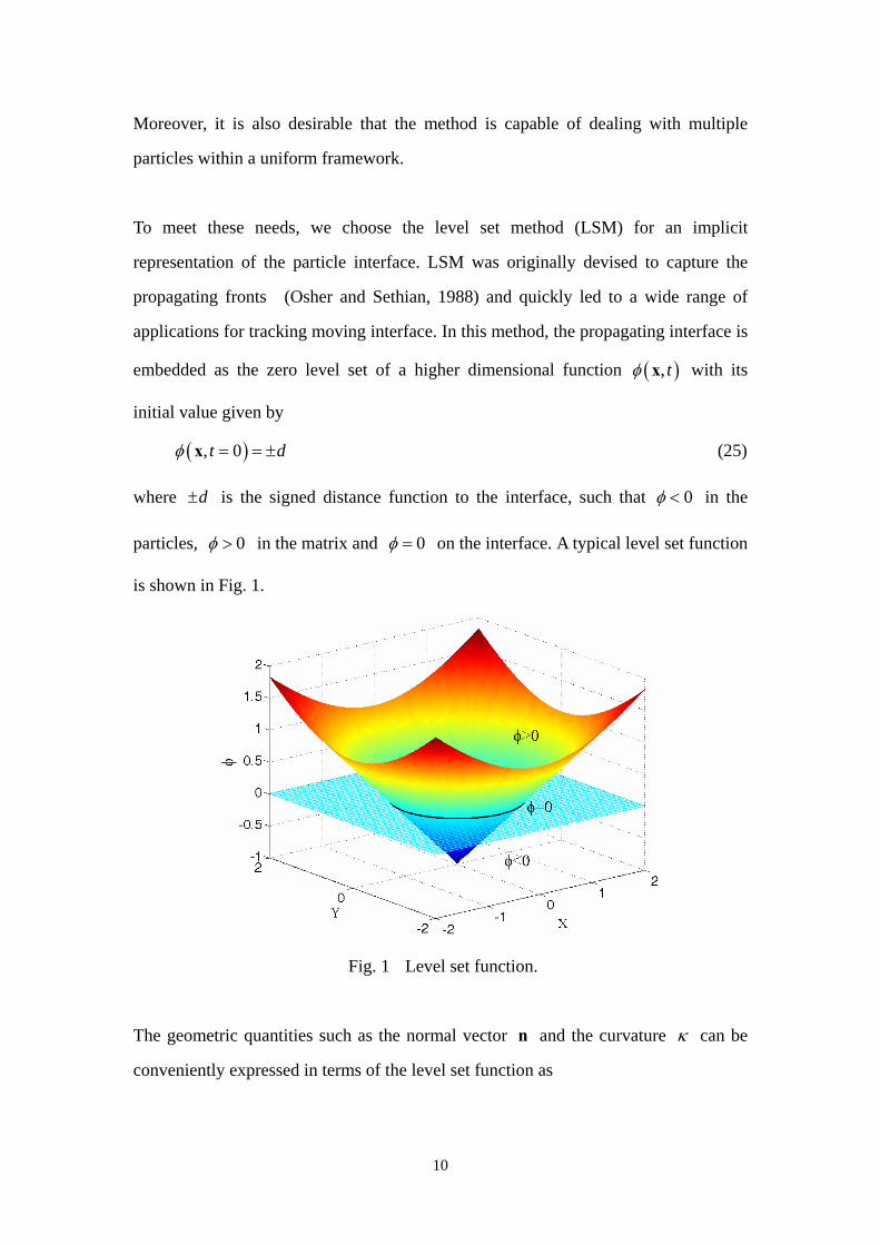
To meet these needs, we choose the level set method (LSM) for an implicit
representation of the particle interface. LSM was originally devised to capture the
propagating fronts (Osher and Sethian, 1988) and quickly led to a wide range of
applications for tracking moving interface. In this method, the propagating interface is
embedded as the zero level set of a higher dimensional function with its
initial value given by
, t x
d , 0t x (25)
where is the signed distance function to the interface, such that d 0 in the
particles, 0 in the matrix and 0 on the interface. A typical level set function
is shown in Fig. 1.
Fig. 1 Level set function.
The geometric quantities such as the normal vector and the curvature can be
conveniently expressed in terms of the level set function as
n
10

n ,
(26)
An initial boundary value partial differential equation then can be obtained for the
evolution of by taking a material derivative on both sides of (25)
0ext
t
v or 0ext
nvt
(27)
which is well known as the level set evolution equation. The position of the interface
at any time t is given by the zero level set , t 0x . Now the equilibrium
morphology problem discussed in the previous section becomes a problem of finding
a scalar function that minimizes the system energy functional F .
It is noted that the velocity field or in the level set equation is defined in
the entire computational domain, while the velocity given in
extv extnv
(21) is only defined on
the interface. Therefore, a velocity extension should be conducted to construct the
velocity field from the interface to the whole computational domain. In this work, a
second order fast marching method (Sethian, 1996, 1999a) is adopted to construct the
spatial velocity that satisfies the equation extnv
0extnv (28)
This algorithm allows the interface to move under a velocity that maintains the signed
distance function, so that no re-initialization process is required during the evolution
of the interface (Adalsteinsson and Sethian, 1999; Sethian, 1999a).
The level set equation (27) is a hyperbolic partial differential equation (PDE), hence
numerical schemes designed for hyperbolic conservation laws can be used to produce
stable solutions. Here we use the robust third order accurate Hamilton-Jacobi WENO
finite difference spatial discretization (Liu et al., 1994) and the third order TVD
Runge-Kutta (RK) time discretization schemes (Shu and Osher, 1988) to solve this
hyperbolic PDE. In addition, the time step t must be carefully chosen to ensure the
11

time stability of upwind scheme. The Courant-Friedrichs-Lewy (CFL) condition
requires to satisfy t
max(| |)extn
ht
v (29)
where is the grid size and h 0 1 . For a detailed discussion of level set
method and its numerical strategies, the readers are referred to the corresponding
literatures (Osher and Fedkiw, 2003; Sethian, 1999b).
5. Smoothed extended finite element method
One of the key issues in the level set update of interface is to calculate the elastic field
in order to obtain the interface velocity given in equation (21). However, the standard
FEM requires the finite element mesh to coincide with the material interface so as to
maintain the accuracy and optimal convergence, so that remeshing has to be
performed when the interface moves, especially with significant topological changes.
In contrast, the extended finite element method (XFEM) locally modifies the shape
functions of the standard FEM by introducing an additional enrichment part and it is
allowed to model particular discontinuities or singularities without requiring the mesh
to conform with the geometrical interfaces (Belytschko et al., 2001; Moës et al., 1999),
which provides great convenience for moving interface problems. An open source
C++ XFEM code is also available for use (Bordas et al., 2007). In the present study, a
modified XFEM with strain smoothing technique called SmXFEM (Zhao et al., 2012)
was adopted to compute the elastic field in the presence of interface energy effect.
Here we give a brief introduction about the computational methodology.
The weak form of the equilibrium equation (19) can be rewritten into the following
form by letting u u ,
( )σ u : ( ) ( ) : ( ) 0S S
VdV dS
ε u σ u ε u (30)
In the inhomogeneity-matrix problem, the displacement in the finite element can be
approximated in the following form:
12
h Fu x = N x d x N x a (31)
where and correspond to the nodal displacement vector and additional degrees
of freedom due to enrichments, respectively,
d a
N x is the standard finite element
shape function matrix, and is the enrichment function given by (( )F x Moës et al.,
2003)
I I II I
F N N I x = x x (32)
where I is the value of level set function at node I . It is easily seen that in a
standard finite element that does not contain any part of interface, the enrichment
function vanishes and ( )xF (31) reduces to the displacement field in the standard
FEM formulation. In other words, only the elements that are traversed by the interface
are enriched with extra degrees of freedom.
Different from the conventional XFEM, a strain smoothing technique (Liu et al., 2007)
is used to construct the strain field in the present finite element formulation. The basic
idea is that each finite element is divided into several smoothing cells and the strain
field is assumed to be uniform in each of these smoothing cells. The smoothed strain
in the -th smoothing cell can be expressed as k
1( ) ( ) ( )
sk
hk ks
k
dA
ε x L x u x (33)
where skA is the area of the smoothing cell s
k , and is a matrix function of
the outward normal vector on the boundary
( )kL x
sk of smoothing cell s
k that has the
form
0
( ) 0x
k y
y x
n
n
n n
L x . (34)
It can be seen that in such a way, the domain integral over sk is transformed into a
13

boundary integral along the edges of the smoothing cells and the evaluation of the
Jacobian in each element can be avoided. Also, we can see that the displacement
gradient does not appear in equation (33). As a result the derivatives of the shape
functions are not required in the smoothed finite element method. These advantages
could effectively improve the computational efficiency without loss of accuracy of the
XFEM at the same time. The readers are referred to the paper (Zhao et al., 2012) and
the cited references therein for the detailed numerical implementation of SmXFEM.
6. Results and discussion
This section provides a variety of numerical examples and validations through
comparison with observed experimental results. Although the formulations derived
above are general and suitable for arbitrary anisotropy in material symmetries and
misfit strains in both the inhomogeneity and the matrix, we will limit our examples to
two dimensions and mainly focusing on the Nickel-base alloys that have the cubic
symmetry and dilatational misfit eigenstrains. We use the thermodynamic data of the
12IC
Ni-alloys for Ni3Al precipitates and Ni-Al matrix, which were determined
experimentally in (Fahrmann et al., 1999). The elastic constants are =179GPa,
=123GPa and =81GPa for the inhomogeneities, and
11IC
1144IC MC =161GPa,
12MC =107GPa and 44
MC =85GPa for the matrix. The lattice misfit is +0.28%
(Fahrmann et al., 1999). We assume the interface is isotropic and the interfacial free
energy is 0 0.0142
Sτ
(Ardell, 1968). For two-dimensional problems, the interface
residual and stiffness constants are scalars and will be expressed by SC S
and , respectively. Consequently, we can introduce the dimensionless
characteristic length
S
244 0 0 0/I RL C , where 0R is the effective radius of particles,
for example, 0R 0 /A where is the area of a particle in two-dimensions.
The simulation domain size is
0
20
A
12 12R , unless otherwise specified. In addition, the
material axis <100> directions are assumed to be the same as the spatial coordinate
14

directions.
6.1 Equilibrium shape of a single particle
The equilibrium shape of an isolated particle has been studied by many researchers
(Jog et al., 2000; Schmidt and Gross, 1997; Voorhees et al., 1992), so it provides a
good benchmark problem for our numerical computations. In this example, we use a
regular quadrilateral mesh with 182182 elements in the simulation. For small
particles, the interfacial energy prevails and the equilibrium shape is closed to a circle.
With the increase of particle size, the elastic energy becomes important and gradually
predominates over the interfacial energy. Finally, it governs the equilibrium shape of
particles, which is square-like for cubic crystals.
For simplicity, we firstly assume 0S and 0S , so the interfacial energy
becomes a constant. Fig. 2 shows the total system energy evolution curves for single
particles of different sizes. The initial particle shape is assumed as a circle, which is to
represent the initial stage of a coarsening process. The total energy is normalized by
the reference energy value at the initial configuration. It is noticed that the total
system energy keeps decreasing during the evolution process until the system arrives
at an equilibrium state, then the energy becomes constant and the morphology stops
changing in the subsequent iterations. It is also noted that the energy change from a
circular particle to a square-like particle is rather small, for example, about 3% for L =
20. However, this small change does have a great effect on the particle morphology.
15

0 50 100 150 200 250 3000.965
0.97
0.975
0.98
0.985
0.99
0.995
1
time step
Nor
mal
ized
tota
l ene
rgy
L = 2L = 10L = 20
Fig. 2 Normalized total system energy vs. time steps for particles with different
sizes.
The final equilibrium morphologies of particles for various sizes are given in Fig. 3. It
is clearly seen that the equilibrium morphologies of particles transform from
circle-like to square-like shapes with the increase of the particle size, and flat edges
form along the elastically soft <100> directions. These results are in good agreement
with both numerical simulation and experimental observations (Fahrmann et al., 1995;
Schmidt and Gross, 1997; Voorhees et al., 1992). A temporal evolution process of an
initially circular particle is shown in Fig. 4, in which a circular particle gradually
changes into a four-fold symmetric square-like shape in appearance due to the bulk
elastic energy. It can be seen that the morphology at the time step t = 200 is exactly
the same as that at t = 300, which is in accordance with the energy curves in Fig. 2.
Here we note that the variable t is a factitious non-dimensional time, used here to
track the steps in the numerical simulations.
16

(a) (b) (c)
Fig. 3 Equilibrium shapes of an isolated particle with dilatational eigenstrain at
different length scales 0S and 0S . (a) L= 2, (b) L= 10, (c) L = 20
(a) (b) (c) (d)
Fig. 4 Temporal evolution process of an initially circular particle with L = 10. (a) t
= 0, (b) t = 50, (c) t = 200, (d) t = 300.
In order to investigate the influence of the interfacial residual stress and elasticity, we
repeated the calculations for the above example using and
(
1 /S N m
0S
10 /S N m Tian and Rajapakse, 2007). Fig. 5 and Fig. 6 show the equilibrium
shapes of a single particle at different length scales with non-zero interfacial residual
stress and interfacial elasticity, respectively. It is seen that their influences on the
equilibrium shapes are not significant for the material systems considered here.
Therefore, in the following examples, it will be assumed that and
for simplicity.
0S
17

(a) (b) (c)
Fig. 5 Equilibrium shapes of an isolated particle with dilatational eigenstrain at
different length scales 1 / and 0SS N m . (a) L= 2, (b) L= 10, (c) L = 20
(a) (b) (c)
Fig. 6 Equilibrium shapes of an isolated particle with dilatational eigenstrain at
different length scales 0S and 10 / . (a) L= 2, (b) L= 10, (c) L = 20 S N m
6.2 Interaction of multiple particles
To investigate the effects of particle interaction, we consider a system with two equal
sized particles. The initial shape of the two particles is assumed circular and their
center-to-center distance is 2.2 0R . The simulation domain size is 2018 12R , and a
regular mesh with 420280 elements is adopted.
Fig. 7 shows the morphological changes of the two particles at different time steps.
For small particles, it is not surprising that the circle-like shape is maintained due to
the predominance of interfacial energy. We can see that the shape change for particles
18

L = 2 is insignificant, especially from time step 500 to 1200. However, for large
particles, the phenomenon becomes more interesting. For example, when L = 20, the
two circular particles firstly change their shapes into square-like ones, during which
the adjacent interfaces of two particles continuously move in opposite directions and
flat edges are gradually formed, see Fig. 7c (1)-(3). Afterwards, both particles start to
elongate in the horizontal direction and the adjacent interfaces move closer and closer
to each other until reaching an equilibrium state. For the intermediate sized particles
as shown in Fig. 7b, only the square-like shape transformation occurs, but the
elongation is not obvious due to the competition between the elastic bulk energy and
the interfacial energy.
(a) L = 2 (b) L = 10 (c) L = 20
Fig. 7 Temporal morphological changes of a double-particle system under elastic
interaction. The time steps are taken as t = 0, 100, 200, 500 and 1200, respectively.
19
It has been theorized that a single four-fold symmetric square-like particle is no longer
stable when its size reaches a critical value (Schmidt and Gross, 1997; Thompson et
al., 1994). However, this morphology is an equilibrium shape and it will remain
unchanged if no external perturbation is introduced, so large square particles sparsely
distributed in low volume fraction alloys can usually be observed in experiments (Doi,
1996; Miyazaki et al., 1982), although they are not stable. For high volume fraction
alloys where the distance between particles is small, there is a tendency for large
particles to align along <100> crystallographic direction, while this directional
alignment is not obvious for small particles (Fahrmann et al., 1995). Our numerical
results are in qualitative agreement with the experimental observations. This seems to
indicate that the elastic interaction between particles plays a central role to facilitate
this directional alignment for alloys at high volume fraction.
6.3 Splitting of precipitate particles
The splitting phenomenon is usually observed in Ni and Fe-base alloys at low volume
fraction, where the coherent particles sparsely distributed in the matrix can split
into a group of small particles during aging at a specific temperature. In such a case,
the interfacial energy increases with the creation of new interface, and the elastic
energy plays a role that is different from or even opposite to its roles in coarsening,
where larger particles grow at the expenses of small particles. Transmission electron
microscope (TEM) observations show that the particles undergo complex
morphological transformations during splitting. In this section, we will show
kinetically how the morphology develops and how the system energy evolves.
Fig. 8 shows the simulated results (the first row) and the comparison with the
experimental results for Ni-12at.%Si alloy (Doi et al., 1984) for particle size L = 50.
We use a four-star shaped particle (Fig. 8a) as the initial configuration to mimic the
experimentally observed shape (Fig. 8d). The morphological transformation in this
20
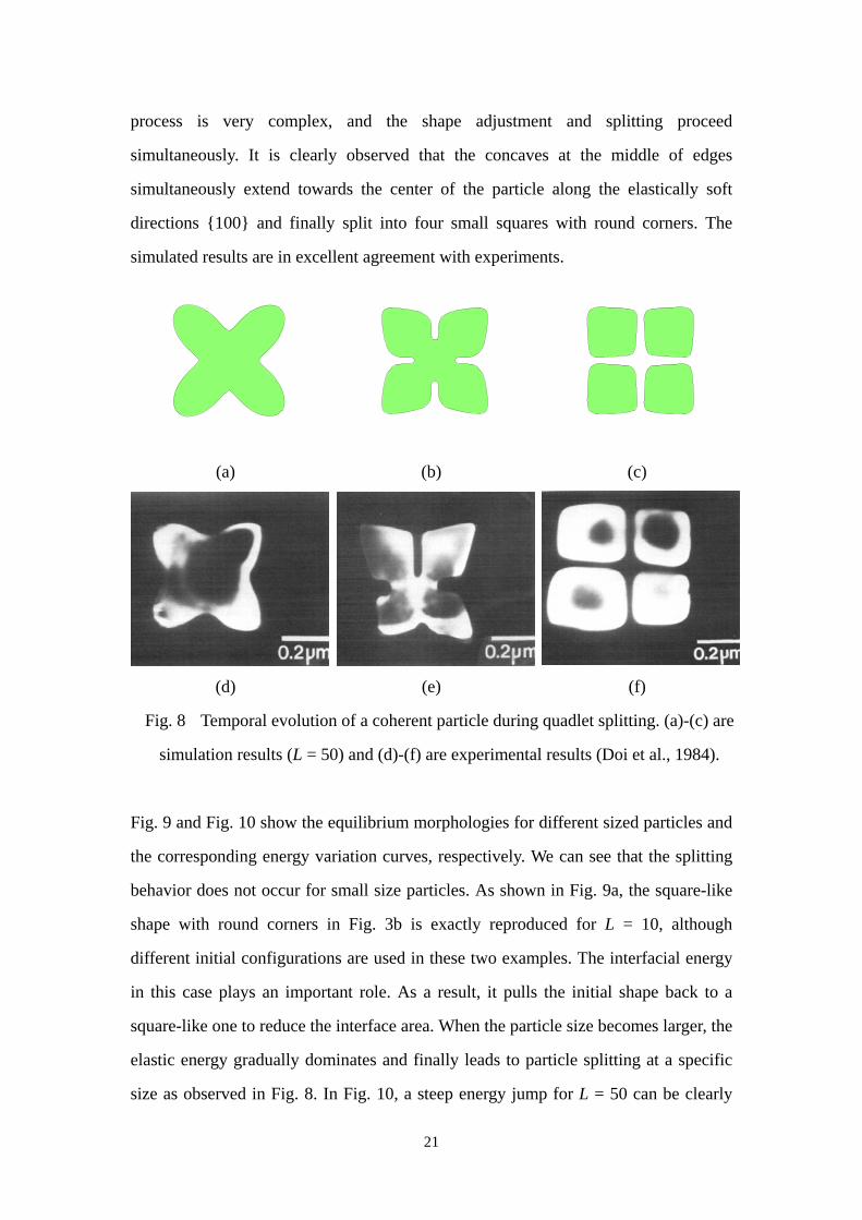
process is very complex, and the shape adjustment and splitting proceed
simultaneously. It is clearly observed that the concaves at the middle of edges
simultaneously extend towards the center of the particle along the elastically soft
directions {100} and finally split into four small squares with round corners. The
simulated results are in excellent agreement with experiments.
(a) (b) (c)
(d) (e) (f)
Fig. 8 Temporal evolution of a coherent particle during quadlet splitting. (a)-(c) are
simulation results (L = 50) and (d)-(f) are experimental results (Doi et al., 1984).
Fig. 9 and Fig. 10 show the equilibrium morphologies for different sized particles and
the corresponding energy variation curves, respectively. We can see that the splitting
behavior does not occur for small size particles. As shown in Fig. 9a, the square-like
shape with round corners in Fig. 3b is exactly reproduced for L = 10, although
different initial configurations are used in these two examples. The interfacial energy
in this case plays an important role. As a result, it pulls the initial shape back to a
square-like one to reduce the interface area. When the particle size becomes larger, the
elastic energy gradually dominates and finally leads to particle splitting at a specific
size as observed in Fig. 8. In Fig. 10, a steep energy jump for L = 50 can be clearly
21

seen during the evolution, which corresponds to the topological change (splitting) and
the total system energy is decreased approximately by 10% in this process. For the
intermediate sized particle, splitting cannot be completed as shown in Fig. 9b, because
the elastic energy in this case is not large enough to make it occur.
(a) (b) (c)
Fig. 9 Equilibrium morphologies of a four-star shaped particle at different length
scales. (a) L= 10, (b) L = 30, (c) L = 50.
0 100 200 300 400 500 6000.86
0.88
0.9
0.92
0.94
0.96
0.98
1
time step
Nor
mal
ized
tota
l ene
rgy
L = 10L = 30L = 50
Fig. 10 Energy evolution curves of a star shaped particle for different sizes.
Doublet splitting is another type of characteristic morphology observed in cubic
structured alloys. Different from the quadlet splitting above, the disordered phase
22
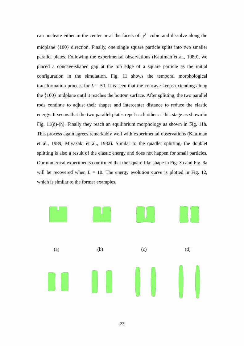
can nucleate either in the center or at the facets of cubic and dissolve along the
midplane {100} direction. Finally, one single square particle splits into two smaller
parallel plates. Following the experimental observations (Kaufman et al., 1989), we
placed a concave-shaped gap at the top edge of a square particle as the initial
configuration in the simulation. Fig. 11 shows the temporal morphological
transformation process for L = 50. It is seen that the concave keeps extending along
the {100} midplane until it reaches the bottom surface. After splitting, the two parallel
rods continue to adjust their shapes and intercenter distance to reduce the elastic
energy. It seems that the two parallel plates repel each other at this stage as shown in
Fig. 11(d)-(h). Finally they reach an equilibrium morphology as shown in Fig. 11h.
This process again agrees remarkably well with experimental observations (Kaufman
et al., 1989; Miyazaki et al., 1982). Similar to the quadlet splitting, the doublet
splitting is also a result of the elastic energy and does not happen for small particles.
Our numerical experiments confirmed that the square-like shape in Fig. 3b and Fig. 9a
will be recovered when L = 10. The energy evolution curve is plotted in Fig. 12,
which is similar to the former examples.
(a) (b) (c) (d)
23

(e) (f) (g) (h)
Fig. 11 Temporal morphological evolution in alloys that undergo a doublet splitting
(L = 50). (a)-(h) correspond to the time step 0, 50, 100, 150, 300, 500, 800 and 1200,
respectively.
0 200 400 600 800 1000 12000.88
0.9
0.92
0.94
0.96
0.98
1
time step
Nor
mal
ized
tota
l ene
rgy
Fig. 12 Energy evolution curve for a coherent particle undergoing doublet splitting
(L = 50).
7. Conclusion
In this paper, a sharp interface model has been developed to study equilibrium
morphologies of an inhomogeneity-matrix system that includes the interfacial energy
and elastic anisotropy. The driving force on the material interface is derived based on
a material derivative approach. The formulation involves using the smoothed
extended finite element to calculate the elastic field and the level set method to
describe the moving material interface. In such a framework, complex morphological
transformations of precipitate particles can be easily captured. Furthermore, the finite
element mesh is independent of the interface geometry during the evolution and no
remeshing is required, which provides great flexibility for the simulation.
24

Numerical results are carried to illustrate the striking influences of elastic energy and
interfacial energy on the equilibrium morphologies for particles of different sizes. It is
found that small particles tend to favor circle-like shape to minimize the interfacial
energy, while large particles exhibit a variety of more complex equilibrium
morphologies due to the influence of elastic energy. For multiple particles, their
elastic interaction will result in alignment of particles along certain crystallographic
directions. When the matrix nucleates at the edges of particles, misfit strain-driven
splitting may take place to reduce the total system energy. All our numerical results
are in excellent agreement with experiments. Finally, we would like to mention that
our simulation here is limited to two dimensions. Also nucleation mechanism is not
considered in the present work. Further efforts on extension to three dimensions are
being undertaken.
Acknowledgement
The work presented here was supported in part by NSF through CMMI-1200075.
Discussions with Professor David. Chopp on the implementation of the level set and
fast marching methods are gratefully acknowledged.
25

Reference
Adalsteinsson, D., Sethian, J.A., 1999. The fast construction of extension velocities in level set
methods. J Comput Phys 148, 2-22.
Ardell, A.J., 1968. An Application of Theory of Particle Coarsening - Gamma' Precipitate in Ni-Al
Alloys. Acta Metallurgica 16, 511-516.
Belytschko, T., Liu, W.K., Moran, B., 2000. Nonlinear finite elements for continua and structures. John
Wiley, Chichester ; New York.
Belytschko, T., Moes, N., Usui, S., Parimi, C., 2001. Arbitrary discontinuities in finite elements. Int J
Numer Meth Eng 50, 993-1013.
Bordas, S., Nguyen, P.V., Dunant, C., Guidoum, A., Nguyen-Dang, H., 2007. An extended finite
element library. Int J Numer Meth Eng 71, 703-732.
Cammarata, R.C., Sieradzki, K., 1994. Surface and Interface Stresses. Annu Rev Mater Sci 24,
215-234.
Chen, S., Merriman, B., Osher, S., Smereka, P., 1997. A simple level set method for solving Stefan
problems. J Comput Phys 135, 8-29.
Conley, J.G., Fine, M.E., Weertman, J.R., 1989. Effect of Lattice Disregistry Variation on the Late
Stage Phase-Transformation Behavior of Precipitates in Ni-Al-Mo Alloys. Acta Metallurgica 37,
1251-1263.
Dingreville, R., Qu, J.M., Cherkaoui, M., 2005. Surface free energy and its effect on the elastic
behavior of nano-sized particles, wires and films. J Mech Phys Solids 53, 1827-1854.
Doi, M., 1996. Elasticity effects on the microstructure of alloys containing coherent precipitates. Prog
Mater Sci 40, 79-180.
Doi, M., Miyazaki, T., Wakatsuki, T., 1984. The Effect of Elastic Interaction Energy on the
Morphology of Gamma'-Precipitates in Nickel-Based Alloys. Mater Sci Eng 67, 247-253.
Duddu, R., Bordas, S., Chopp, D., Moran, B., 2008. A combined extended finite element and level set
method for biofilm growth. Int J Numer Meth Eng 74, 848-870.
Duddu, R., Chopp, D.L., Moran, B., 2009. A Two-Dimensional Continuum Model of Biofilm Growth
Incorporating Fluid Flow and Shear Stress Based Detachment. Biotechnol Bioeng 103, 92-104.
Duddu, R., Chopp, D.L., Voorhees, P., Moran, B., 2011. Diffusional evolution of precipitates in elastic
media using the extended finite element and the level set methods. J Comput Phys 230, 1249-1264.
Eshelby, J.D., 1975. Elastic Energy-Momentum Tensor. J Elasticity 5, 321-335.
Fahrmann, M., Fratzl, P., Paris, O., Fahrmann, E., Johnson, W.C., 1995. Influence of Coherency Stress
on Microstructural Evolution in Model Ni-Al-Mo Alloys. Acta Metall Mater 43, 1007-1022.
Fahrmann, M., Hermann, W., Fahrmann, E., Boegli, A., Pollock, T.M., Sockel, H.G., 1999.
Determination of matrix and precipitate elastic constants in (gamma-gamma ') Ni-base model alloys,
and their relevance to rafting. Mat Sci Eng a-Struct 260, 212-221.
Gurtin, M.E., Murdoch, A.I., 1975. Continuum Theory of Elastic-Material Surfaces. Archive for
Rational Mechanics and Analysis 57, 291-323.
Hu, S.Y., Chen, L.Q., 2001. A phase-field model for evolving microstructures with strong elastic
inhomogeneity. Acta Mater 49, 1879-1890.
Jog, C.S., Sankarasubramanian, R., Abinandanan, T.A., 2000. Symmetry-breaking transitions in
equilibrium shapes of coherent precipitates. J Mech Phys Solids 48, 2363-2389.
Kaufman, M.J., Voorhees, P.W., Johnson, W.C., Biancaniello, F.S., 1989. An Elastically Induced
Morphological Instability of a Misfitting Precipitate. Metall Trans A 20, 2171-2175.
26

Liu, G.R., Dai, K.Y., Nguyen, T.T., 2007. A smoothed finite element method for mechanics problems.
Comput Mech 39, 859-877.
Liu, X.D., Osher, S., Chan, T., 1994. Weighted Essentially Nonoscillatory Schemes. J Comput Phys
115, 200-212.
Lou, Y., Bassani, J.L., 2008. Guided assembly of nanostructures via elastic interactions. J Mech Phys
Solids 56, 3507-3526.
Ma, Y., Ardell, A.J., 2007. Coarsening of gamma (Ni-Al solid solution) precipitates in a gamma' (Ni3Al)
matrix. Acta Mater 55, 4419-4427.
Maheshwari, A., Ardell, A.J., 1993. Morphological Evolution of Coherent Misfitting Precipitates in
Anisotropic Elastic Media. Phys Rev Lett 70, 2305-2308.
Miyazaki, T., Imamura, H., Kozakai, T., 1982. The Formation of Gamma'-Precipitate Doublets in Ni-Al
Alloys and Their Energetic Stability. Mater Sci Eng 54, 9-15.
Moës, N., Cloirec, M., Cartraud, P., Remacle, J.F., 2003. A computational approach to handle complex
microstructure geometries. Comput Method Appl M 192, 3163-3177.
Moës, N., Dolbow, J., Belytschko, T., 1999. A finite element method for crack growth without
remeshing. Int J Numer Meth Eng 46, 131-150.
Osher, S., Fedkiw, R.P., 2003. Level set methods and dynamic implicit surfaces. Springer, New York.
Osher, S., Sethian, J.A., 1988. Fronts Propagating with Curvature-Dependent Speed - Algorithms
Based on Hamilton-Jacobi Formulations. J Comput Phys 79, 12-49.
Povstenko, Y.Z., 1993. Theoretical Investigation of Phenomena Caused by Heterogeneous
Surface-Tension in Solids. J Mech Phys Solids 41, 1499-1514.
Provatas, N., Elder, K., 2010. Phase-field methods in materials science and engineering. Wiley-VCH,
Weinheim.
Schmidt, I., Gross, D., 1997. The equilibrium shape of an elastically inhomogeneous inclusion. J Mech
Phys Solids 45, 1521-1549.
Schmidt, I., Mueller, R., Gross, D., 1998. The effect of elastic inhomogeneity on equilibrium and
stability of a two particle morphology. Mech Mater 30, 181-196.
Sethian, J.A., 1996. A fast marching level set method for monotonically advancing fronts. P Natl Acad
Sci USA 93, 1591-1595.
Sethian, J.A., 1999a. Fast marching methods. Siam Rev 41, 199-235.
Sethian, J.A., 1999b. Level set methods and fast marching methods : evolving interfaces in
computational geometry, fluid mechanics, computer vision, and materials science, 2nd ed. Cambridge
University Press, Cambridge, U.K. ; New York.
Shu, C.W., Osher, S., 1988. Efficient Implementation of Essentially Non-Oscillatory Shock-Capturing
Schemes. J Comput Phys 77, 439-471.
Shuttleworth, R., 1950. The Surface Tension of Solids. P Phys Soc Lond A 63, 444-457.
Su, C.H., Voorhees, P.W., 1996. The dynamics of precipitate evolution in elastically stressed solids .1.
Inverse coarsening. Acta Mater 44, 1987-1999.
Thompson, M.E., Su, C.S., Voorhees, P.W., 1994. The Equilibrium Shape of a Misfitting Precipitate.
Acta Metall Mater 42, 2107-2122.
Tian, L., Rajapakse, R.K.N.D., 2007. Analytical solution for size-dependent elastic field of a nanoscale
circular inhomogeneity. J Appl Mech-T Asme 74, 568-574.
Voorhees, P.W., Mcfadden, G.B., Johnson, W.C., 1992. On the Morphological Development of
2nd-Phase Particles in Elastically-Stressed Solids. Acta Metall Mater 40, 2979-2992.
27

28
Wang, Y., Chen, L.Q., Khachaturyan, A.G., 1993. Kinetics of Strain-Induced Morphological
Transformation in Cubic Alloys with a Miscibility Gap. Acta Metall Mater 41, 279-296.
Zabaras, N., Ganapathysubramanian, B., Tan, L.J., 2006. Modelling dendritic solidification with melt
convection using the extended finite element method. J Comput Phys 218, 200-227.
Zhao, X.J., Bordas, S.P.A., Qu, J., 2012. A hybrid smoothed extended finite element/level set method
for modeling equilibrium shapes of nano-inhomogeneities. Submitted.