Effects of chloride and caustic on the cracking behavior ...
21
3 445b 0550859 0
Transcript of Effects of chloride and caustic on the cracking behavior ...

3 445b 0550859 0

Printed in the United States rjf Aftierica. Available from the Energy R~search and Development P,dministration,
Techriieal Information Center P.O. Box 62, Oak Ridge, Tennessee 37830
Price: Printed Copy $4.00 ; Microficiie $2.25 . .. . . . . . . . . . . . . . . . . . . . . . . . . .. .-. . . . . .. . . . . ~~. . . ~ i
This rzport was prepared as an account of work sponsored by the United States Goveriirnant Neither the United States nor the Energy Research and Dewelopment Adrninistratiun, nor any of their employres, nor any of their contractors, subcontractors, or their employees, makes any warranty, express or irnplied, or assumes any legal liability or responsibility for th. accuiacy, cornpl~?eness or ucefulnes of any information, apparatus, product or process clisclnwd, or represents that i t s use would not infringe privately owned rights

om-TM- 4 9 9 5 UC-79bb, -h, -k
(Liquid Metal F a s t Breeder Reactors)
Contract No. W-7405-eng-26
METALS AND C E W I C S DIVISION
EFFECTS OF CHLORIDE AND CAUSTIC ON THE CRACKING BEHAVIOR OF SEVERAL MATERIALS WDER ALTERNATE WET AND DRY STEAM CONDITIONS
J. C. Griess, J. P. Hammond, and W. A. Maxwell
SEPTEMBER 1975
OAK RIDGE NATIONAL TABORATORY Oak Ridge, Tennessee 37830
operated by UNION CARBIDE CORPORATION
U.S . ENERGY RESEARCH AND DEVELOPMENT ADMINISTRATION f o r the
3 q45b 0550859 0


CONTENTS
ABSTRACT . . . . . . . . . . . . . . . . . . . . . . . . . . . . . 1
INTRODUCTION . . . . . . . . . . . . . . . . . . . . . . . . . . . 1
EXPERIMENTAL PROCEDURES . . . . . . . . . . . . . . . . . . . . . 2
RESULTS . . . . . . . . . . . . . . . . . . . . . . . . . . . . . 4
Tests in Caustic Environments . . . . . . . . . . . . . . . . 4
T e s t s in Chloride Environments . . . . . . . . . . . . . . . 5
DISCUSSION . . . . . . . . . . . . . . . . . . . . . . . . . . . . 10
ACKNOWLEDGMENTS . . . . . . . . . . . . . . . . . . . . . . . . . 14


EFFECTS OF CHLORIDE AND CAUSTIC ON THE.CRACKING BEHAVIOR OF SWERAL MATERIALS UNDER ALTERNATE WET AND DRY STEAM CONDITIONS
J. C. Griess, J. P. Hammond, and W. A. Maxwell’
ABSTRACT
The s u s c e p t i b i l i t y of a number of a l l o y s t o stress- cor ros ion cracking i n steam t o which e i t h e r c h l o r i d e o r c a u s t i c has been added w a s determined. U-bend specimens were a l t e r n a t e l y exposed t o superheated steam and t o sa tu r - a t ed steam conta in ing apprec iab le moisture. Since t h e solu- b i l i t y of sodium hydroxide i n superheated steam i s extremely low under t h e test condi t ions , c a u s t i c w a s added only dur- ing t h e s a t u r a t e d steam por t ion of t h e test cyc le , and t h e maximum concent ra t ion w a s 100 ppm sodium hydroxide. A l l a l l o y s t e s t e d i n t h i s environment - inc luding low-alloy steels, types 410, 310, and 304 s t a i n l e s s steel , and high- n i c k e l a l l o y s - completely r e s i s t e d cracking. I n ch lo r ide environments e i t h e r sodium o r calcium c h l o r i d e w a s added during both t h e superheated and s a t u r a t e d p a r t of t h e cyc le (maximum concent ra t ion , 10 ppm ch lo r ide ) . The oxygen con- c e n t r a t i o n w a s 8 ppm. w e r e very s u s c e p t i b l e t o cracking. Incoloy 800 weldments i n t h e as-welded condi t ion cracked i n t h i s tes t , whi le Incoloy 800 base m e t a l and postweld hea t - t rea ted specimens d id no t . Inconel 601 and 2 114 C r - 1 Mo s teel r e s i s t e d c racking , bu t a s i n g l e crack developed i n one specimen each of Inconel 600, Inconel 625, and Has te l loy X.
Both Has te l loy N and E - B r i t e 26-1
INTRODUCTION
An important cons idera t ion i n t h e s e l e c t i o n of steam genera tor mate- r i a l s is t h e s u s c e p t i b i l i t y of candida te materials t o loca l i zed cor ros ion i n impure steam. For example, i n sodium-cooled r e a c t o r s contamination of t h e b o i l e r w a t e r and steam wi th sodium hydroxide is poss ib l e , and a know- ledge of t h e e f f e c t s produced by t h e c a u s t i c on materials i n t h e system i s requi red t o assess cor ros ion damage t h a t could occur under such f a u l t e d o r o f f - spec i f i ca t ion condi t ions . and t h e e f f e c t of t h e i r presence i n t h e system must a l s o be considered. Both c a u s t i c and c h l o r i d e ions are widely recognized as s t r e s s -co r ros ion cracking agents f o r c e r t a i n a l l o y s , and numerous i n v e s t i g a t i o n s on t h i s sub jec t are reported. However, t h e e f f e c t s of t hese two cor rodents on
Chloride ions are un ive r sa l contaminants,
Southern Nuclear Department, Nuclear U t i l i t i e s Serv ice Corporation, Clearwater, F lo r ida 33515.
1

2
var ious materials a t temperatures in te rmedia te between those oE evaporator and superhea ter o u t l e t s , where a l t e r n a t e wet t ing and of su r f aces by b o i l e r water en t ra ined i n t h e stem might occur, been widely inves t iga t ed .
t h e drying have not
The present r epor t d i scusses the e f f e c t s of ch lo r ide ions and c a u s t i c on t h e cracking behavior of p o t e n t i a l steam generator materials under alter- n a t e l y w e t and dry stearn condi t ions. Si.nce we d id no t want t o have s o l i d ch lo r ides depos i t on our specimens during t h e superheated parL of t h e test cyc le , we determined t h e s o l u b i l i t y of sodium and calcium c h l o r i d e - t h e two sal ts used i n these tests - under our test condi t ions , and these r e s u l t s are a l s o presented.
EXPERIMEHTAL PROC EDUWS
A l l t h e t e s t i n g descr ibed i n t h i s r e p o r t w a s conducted in a "once- through" loop made O C Xnconel 525. This a l l o y i s repor t ed ly very resis- tant: t o s t r e s s -co r ros ion cracking i n e i t h e r c a u s t i c o r ch lo r ide environ- men t sm7 the thermal i n s u l a t i o n . The v e r t i c a l f langed pipe (upper l e f t ) connects t o a s t e a m source discussed below. The flow ra te of t h e s t e a m i n the tests w a s 100 l b / h r (45 kg /h r ) , which corresponds t o a v e l o c i t y of about 5 f t / s e c ( 1 . 5 m/sec) pas t t h e test specimens. Contaminants w e r e added t o t h e incoming steam through a flanged connection (upper l e € t s i d e o f loop containmen& s h i e l d ) . The s t e m w a s condensed a f t e r e x i t f r o i n t h e loop and the concent ra t ion of contaminants w a s determined i n the conden- sate. The loop has two chambers o r au toc laves i n which tes t specimens can be placed (f langcd openings on e i t h e r s i d e of t h e s h i e l d ) , The i n s i d e diameter of t h e chambers i s 1.9 i n . (48 iim) and each i s 1 4 E t
Figure 1 shows t h e loop with t h e h e a t e r s i n p lace but without
( 4 . 3 m) long. The loop i s loca ted a t t h e Bartow P lan t of t h e F lo r ida Power Company,
and steam f o r t h e tests i s taken d i r e c t l y f r o m t h e main s t e a m l i ~ i e t o one of the turb ines . A t t h i s po in t , t h e temperature and pressure o f t h e s t e a m i n t h e l i n e are 5 3 8 O C ( 1 O O O O F ) and 1800 p s i ( 1 2 . 4 MPa), r e spec t ive ly , and these va lues are adjus ted t o t h e des i r ed levels before t h e s t e a m con tac t s the t es t spccimens. The loop i s operated by t h e Southern Nuclear Department of t he Nuclear U t i l i t i e s Serv ices Corporation f o r t h e Oak Ridge Nat ional Laboratory. This loop w a s f i r s t put i n t o s e r v i c e i n November 1972.
The tes t specimens w e r e U-bends with a 1/2-in. (13-nm) bend r ad ius and w e r e formed from s t r i p s 2 7/8 by 1 / 2 by 1/16 in . (73 by 1.27 by 1.6 m). Specimens designated as "ground" w e r e f i n i shed on a b e l t g r inder using 100-mesh abras ive . When welded specimens w e r e t e s t e d , t h e 1/16-in.- thick (1.6-mm) s t r i p s of t h e above s i z e were cu t from 1/2- in . - thick (13-mm) p l a t e s t h a t had mul t ipass welds ac ross t h e i r cen te r s . The welding proce- dure is descr ibed i n another paper. The welded test specimens had t h e
2Huntington A l l o y s Inconel Alloy 625, rev ised
3 J . P. Hammond, P. P a t r i a r c a , G. M. Slaughter , and W. A. Maxwell,
I n t e r n a t i o n a l Nickel Company, Inc., 1970.
"Corrosion of Incoloy 800 and Nickel Base Alloy Weldments i n Steam," VeZd. J . (Miami) 52 (6) : 268-s-280-s (June 1973).

3
'I
I ---

4
welds a t t h e apex of t h e U ' s . shown i n Fig. 2. The 1/2-in. bend r a d i u s provided an ex tens ion of about 6.2% i n t h e ou te r test sur face . The specimens w e r e arranged i n t h e loop s o t h a t t h e bottom of t h e U specimens w a s about 1 /16 i n . o f f t h e bottom of t h e au toc laves . t h e specimen w a s exposed t o w a t e r dur ing t h e s a t u r a t i o n phase of t h e test. Other d e t a i l s of t h e t e s t i n g procedure have been descr ibed previously.
Once a week t h e specimens w e r e removed from t h e loop and examined under 1 O X magni f ica t ion f o r evidence of cracks. When a crack w a s found, i ts appearance w a s noted, and marked on a sketch, and t h e specimen w a s re turned t o t h e loop un le s s complete f a i l u r e had occurred. A t t h e end of t h e tes t , a l l remaining specimens w e r e examined wi th 3 0 X magnif icat ion. Clear-cut cases of c racks were recorded, and ques t ionable ones were examined meta l lographica l ly .
The U-bends w e r e mounted i n ho lde r s as
I n t h i s p o s i t i o n t h e most h igh ly s t r a i n e d p a r t of
4
RESULTS
T e s t s i n Caus t ic Environments
Af t e r t h e Inconel 625 Loop had undergone shakedown tests t o e s t a b l i s h design condi t ions and t o check t h e i n j e c t i o n and s a f e t y systems, t h e solu- b i l i t y of sodium hydroxide i n superheated steam w a s determined under con- d i t i o n s of i n t e r e s t . Increas ing amounts of a sodium hydroxide s o l u t i o n w e r e i n j e c t e d i n t o t h e incoming s t e a m whi le t h e loop temperature and pres- s u r e w e r e he ld cons tan t a t 427OC (800'F) and 900 p s i (5.2 MPa), r e spec t ive ly . W e determined t h e concent ra t ion of c a u s t i c a t which t h e e lectr ical conduc- t i v i t y of t h e condensate from t h e e f f l u e n t ceased t o inc rease . Conductiv- i t y d i d no t i nc rease measurably wi th i n j e c t i o n rate, i n d i c a t i n g t h e solu- b i l i t y of sodium hydroxide i n s t e a m a t 427OC (800°F) and 900 p s i (6.2 MPa) i s very low. I n s o l u b i l i t y de te rmina t ions such as t h e one descr ibed he re , t h e added s o l u t e t h a t d i d no t d i s s o l v e i n t h e steam presumably deposi ted on t h e loop w a l l s .
Since t h e s e cor ros ion tests w e r e designed t o determine t h e r e s i s t a n c e of a number of a l l o y s t o s t r e s s -co r ros ion cracking under a l t e r n a t i n g w e t - d ry cond i t ions , t h e temperature of t h e loop w a s cycled between a superheat temperature and t h e s a t u r a t i o n temperature whi le t h e steam pressure w a s maintained cons tan t . For t h e test wi th c a u s t i c t h e p re s su re w a s 900 p s i (6.2 MPa) and t h e temperature w a s a l t e r n a t e d between 371 and 282OC (700 and 540'F) on a 48-hr cyc le . Sodium hydroxide w a s i n j e c t e d only during t h e s a t u r a t e d p a r t of t h e c y c l e (540OF).
i n j e c t e d i n t o t h e loop w a s p rogress ive ly increased from 2 t o 4 t o 10 ppm over a ten-week per iod , and a 12-week run w a s made wi th 100 ppm NaOH. Only dur ing t h e t i m e when 4 ppm NaOH w a s added w a s oxygen ( 4 ppm)
I n prel iminary cor ros ion tests t h e concent ra t ion of sodium hydroxide
4J. P. Hammond, P. P a t r i a r c a , G. M. S laughter , and W. A. Maxwell, Comparative Results on Chloride Stress Corrosion Cracking of Steam Generator Materials i n CycZic Steam Environments, ORNL-5031 (June 1975).

5
Y-105024
'I. W
Fig. 2. U-Bend Specimens Mounted on Holder.
introduced i n t o t h e system; a t a l l o the r t i m e s oxygen w a s he ld below t h e l i m i t of d e t e c t i o n , (less than 0.007 ppm). During t h e s e tests, welded U-bend specimens of 2 1 / 4 C r - 1 Mo steel , type 410 s t a i n l e s s steel, Incoloy 800, Inconel 625, and Has te l loy X and nonwelded U-bends of 2 1 /4 C r - 1 M o , type 304 s t a i n l e s s steel , Incoloy 800, Inconel 601, and Inconel 625 w e r e i n t h e loop. No evidence of cracking o r o the r forms of l oca l i zed a t t a c k w a s found i n any of t h e specimens.
except 50 ppm NaOH w a s i n j e c t e d during t h e s a t u r a t i o n p o r t i o n of t h e cyc le . In a d d i t i o n t o t h e a l l o y s exposed i n t h e earlier runs , U-bends of 9 C r - 1 M o s teel , s e n s i t i z e d type 304 s t a i n l e s s steel, type 304 s t a i n l e s s steel welded wi th type 308 f i l ler m e t a l , welded and unwelded Inconel 600, types 310 and 410 s t a i n l e s s steel, Has te l loy a l l o y s C, ,G, N, and S , and E - B r i t e (electron-beam-melted 26 C r - 1 Mo) were included. Specimens of t h e s e materials w e r e t e sed i n t r i p l i c a t e . and dur ing t h e e n t i r e test none of t h e specimens showed any evidence of cracking. Thus, i n a l l t h e s e c y c l i c tests wi th r e l a t i v e l y low concentra- t i o n s of c a u s t i c n o t a s i n g l e crack w a s found i n any of t h e materials t e s t ed .
An a d d i t i o n a l run, designated T e s t A , w a s made i n t h e same manner
This run l a s t e d 18 weeks,
T e s t s i n Chlor ide Environments
Only one extended c y c l i c test w a s made wi th c h l o r i d e i n t h e system, and dur ing t h i s test sodium c h l o r i d e w a s employed as t h e contaminant f o r the earlier p a r t and calcium c h l o r i d e f o r the later p a r t . T h e p re s su re and oxygen concent ra t ion w e r e he ld cons tan t a t 1625 p s i (11.2 MPa) and 8 ppm, r e spec t ive ly . between 385 and 318°C (725 and 605°F). During t h e superheat p a r t of t h e cyc le t h e ch lo r ide concent ra t ion (as NaC1) w a s maintained a t 4.2 ppm f o r t h e f i r s t 3146 h r of test and 2.7 ppm (as C a C 1 2 ) f o r t h e rest of t h e test (2960 hr). The ch lo r ide concent ra t ion during t h e sa tu ra t ed phase of t h e c y c l i c t es t w a s increased t o 10 ppm rega rd le s s of t h e sal t t h a t was used.
The temperature w a s cycled on a 48-hr per iod
6
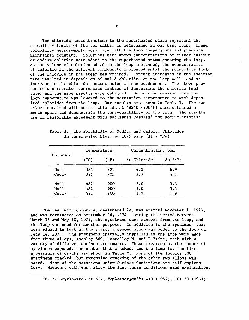
The chloride concentrations in the superheated steam represent the solubility limits of the two salts, as determined in our test loop. These solubility measurements were made with the loop temperature and pressure maintained constant. Solutions with known concentrations of either calcium or sodium chloride were added to the superheated steam entering the loop. A s the volume of solution added to the loop increased, the concentration of chloride in the effluent condensate increased until the solubility limit of the chloride in the steam was reached. Further increases in the addition rate resulted in deposition of solid chlorides on the loop walls and no increase in the chloride concentration in the condensate. The above pro- cedure was repeated decreasing instead of increasing the chloride feed rate, and the same results were obtained. Between successive runs the loop temperature was lowered to the saturation temperature to wash depos- ited chlorides from the loop. Our results are shown in Table 1. The two values obtained with sodium chloride at 482OC (900OF) were obtained a month apart and demonstrate the reproducibility of the data. The results are in reasonable agreement with published results5 for sodium chloride.
Table 1. The Solubility of Sodium and Calcium Chlorides in Superheated Steam at 1625 psig (11.2 MPa)
Temperature Concentration, ppm Chloride
("C) (OF) As Chloride As Salt
NaC 1 385 725 4.2 6.9 CaC12 385 725 2.7 4.2
NaC 1 48 2 900 2.0 3.3 NaCl 482 900 2.0 3.3 CaC12 48 2 900 1.2 1.9
The test with chloride, designated 2A, was started November 1, 1973, and was terminated on September 24, 1974. During the period between March 15 and May 10, 1974, the specimens were removed from the loop, and the loop was used for another purpose. In addition to the specimens that were placed in test at the start, a second group was added to the loop on June 14, 1974. The specimens initially installed in the loop were made from three alloys, Incoloy 800, Hastelloy N, and E-Brite, each with a variety of different surface treatments. These treatments, the number of specimens exposed, the number that cracked, and the time for the first appearance of cracks are shown in Table 2. specimens cracked, but extensive cracking of the other two alloys was noted. Most of the notations under Surface Conditions are self-explana- tory. However, with each alloy the last three conditions need explanation.
None of the Incoloy 800
'M. A. Styrkovitch et al., TepZoenerget%.a 4:3 (1957); 10: 50 (1963).

7
Table 2. U-Bend Specimens Exposed i n Test 2A of t h e Inconel 625 Loop f o r 6106 h r
Alloy Surface Condition Number of Specimens Time for
Cracked (weeks)
First Crack
Incoloy 800
Hastelloy N
E- B r i t e (26 Cr-1 Mo)
Ground Ground , annealed Electropolished Hal€ ground, half electropolished Line electropolished, surface ground Line ground, surface electropolished As above plus annealed
Ground Ground , annealed Electropolished Half ground, half electropolished Line electropolished, surface ground Line ground, surface electropolished As above plus annealed
Ground Ground , annealed Electropolished Hal€ ground, half electropolished Line electropolished, surface ground Line ground, surface electropolished As above plus annealed
0 of 3 0 of 3 0 of 3 0 of 3 0 of 3 0 of 3 0 of 3
0 of 3 3 of 3 3 of 3 0 of 3 2 of 3 3 of 3 3 of 3
2 of 3 2 of 3 3 of 3 3 of 3 3 of 3 2 of 3 3 of 3
6-8 5-9
8-12 1 1-2 5
3
14 13-14 14-1 9 11-15 5-1 1 4-1 2
11-25
I n each case a l i n e 1/16 i n . (1.6 mm) wide w a s made ac ross t h e test s t r i p so t h a t when t h e U w a s formed t h e l i n e w a s a t t h e apex. The des igna t ion
l i n e e l ec t ropo l i shed , su r f ace ground," i n d i c a t e s t h a t t h e specimen was f i r s t ground and a l l bu t t h e very narrow s t r i p w a s covered wi th masking t ape so t h a t t h e l i n e w a s formed by e l ec t ropo l i sh ing . " l i n e ground s u r f a c e e l ec t ropo l i shed , " i n d i c a t e s an i d e n t i c a l t reatment except t h a t t h e area t o become t h e l i n e w a s masked be fo re e l ec t ropo l i sh ing . Thus, t h e l i n e w a s above t h e p lane of t h e rest of t h e sur face . n o t a t i o n as t h e l a t te r followed by "annealed" means t h a t fol lowing t h e e l e c t r o p o l i s h t h e s t r i p w a s annealed be fo re forming t h e U.
of T e s t 2A and t h e r e s u l t s t h a t w e r e obtained. A t t h e end of t h e test one holder of U-bends t h a t had been i n s t a l l e d on June 14, 1974 w a s s tuck and could no t be removed. Af t e r 2828 h r of exposure i n t h e next tes t , T e s t B, t h e holder w a s f r e e d and i t w a s removed a t t h a t t i m e . The environmental condi t ions were t h e same i n T e s t B as i n 2A, and consequently Table 3 also shows t h e r e s u l t s obtained from these specimens.
A s noted i n Table 3 only t h e two E - B r i t e , t h e t h r e e as-welded Incoloy 800, one as-welded Inconel 600, one ground Has te l loy X , and one ground Inconel 625 specimens developed cracks dur ing t h e la t ter p a r t of t h e test. Only two of t h e t h r e e c racks i n t h e welded Incoloy 800 and t h e two i n E - B r i t e w e r e obvious dur ing t h e test. a t t h e end of t h e test by metallography.
11
The n o t a t i o n
The same
Table 3 shows t h e specimens t h a t were exposed during t h e l a t te r p a r t
A l l t h e o t h e r c racks w e r e found only

8
Table 3 . U-Bend Specimens Exposed f o r Only t h e Last 2169 hr of Test 2A (Except as Noted) i n t h e Inconel 625 Loop
Al loy Number of Speci-mens T i m e f o r
(weeks) S u r f a c e Condi t ion Cracked F i r s t Cracks
Incoloy 800 A s r e c e i v e d a Ground Welded w i t h Inco 82 ,
Welded w i t h I n c o 82 , anneal.edb
ground
I n c o n e l 600
I n c o n e l 601
I n c o n e l 625
H a s t e l l o y X
410 S t a i n l e s s S t e e l
E --Br i t e (26 C r - 1 Mo)
2 1 / 4 C r - 1 Mo
2 114 C r - 1 Mo-Nb
Welded w i t h Tnco 82,
Welded w i t h I n c o 82, annea ledb
ground
Ground'
AS received ' Ground
A s r e c e i v e d Ground
Welded w i t h same, annea led
Ground
d
Wel.ded w i t h same,
Welded w i t h same,
Ground, annea led Ground
ground
annea l eae
Ground, annealed
0 of 3 0 of 3 0 of 3
3 of 3
0 of 3
1 of 1
0 of 2
0 of 3 1 of 3
0 of 3 1 of 3
0 of 7.
2 of 2
0 of 3
0 of 3
0 of 3 0 of 3
0 of 2
6 1 3
1.3
30
1 3
1-2
aTwo of t h r e e specimens exposed f o r a t o t a l time of 4997 h r .
b9820C (1800°F), 1 0 min, r a p i d c o o l .
' A l l specimens exposed f o r 4997 h r .
d760°C (14OO0P), 10 min, r a p i d c o o l .
e732°C (135OoP), 1 0 m i n , r a p i d c o o l .
Figure 3 shows p a r t of a crack formed i n a welded Incoloy 800 U-bend. The crack progressed i n t e r g r a n u l a r l y through t h e large-grained heat- a f f e c t e d zone.
The only i n d i c a t i o n of a crack i n Has te l loy X w a s found under 30x magnif i c a t i m , and i t s presence w a s confirmed by metal 1 ngraphic examination. F igure 4 shows t h a t t h c crack w a s i n t e r g r a n u l a r ,

9
Y-127766
Fig. 3. Crack in a Incol Exposed During the Last 2169 hr of A i n the Inconel 6 p . 1oox.
._ :
Y-1277 72
I
Fig. 4. Crack Formed i n a Hastelloy X U-Bend During the Last 2169 hr of T e s t 2A i n the Inconel 625 Loop. 1OOX.

10
The one c rack i n t h e welded Inconel 600 specimen w a s no t apparent u n t i l t h e end of t h e test. F igure 5 shows t h e l o c a t i o n of t h e crack wi th r e fe rence t o t h e weld and a photomicrograph of t h e crack. The c rack is in t e rg ranu la r . specimen, t h e c rack appeared t o be i n t h e unaffected base m e t a l and not i n t h e hea t -a f fec ted zone.
F igure 6 (a ) is a photomicrograph of t h e as-polished su r face of t h e Inconel 625 U-bend showing t h e one c rack found during t h e later p a r t of t h e test . Note t h e s m a l l c racks emanating from t h e s i d e of t h e main c rack and t h e presence of co r ros ion products i n t h e crack. F igure 6(b) is a f u r t h e r enlargement a f t e r e t ch ing and shows t h e i n t e r g r a n u l a r na tu re of t h e crack.
I n c o n t r a s t t o t h e c rack i n t h e welded Incoloy 800
DISCUSSION
The materials used i n t h e tests descr ibed he re were subjec ted t o both e las t ic and p l a s t i c deformation. I n f a c t , t h e s t r a i n i n t h e U-bend specimens amounted t o about 6%. Furthermore, t h e r e l a x a t i o n of stresses during t h e s e tests w a s s m a l l . Based on springback of t h e U ' s t h e maximum r e l a x a t i o n w a s es t imated t o be only 10 t o 15% i n t h e ch lo r ide tests and even less i n t h e c a u s t i c tests. Thus these experiments provided a severe test of t h e s u s c e p t i b i l i t y of t h e s e materials t o s t ress -cor ros ion cracking.
Repeatedly wet t ing a s u r f a c e wi th a d i l u t e s o l u t i o n and subsequently drying i t can produce l o c a l l y high concent ra t ions of nonvo la t i l e substances on t h e dry ing sur face . By t h i s means very d i l u t e s o l u t i o n s , which may of themselves have no adverse e f f e c t on materials, can be concentrated and produce s e r i o u s l o c a l i z e d a t t a c k . The tests descr ibed i n t h i s r e p o r t w e r e conducted under such condi t ions .
s t e a m w a s so low t h a t measurable concent ra t ions could be added only when w a t e r w a s p resent i n t h e s t e a n ( sa tu ra t ed ) . Although t h e maximum concen- t r a t i o n added t o t h e steam w a s only 100 ppm, i t w a s expected t h a t as t h e temperature w a s increased from t h e s a t u r a t i o n p a r t of t h e cyc le , d r o p l e t s of t h e d i l u t e s o l u t i o n would become concentrated enough t o produce loca l i zed a t t a c k , s p e c i f i c a l l y s t r e s s -co r ros ion cracking, on most of i f no t a l l a l loys . The f a c t t h a t no c racking w a s noted i n any a l l o y is encouraging from t h e s tandpoin t of s m a l l sodium leakages i n t o t h e steam systems of sodium-cooled r e a c t o r s .
b a s i c a l l y i n agreement wi th previous da ta . Thus, nonwelded Incoloy 800 d id not crack. But as-welded specimens d id crack (Table 3) . Although none of t h e unwelded specimens of Incoloy 800 o r those t h a t w e r e welded and annealed, cracked, our r e s u l t s must no t be i n t e r p r e t e d as i n d i c a t i v e of immunity of t h i s a l l o y t o cracking. mens i n both t h e ground and ground and annealed states developed cracks
I n t h e c a u s t i c tests t h e s o l u b i l i t y of sodium hydroxide i n superheated
The r e s u l t s obtained i n t h e c h l o r i d e tests presented i n Table 2 are
Hammond6r7 showed t h a t similar speci-
6J. P. Hammond, "General Corrosion," Fuels and Materials Development Program Quurt. Progr. Rep. Sept. 30, 1971, ORNL-TM-3550, pp. 134-42.
71bid. Dee. 31, 1971, ORNL-TM-3703, pp. 142-50.

11
Y-127770
Fig. 5 . Crack Formed i n a Welded Inconel 600 U-Bend During the Last 2169 hr of T e s t 2A in the Inconel 625 Loop. (a) 12.5x. (b) Etched. 1OOX.

12
I
.
. . , I (
I. . . ...
4
. , . ..
. .
. -
. .- I.
Fig. 6. The One Crack Pound i n an Inconel 625 U-Bend Specimen Exposed f o r 2169 h r i n T e s t 2A and 2828 h r i n Test B. 1 0 0 ~ . (b) End of t h e crack after e tch ing , 2 5 0 ~ .
(a ) As pol i shed ,

13
i n c y c l i c tests wi th 10 ppm c h l o r i d e and 20 ppm 0 2 . ronment he a l s o showed t h a t some specimens welded wi th Inconel 82 f i l l e r m e t a l and exposed both as welded and as postweld annealed cracked. i n agreement wi th our r e s u l t s , welded specimens t h a t had been annealed w e r e less s u s c e p t i b l e t o cracking than those t h a t were t e s t e d as welded.
Also, E - B r i t e had been shown t o be very s u s c e p t i b l e t o chlor ide- induced cracking i n high-temperature steam8 ,' and t h e present tests ind i - cate t h a t t h i s s u s c e p t i b i l i t y i s e s s e n t i a l l y independent of su r f ace condi- t i o n . r e s i s t a n c e t o both p i t t i n g and cracking i n c h l o r i d e environments, bu t i n our tests i ts r e s i s t a n c e t o c racking w a s extremely low.
The very h igh inc idence of cracking i n Haste'lloy N w a s expected i n view of previous experience. 6 ' 7 Why cracking w a s no t observed i n any of t h e t h r e e ground specimens o r i n t h e t h r e e h a l f ground and h a l f e l e c t r o - pol ished specimens i s not understood. I n t h e above referenced tests, specimens wi th t o t a l l y ground s u r f a c e s cracked, and i n t h e present test t h e t o t a l l y e l ec t ropo l i shed specimens f a i l e d .
Both Inconel 601 and Inconel 625 are h ighly r e s i s t a n t t o ch lor ide- induced cracking. A l a r g e number of tests wi th t h e s e two a l l o y s has been completed i n o t h e r p a r t s of t h e test program (not included i n t h i s r e p o r t ) , and t h e only c rack found i n e i t h e r a l l o y w a s t h e s m a l l c rack shown i n Fig. 6 . Furthermore, no f a i l u r e s have been found i n t h e Inconel 625 loop, which has been i n use wi th chlor ide-containing s t e a m f o r about one year . Continued opera t ion of t h i s loop i n ch lo r ide environments i s planned; bu t , when decommissioned, it w i l l be thoroughly examined f o r evidence of co r ros ion damage.
A s expected, 2 1 / 4 C r - 1 Mo s teel showed no tendency t o c rack i n t h e oxygenated c h l o r i d e environment. However, i t s r e s i s t a n c e t o gene ra l cor ros ion w a s poor. The U-bend specimens w e r e covered wi th heavy scale, much of which w a s e a s i l y removed by g e n t l e tapping of t h e specimen. It should be pointed ou t , however, t h a t t h e condi t ions used i n t h i s test w e r e no t t y p i c a l o f - t h o s e t h a t could e x i s t f o r any extended t i m e i n a r e a c t o r steam system, bu t r a t h e r w e r e chosen t o determine t h e degree of r e s i s t a n c e of a number of a l l o y s t o chloride-induced cracking. The h igh gene ra l o r uniform cor ros ion experienced by 2 1 / 4 C r - 1 Mo s t ee l i n t h e s e tests, t h e r e f o r e , i n no way compromises i t s use i n t h e superhea ter and evaporator of t h e steam genera tor i n t h e Clinch River Breeder Reactor. The r e s i s t a n c e of t h i s a l l o y t o cracking i n t h e presence of c h l o r i d e as w e l l as i ts demonstrated r e s i s t a n c e t o cracking i n c a u s t i c environments, both i n our tests and those of Indig," means t h a t f a i l u r e of t h e steam
In t h e same envi-
However,
A t much lower temperatures t h i s a l l o y has a very h igh degree of
8J. P. Hammond and G. M. S laughter , "Corrosion of Advanced Steam Generator Alloys," Metals and Ceramics Div. Annu. Progr. Rep. June 30, 1972, ORNL-4820, pp. 42-46.
9J. p. Hammond and w. A. Maxwell, "Flor ida Loop Program on General and S t r e s s Corrosion Cracking of Steam Generator Alloys, ' ' Fuels and Materials Development Program Quart. Progr. Rep. Sept. 30, 1972, ORNL-TM-4055, pp. 212-2.12.
'El. E. Ind ig , Stress Corrosion Studies of LMFBR Steam Gmerator Materials, GW-12536 (August 1974).

44
system i n t h e Clinch River Breeder Reactor by a s t ress -cor ros ion cracking mode is extremely remote.
A s i nd ica t ed earlier, t h e stress levels i n t h e specimens used i n t h e s e tests w e r e very high ( 6 . 2 % t o t a l s t r a i n wi th l i t t l e thermal re laxa- t i o n of stresses). When cracking occurred, i t usua l ly o r ig ina t ed i n p l a s t i c a l l y deformed su r faces . Other tests i n ch lo r ide environments wi th many of t h e same a l l o y s are now being conducted wi th a specimen design f o r which a cons tan t stress e x i s t s i n t h e test sec t ion . The stresses being inves t iga t ed are i n t h e range of des ign stresses, and fewer c racks are t o be expected. The r e s u l t s of those tests w i l l be repor ted later.
ACKNOWLEDGMENTS
The au thors wish t o express t h e i r apprec ia t ion t o t h e personnel of t h e Bartow P lan t of t h e F lo r ida Fower Corporation f o r t h e i r support and cooperat ion i n conducting t h e s e experiments and t o Sco t t Theiss of t h e NUS Corporation f o r examining t h e specimens during t h e course of t h e tests. The metal lographic examinations f o r t h i s r e p o r t were prepared by C. E. Zachary of ORNL. The r epor t w a s ed i t ed by Sigf red Peterson and typed and prepared f o r reproduct ion by Regina Co l l in s .
I
b

O W - T M - 4 9 95 UC-79b, -h, -k
(Liquid Metal Fas t Breeder Reactors)
INTERNAL DISTRIBUTION
(3) Cent ra l Research Library ORNL - Y-12 Technical Library
Document Reference Sec t ion (10) Laboratory Records Department
Laboratory Records, ORNL RC ORNL Pa ten t Of f i ce G. M. Adamson, Jr. M. Bender C. R. Brinkman D. A. Canonico W. B. C o t t r e l l F. L. Cu l l e r J. E. Cunningham J. H. DeVan J. R. DiStefano R. G. Donnelly G. M. Goodwin
(5) J. P . Harmnond
(3) M. R. H i l l
(10) J , C. Griess, Jr.
W. 0. Harms
R. L. Heestand Y. R. Kasten A. L. L o t t s T. S. Lundy W. R. Mart in R. W. McClung H. E. McCoy P. P a t r i a r c a P. L. Ri t tenhouse T. K. Roche J. E. S e l l e G. M. Slaughter D. B. Trauger J. R. Weir, Jr. W. C. L e s l i e (consul tan t ) John Moteff (consul tan t ) Hayne Palmour I11 (consul tan t ) J. W. Prados (Consul tant) N. E. Promise1 (consul tan t ) G. V. Smith (consul tan t ) D. F. S t e i n (consul tan t )
EXTERNAL DISTRIBUTION
USERDA DIVISION OF REACTOR'RESEARCH AND DEVELOPMENT, Washington, DC 20545
( 2 ) Di rec tor
USERDA OAK RIDGE OPERATIONS OFFICE, P.O. Box E , Oak Ridge, TN 37830
Direc to r , Reactor Div is ion Research and Technical Support Div is ion
USERDA TECHNICAL INFORMATION CENTER, Of f i ce of Information Serv ices , P.O. Box 62, Oak Ridge, TN 37830
(309) For d i s t r i b u t i o n as shown i n TID-4500 D i s t r i b u t i o n Category, UC-79b (Fuels and Materials Engineering Development); UC-79h ( S t r u c t u r a l Materials and Design Engineer ing); UC-79k (Components)