
Effects of Bearing Configuration in wind Turbine...
10
General rights Copyright and moral rights for the publications made accessible in the public portal are retained by the authors and/or other copyright owners and it is a condition of accessing publications that users recognise and abide by the legal requirements associated with these rights. • Users may download and print one copy of any publication from the public portal for the purpose of private study or research. • You may not further distribute the material or use it for any profit-making activity or commercial gain • You may freely distribute the URL identifying the publication in the public portal If you believe that this document breaches copyright please contact us providing details, and we will remove access to the work immediately and investigate your claim. Downloaded from orbit.dtu.dk on: Jun 23, 2018 Effects of bearing configuration in wind turbine gearbox reliability Gallego Calderon, Juan Felipe; Natarajan, Anand; Dimitrov, Nikolay Krasimirov Published in: Energy Procedia Link to article, DOI: 10.1016/j.egypro.2015.11.443 Publication date: 2015 Document Version Publisher's PDF, also known as Version of record Link back to DTU Orbit Citation (APA): Gallego Calderon, J. F., Natarajan, A., & Dimitrov, N. K. (2015). Effects of bearing configuration in wind turbine gearbox reliability. Energy Procedia, 80, 392–400. DOI: 10.1016/j.egypro.2015.11.443
Transcript of Effects of Bearing Configuration in wind Turbine...

General rights Copyright and moral rights for the publications made accessible in the public portal are retained by the authors and/or other copyright owners and it is a condition of accessing publications that users recognise and abide by the legal requirements associated with these rights.
• Users may download and print one copy of any publication from the public portal for the purpose of private study or research. • You may not further distribute the material or use it for any profit-making activity or commercial gain • You may freely distribute the URL identifying the publication in the public portal
If you believe that this document breaches copyright please contact us providing details, and we will remove access to the work immediately and investigate your claim.
Downloaded from orbit.dtu.dk on: Jun 23, 2018
Effects of bearing configuration in wind turbine gearbox reliability
Gallego Calderon, Juan Felipe; Natarajan, Anand; Dimitrov, Nikolay Krasimirov
Published in:Energy Procedia
Link to article, DOI:10.1016/j.egypro.2015.11.443
Publication date:2015
Document VersionPublisher's PDF, also known as Version of record
Link back to DTU Orbit
Citation (APA):Gallego Calderon, J. F., Natarajan, A., & Dimitrov, N. K. (2015). Effects of bearing configuration in wind turbinegearbox reliability. Energy Procedia, 80, 392–400. DOI: 10.1016/j.egypro.2015.11.443

1876-6102 © 2015 The Authors. Published by Elsevier Ltd. This is an open access article under the CC BY-NC-ND license (http://creativecommons.org/licenses/by-nc-nd/4.0/).Peer-review under responsibility of SINTEF Energi ASdoi: 10.1016/j.egypro.2015.11.443
Energy Procedia 80 ( 2015 ) 392 – 400
ScienceDirect
12th Deep Sea Offshore Wind R&D Conference, EERA DeepWind'2015
Effects of bearing configuration in wind turbine gearbox reliability
Juan Gallego-Calderon*, Anand Natarajan, Nikolay K. Dimitrov
Technical University of Denmark, DTU Wind Energy, DTU Risø Campus, Frederiksborgvej 399, 4000 Roskilde, Denmark
Abstract
This paper investigates the impact on the reliability of different configurations of planet bearings. The studied bearings are located in the low-speed planetary stage of a wind turbine gearbox. The bearing stiffness matrix for each kind, cylindrical and tapered roller bearing (CRB and TRB), is included in the electro-mechanical drive-train simulation tool presented here. The system defined in Matlab/Simulink is co-simulated along with a wind turbine defined in an aeroelastic software. Moreover, the normal production design load case (DLC 1.1) is used to compute the bearing response to different turbulence seeds. From this, the fatigue and reliability of the bearings is calculated using the damage equivalent load and the first-order reliability method (FORM), where the L10h life is used as a limit state. The results indicate a relation between the reliability index and the bearing dynamic rating. However, when the actual parameters from the manufacturer are used, the TRB shows higher reliability even though its damage equivalent load is higher across the wind speed range. © 2015 The Authors. Published by Elsevier Ltd. Selection and peer-review under responsibility of SINTEF Energi AS.
Keywords: bearings; reliability; wind turbine gearbox; electro-mechanical model
1. Introduction
One of the main focuses of the wind energy research community is to design systems based not simply on dynamical models representing the behavior of the system, but on models that also include stochastic information. The latter approach allows an estimation of the expected lifetime (or expected failure frequency) of the components based on previous knowledge of the wind conditions, strength of the material, to name a few. A big element of this
* Corresponding author. Tel.: +45 21121623.
E-mail address: [email protected]
Available online at www.sciencedirect.com
© 2015 The Authors. Published by Elsevier Ltd. This is an open access article under the CC BY-NC-ND license (http://creativecommons.org/licenses/by-nc-nd/4.0/).Peer-review under responsibility of SINTEF Energi AS
Juan Gallego-Calderon et al. / Energy Procedia 80 ( 2015 ) 392 – 400 393
approach is to make reliability based decisions in order to minimize costs in repair and maintenance of wind turbine components.
In the context of wind turbine drive-trains, it is of high relevance to study the planetary stage bearings due to the recurrent failures that reduce the lifetime of the components and end up in downtime. Therefore, it is important to consider different configurations in the design stage of the gearbox. For instance, different types of bearings are designed to withstand different loading distributions among the rollers. In this paper, a bearing model presented by [1] is implemented in an electro-mechanical simulation model of the drivetrain. The model is able to estimate the bearing stiffness matrix components in the radial directions given the bearing physical parameters such as race dimensions, number of rollers and roller contact angle.
In the past, other studies have focused on the fatigue of the planetary bearings. For example, Nejad et al. [2] presented results for the entire gearbox components in terms of the cumulative damage and produced a “vulnerability map” where it is possible to identify the components more prone to failure. Other study found, from field data, that failure due to bearing fatigue is feasible even at rated conditions given their observations of the bearing loads in the planetary stage [3]. According to the study, some events that produce torques above 150% of rated could induce higher damage in the components. This is the case in extreme events such as emergency brakes or electric faults. However, these are cases that do not occur that often so there is a need to analyze normal operation conditions when focusing on fatigue and reliability only.
The paper is structured as: first, the simulation tools are described, along with the co-simulation approach where the wind turbine structural model interacts with the externally defined drive-train. Then, the gearbox model is briefly described, followed by an explanation of the bearing model: cylindrical roller bearing (CRB) and tapered roller bearing (TRB). The difference in the model lies in the contact angle of the rollers and the effect it has on the stiffness matrix. Later, the reliability analysis is done in conjunction to the bearing life and the requirements of the IEC 61400-1 Ed.3 standard for wind turbine design [4]. Finally, the results are explained and conclusions are drawn from the difference in terms of reliability found between the two bearing models.
2. Methods and models
2.1. Simulation tools
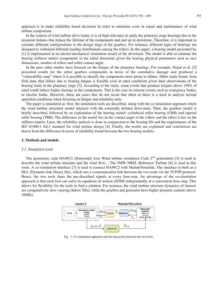
The aeroelastic code HAWC2 (Horizontal Axis Wind turbine simulation Code 2nd generation) [5] is used to describe the wind turbine structure and the wind flow. , The 5MW NREL Reference Turbine [6] is used in this work. A co-simulation interface [7] is used to connect HAWC2 with Matlab/Simulink. The interface is built as a DLL (Dynamic-link library file), which sets a communication link between the two tools via the TCP/IP protocol. Hence, the two tools share the pre-described signals at every time-step. An advantage of the co-simulation approach is that each tool can solve its equations of motion (EOM) independently at a convenient time-step. This allows for flexibility for the tools to find a solution. For instance, the wind turbine structure dynamics of interest are comparatively slow-varying (below 5Hz), while the gearbox and generator have higher dynamic content (above 100Hz).
Fig. 1. Co-simulation approach and the interaction between the two tools.

394 Juan Gallego-Calderon et al. / Energy Procedia 80 ( 2015 ) 392 – 400
In this simulation setup, the two systems are coupled by the torsional degree of freedom of the main shaft, therefore, non-torque loads in the rotor are not considered in the analysis. The coupler block diagram estimates the rotor torsion at the input of the drive-train in order to be applied to the gearbox and as a reaction to the main shaft and tower-top of the wind turbine. Since there is a dynamic coupling, any changes in the equilibrium of the EOM in Matlab will have effects in the wind turbine structure. Hence, this approach provides a system where the effects of the generator torque influence the gearbox and the wind turbine structure. A more comprehensive description is of the interaction between the two tools and the validation of the simulation is presented in [8].
2.2. Drive-train model
The gearbox is represented by a translational/rotational model and follows the formulation presented in [9]. The model presented is a three-stage gearbox with a planetary stage as the low-speed stage and two parallel stages as the intermediate and high speed (ISS and HSS), respectively. The description of the coordinates of the planetary stage is presented in Fig. 2. Each gear-wheel is represented by a rigid body and the interactions due to the gear teeth flexibility are described by a linear spring whose stiffness represents the gear mesh stiffness of the gear pairs approximately. Thus, the bearings are modeled as linear springs and act as flexible supports for the planets, sun, gears and pinions throughout the gearbox. The coupling between each stage is done by a torsional spring between the input and output gear wheel rotational degree-of-freedom from the connecting stages.
Fig. 2. Gearbox model and its coordinate system (left); Roller bearing (cylindrical or tapered) coordinate system and kinematics. The forces and moments are included for illustration purposes and to define their direction. The z direction goes out of the plane (modified from [1])
In addition, the generator inertia is coupled via torsion with the pinion of the HSS. The equations of motion
regarding the mechanical model are arranged in a state-space model and the solution is found by numerical integration using a standard ODE solver from Matlab/Simulink [10].
The generator used here is a permanent magnet synchronous generator (PMSG) and it uses the parameters from [11]. A model used in wind turbine with PMSG studies [12] is implemented in Simulink. The input to the model is the generator inertia speed and the output is the electromagnetic torque. The latter is used as an input to the gearbox model. The machine controller compensates the generator torque using as a reference the torque demand calculated by the baseline wind turbine controller [13] (see signal in Fig. 1). A correct control ensures a dynamic response of the HSS, is in equilibrium with the EOM from both tools.
2.3. Bearing model
It is usual to represent the bearings as a linear stiffness in the radial directions [14]–[16]. This representation is useful for a modal analysis of the dynamics of the system [14] and to study the lateral vibrations of a rotor system.
Juan Gallego-Calderon et al. / Energy Procedia 80 ( 2015 ) 392 – 400 395
The theory of bearing design [18] and dynamic modelling of bearing elements is well documented in literature, where several authors propose different methods to find the stiffness matrices and the bearing loads. These models are a function of the bearing geometry, contact deformation, and the effective axial and radial displacements of the bearing's center of gravity, according to Hertzian contact theory. In [1], the authors present the models for ball and cylindrical roller bearings with special attention to the development of the stiffness matrix which shows the effects of the cross-coupling components in the overall dynamic response. Their main contribution is a model that can be used to study the vibration transmission across rolling element bearings due to the wind turbine rotor dynamics.
This section presents the method implemented in order to find the cross-terms of the bearing stiffness matrices and the bearing forces acting on the shaft and gear bodies. The main objective is to study the impact on the bearing loads under different conditions. The method is the same as presented by [1] but it is documented in this section as background information to illustrate the effect on the bearing loads given the mean bearing displacements and radial clearance for a roller bearing.
The elastic deformation of a roller bearing is determined by
0,0
0,sincos 00
R
RzjrjjR (1)
where rj and zj correspond to the effective radial and axial displacements of the thj rolling element, respectively and are defined in equations (2) and (3); and is the unloaded contact angle. For the rolling bearing type 0 is constant because it is not affected by the loading and the elastic deformation of the rolling elements. In this paper, cylindrical roller bearings are treated with and tapered roller bearings .
)cos()sin()( jzmjxmjzzj r (2)
Ljymjxmrj r)sin()cos()( (3)
where , , , , are the inner raceway displacements in the , and z directions, and the tilting motion in the and directions, respectively as seen in; and is the rolling element position. The elastic deformations for each roller are used to calculate the bearing stiffness terms [1], and consequently the bearing stiffness matrix (4) for specific displacements and tilting in the and . These deflections correspond to the lateral vibrations of the shaft, and consequently, the planetary gear. The model described is used to determine the stiffness in the radial direction given that the model considers only translations in the x-y plane, in addition to rotation. It is possible to find the 6x6 matrix for a full 3D model, but this is not considered in this paper.
000
0
0
yyxy
xyxx
b KK
KK
K (4)
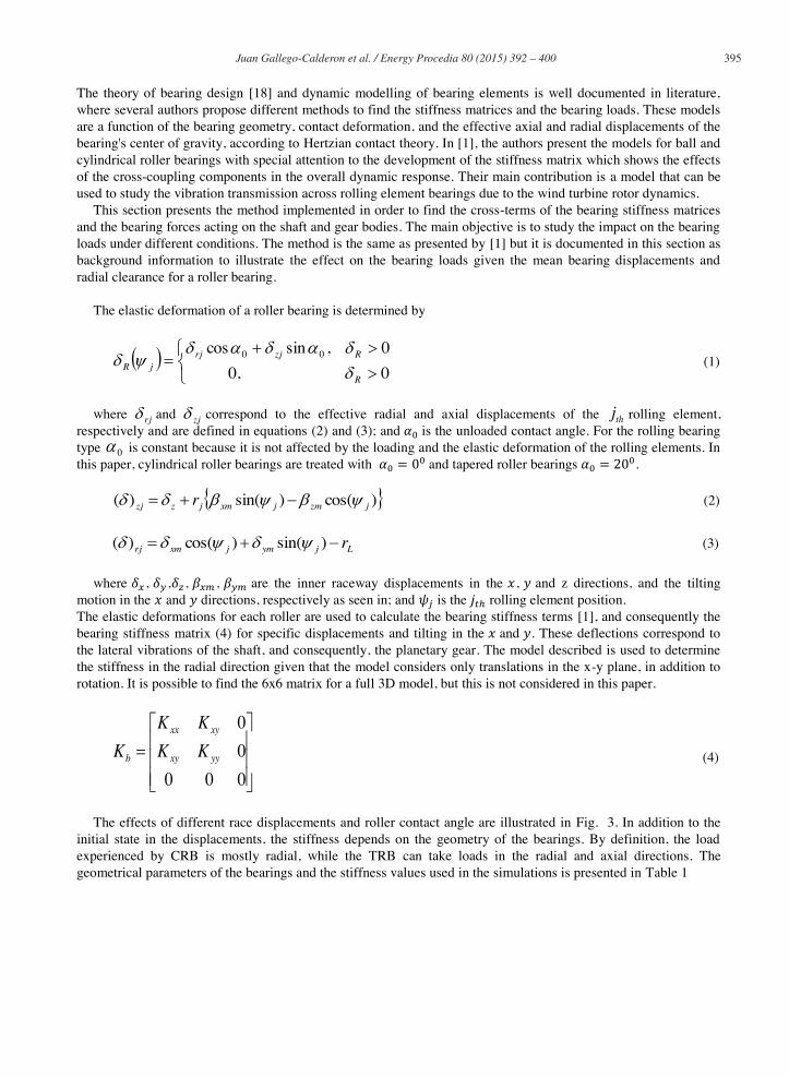
The effects of different race displacements and roller contact angle are illustrated in Fig. 3. In addition to the initial state in the displacements, the stiffness depends on the geometry of the bearings. By definition, the load experienced by CRB is mostly radial, while the TRB can take loads in the radial and axial directions. The geometrical parameters of the bearings and the stiffness values used in the simulations is presented in Table 1
396 Juan Gallego-Calderon et al. / Energy Procedia 80 ( 2015 ) 392 – 400
Table 1. Bearing stiffness parameters for the CRB and TRB.
Type of Bearing [N/m] [N/m]
Cylindrical Roller Bearing
Tapered Roller Bearing
Fig. 3. Bearing stiffness component variation due to different values of displacement in the x direction and contact angle.
3. Simulation Results
The entire wind turbine system is simulated using the co-simulation approach presented in the previous section. Two sets of simulations are done, each with a different bearing stiffness matrix representing the difference in bearing configuration. The DLC 1.1 normal operation case from the IEC 61400-1 ed. 3 standard [4] is chosen in order to perform fatigue computations and reliability analysis from both configurations. In total, six random turbulence seeds using the NTM (Normal Turbulence Model) are simulated at mean wind speeds ranging from 5 m/s to 25 m/s in increments of 2 m/s bins.
3.1. Bearing life
The time-series is analyzed to compute the bearing fatigue damage resulting from variations in the torsional loads due to turbulent wind. Furthermore, the reactions due to the gear mesh forces also have an effect in the bearing response. The analysis in this section uses the loads in units of Newton opposed to stresses which are commonly used in this type of analysis. The damage equivalent load due to the bearing radial forces is found by:
mN
i
mii
eq
b
N
SnS
/1
1
(5)
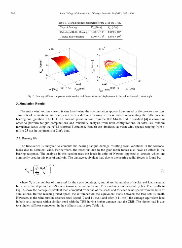
where Nb is the number of bins used for the cycle counting, ni and Si are the number of cycles and load range at bin i, m is the slope in the S-N curve (assumed equal to 3) and N is a reference number of cycles. The results in Fig. 6 show the damage equivalent load computed from one of the seeds and for each wind speed from the bulk of simulations. Before reaching rated speed the difference on the equivalent loads between the two sets is small. However, as the wind turbine reaches rated-speed (9 and 11 m/s), and after (>11 m/s), the damage equivalent load in both sets increase with a similar trend with the TRB having higher damage than the CRB. The higher load is due to a higher stiffness component in the stiffness matrix (see Table 1).
0
0.02
0.04
0
50
0
5
10
x 108
xm [mm] [Deg]
Kxx
[N
/mm
]
0
0.02
0.04 0
50
0
1
2
x 106
[Deg]xm [mm]
Kxy
[N
/mm
]
Juan Gallego-Calderon et al. / Energy Procedia 80 ( 2015 ) 392 – 400 397
The main focus is to determine whether a CRB or a TRB configuration is more beneficial for the planetary gearbox reliability. Hence, the minimum requirements for a wind turbine’s bearing life given by [19] are used for the analysis of these configurations. The basic rating life can be computed using:
p
h P
C
nL
60
106
10 (6)
where n is the operational speed, C is the bearing dynamic load rating (given by the manufacturer), P is the equivalent load and p is the life exponent (10/3 for roller bearings). According to the IEC 61400-4 standard [19], the recommended basic rating life for a bearing in the low-speed planetary stage should be of 105 hours for a 20 year design life.
Fig. 4. 1-h Damage equivalent load of one of the seeds for both sets of simulation.
3.2. Reliability
The main purpose of reliability analysis is to find the probability of failure of a given structure subjected to loading. For the computation of reliability it is necessary to specify the resistance of the structure, along with different uncertainties related to the application. The basic problem formulation in reliability analysis is to define the so-called limit state equation , which describes the state of the structure by a quantitative index [20], [21]. Normally, indicates failure. Calculating the probability of failure amounts to evaluating the integral of the joint distribution of the set of random variables over the failure domain:
(7)
where is the probability density function of the random variables x. These variables are representative of the loading in the structure, the resistance and the associated uncertainties, and is a zero-one indicator function which equals 1 when . Because the analysis of the bearing life is of interest in this study, the limit state function is formulated as:
56
10)(60
10)(
p
statdynaerorP
C
nxg
x (8)
where , , and are stochastic variables representing the uncertainties in: aerodynamic load calculation, dynamic response of the turbine, and statistical uncertainty due to the reduced number of simulations.
0 5 10 15 20 25 300.5
1
1.5
2
2.5x 10
5
Wind Speed [m/s]
Dam
age
Equ
ival
ent L
oad
[N]
CRB
TRB
398 Juan Gallego-Calderon et al. / Energy Procedia 80 ( 2015 ) 392 – 400
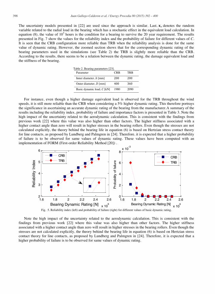
The uncertainty models presented in [22] are used since the approach is similar. Last, denotes the random variable related to the radial load in the bearing which has a stochastic effect in the equivalent load calculation. In equation (8), the value of 105 hours is the condition for a bearing to survive the 20 year requirement. The results presented in Fig. 7 show the values for the reliability index and the probability of failure for different values of C. It is seen that the CRB configuration more reliable than TRB when the reliability analysis is done for the same value of dynamic rating. However, the zoomed section shows that for the corresponding dynamic rating of the bearing parameters used in the simulations (see Table 2) the TRB is slightly more reliable than the CRB. According to the results, there seems to be a relation between the dynamic rating, the damage equivalent load and the stiffness of the bearing.
Table 2. Bearing parameters [23]. Parameter CRB TRB
Inner diameter, [mm]
Outer diameter, [mm]
Basic dynamic load, [kN] 1980 2090
For instance, even though a higher damage equivalent load is observed for the TRB throughout the wind
speeds, it is still more reliable than the CRB when considering a 5% higher dynamic rating. This therefore portrays the significance in ascertaining an accurate dynamic rating of the bearing from the manufacturer.A summary of the results including the reliability index, probability of failure and importance factors is presented in Table 3. Note the high impact of the uncertainty related to the aerodynamic calculation. This is consistent with the findings from previous work [22] where this value was also higher than other factors. The higher stiffness associated with a higher contact angle than zero will result in higher stresses in the bearing rollers. Even though the stresses are not calculated explicitly, the theory behind the bearing life in equation (6) is based on Hertzian stress contact theory for line contacts, as proposed by Lundberg and Palmgren in [24]. Therefore, it is expected that a higher probability of failure is to be observed for same values of dynamic rating. These values have been computed with an implementation of FORM (First-order Reliability Method [20]) .
Fig. 5. Reliability index (left) and probability of failure (right) for different values of basic dynamic rating.
Note the high impact of the uncertainty related to the aerodynamic calculation. This is consistent with the findings from previous work [22] where this value was also higher than other factors. The higher stiffness associated with a higher contact angle than zero will result in higher stresses in the bearing rollers. Even though the stresses are not calculated explicitly, the theory behind the bearing life in equation (6) is based on Hertzian stress contact theory for line contacts, as proposed by Lundberg and Palmgren in [24]. Therefore, it is expected that a higher probability of failure is to be observed for same values of dynamic rating.
1.6 1.8 2 2.2 2.4 2.6
x 106
2
3
4
5
6
Bearing Dynamic Rating [N]
Rel
iabi
lity
Inde
x
CRB
TRB
1.6 1.8 2 2.2 2.4 2.6
x 106
0
2
4
6
8x 10
-3
Bearing Dynamic Rating [N]
Pro
babi
lity
of fa
ilure
CRB
TRB
Juan Gallego-Calderon et al. / Energy Procedia 80 ( 2015 ) 392 – 400 399
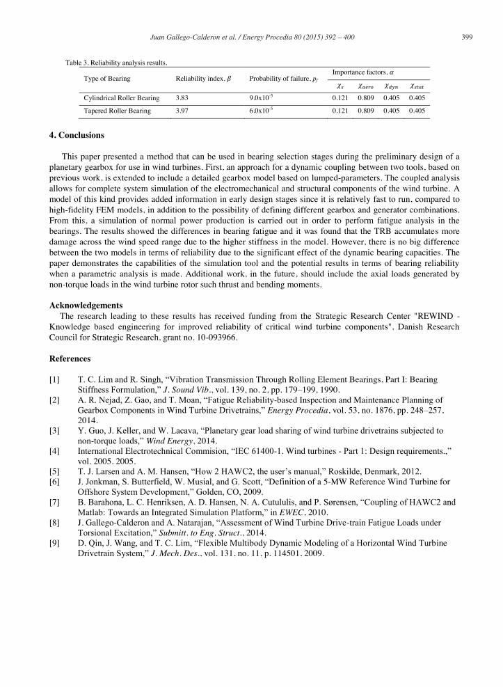
Table 3. Reliability analysis results.
Type of Bearing Reliability index, Probability of failure, pf
Importance factors,
Cylindrical Roller Bearing 3.83 9.0x10⁻⁵ 0.121 0.809 0.405 0.405
Tapered Roller Bearing 3.97 6.0x10⁻⁵ 0.121 0.809 0.405 0.405
4. Conclusions
This paper presented a method that can be used in bearing selection stages during the preliminary design of a planetary gearbox for use in wind turbines. First, an approach for a dynamic coupling between two tools, based on previous work, is extended to include a detailed gearbox model based on lumped-parameters. The coupled analysis allows for complete system simulation of the electromechanical and structural components of the wind turbine. A model of this kind provides added information in early design stages since it is relatively fast to run, compared to high-fidelity FEM models, in addition to the possibility of defining different gearbox and generator combinations. From this, a simulation of normal power production is carried out in order to perform fatigue analysis in the bearings. The results showed the differences in bearing fatigue and it was found that the TRB accumulates more damage across the wind speed range due to the higher stiffness in the model. However, there is no big difference between the two models in terms of reliability due to the significant effect of the dynamic bearing capacities. The paper demonstrates the capabilities of the simulation tool and the potential results in terms of bearing reliability when a parametric analysis is made. Additional work, in the future, should include the axial loads generated by non-torque loads in the wind turbine rotor such thrust and bending moments. Acknowledgements
The research leading to these results has received funding from the Strategic Research Center "REWIND - Knowledge based engineering for improved reliability of critical wind turbine components", Danish Research Council for Strategic Research, grant no. 10-093966.
References
[1] T. C. Lim and R. Singh, “Vibration Transmission Through Rolling Element Bearings, Part I: Bearing Stiffness Formulation,” J. Sound Vib., vol. 139, no. 2, pp. 179–199, 1990.
[2] A. R. Nejad, Z. Gao, and T. Moan, “Fatigue Reliability-based Inspection and Maintenance Planning of Gearbox Components in Wind Turbine Drivetrains,” Energy Procedia, vol. 53, no. 1876, pp. 248–257, 2014.
[3] Y. Guo, J. Keller, and W. Lacava, “Planetary gear load sharing of wind turbine drivetrains subjected to non-torque loads,” Wind Energy, 2014.
[4] International Electrotechnical Commision, “IEC 61400-1. Wind turbines - Part 1: Design requirements.,” vol. 2005. 2005.
[5] T. J. Larsen and A. M. Hansen, “How 2 HAWC2, the user’s manual,” Roskilde, Denmark, 2012. [6] J. Jonkman, S. Butterfield, W. Musial, and G. Scott, “Definition of a 5-MW Reference Wind Turbine for
Offshore System Development,” Golden, CO, 2009. [7] B. Barahona, L. C. Henriksen, A. D. Hansen, N. A. Cutululis, and P. Sørensen, “Coupling of HAWC2 and
Matlab: Towards an Integrated Simulation Platform,” in EWEC, 2010. [8] J. Gallego-Calderon and A. Natarajan, “Assessment of Wind Turbine Drive-train Fatigue Loads under
Torsional Excitation,” Submitt. to Eng. Struct., 2014. [9] D. Qin, J. Wang, and T. C. Lim, “Flexible Multibody Dynamic Modeling of a Horizontal Wind Turbine
Drivetrain System,” J. Mech. Des., vol. 131, no. 11, p. 114501, 2009.
400 Juan Gallego-Calderon et al. / Energy Procedia 80 ( 2015 ) 392 – 400
[10] J. Gallego-Calderon, K. Branner, A. Natarajan, N. Cutululis, and J. Hansen, “Electromechanical drivetrain simulation,” in Proceedings of the 9th PhD Seminar on Wind Energy in Europe, 2013.
[11] P. Roshanfekr, T. Thiringer, M. Alatalo, and S. Lundmark, “Performance of two 5 MW permanent magnet wind turbine generators using surface mounted and interior mounted magnets,” in 2012 XXth International Conference on Electrical Machines, 2012, pp. 1041–1047.
[12] A. D. Hansen and G. Michalke, “Modelling and control of variable-speed multi-pole permanent magnet synchronous generator wind turbine,” Wind Energy, vol. 11, no. 5, pp. 537–554, Sep. 2008.
[13] M. H. Hansen and L. C. Henriksen, “Basic DTU Wind Energy controller,” DTU Wind Energy, Roskilde, Denmark, 2013.
[14] J. Lin and R. G. Parker, “Analytical Characterization of the Unique Properties of Planetary Gear Free Vibration,” J. Vib. Acoust., 1999.
[15] J. L. M. Peeters, D. Vandepitte, and P. Sas, “Analysis of internal drive train dynamics in a wind turbine,” Wind Energy, vol. 9, no. 1–2, pp. 141–161, Jan. 2006.
[16] J. S. Rao, T. N. Shiau, and J. R. Chang, “Theoretical analysis of lateral response due to torsional excitation of geared rotors,” Mech. Mach. Theory, vol. 33, no. 6, pp. 761–783, Aug. 1998.
[17] M. I. Friswell, J. E. T. Penny, S. D. Garvey, and A. W. Lees, Dynamics of Rotating Machines. New York, NY: Cambridge University Press, 2010.
[18] P. Eschmann, L. Hasbargen, and K. Weigand, Ball and Roller Bearings. Theory, Design, and Application, 2nd ed. John Wiley & Sons, 1985, p. 492.
[19] International Electrotechnical Commision, IEC 61400-4. Wind turbines - Part 4: Design requierements for wind turbine gearboxes. 2012.
[20] H. O. Madsen, S. Krenk, and N. C. Lind, Methods of Structural Safety. Mineola, New York: Dover Publications, Inc., 2006.
[21] O. Ditlevsen and H. O. Madsen, Structural Reliability Methods. 1996. [22] A. R. Nejad, Z. Gao, and T. Moan, “On long-term fatigue damage and reliability analysis of gears under
wind loads in offshore wind turbine drivetrains,” Int. J. Fatigue, vol. 61, pp. 116–128, Apr. 2014. [23] SKF Group, “Roller Bearings,” 2015. [Online]. Available: http://www.skf.com/group/products/bearings-
units-housings/roller-bearings/index.html. [24] G. Lundberg and A. Palmgren, Dynamic capacity of roller bearings. Generalstabens litografiska anstalts
förlag, 1947.


