
Effects of Angular Fillers on Thermal Runaway of Lithium...
13
Accepted Manuscript Title: Effects of Angular Fillers on Thermal Runaway of Lithium-Ion Battery Author: Meng Wang, Anh V. Le, Yang Shi, Daniel J. Noelle, Hyojung Yoon, Minghao Zhang, Y. Shirley Meng, Yu Qiao PII: S1005-0302(16)30183-9 DOI: http://dx.doi.org/doi: 10.1016/j.jmst.2016.10.001 Reference: JMST 816 To appear in: Journal of Materials Science & Technology Received date: 9-11-2015 Revised date: 2-1-2016 Accepted date: 2-3-2016 Please cite this article as: Meng Wang, Anh V. Le, Yang Shi, Daniel J. Noelle, Hyojung Yoon, Minghao Zhang, Y. Shirley Meng, Yu Qiao, Effects of Angular Fillers on Thermal Runaway of Lithium-Ion Battery, Journal of Materials Science & Technology (2016), http://dx.doi.org/doi: 10.1016/j.jmst.2016.10.001. This is a PDF file of an unedited manuscript that has been accepted for publication. As a service to our customers we are providing this early version of the manuscript. The manuscript will undergo copyediting, typesetting, and review of the resulting proof before it is published in its final form. Please note that during the production process errors may be discovered which could affect the content, and all legal disclaimers that apply to the journal pertain.
Transcript of Effects of Angular Fillers on Thermal Runaway of Lithium...
Accepted Manuscript
Title: Effects of Angular Fillers on Thermal Runaway of Lithium-Ion Battery
Author: Meng Wang, Anh V. Le, Yang Shi, Daniel J. Noelle, Hyojung Yoon,
Minghao Zhang, Y. Shirley Meng, Yu Qiao
PII: S1005-0302(16)30183-9
DOI: http://dx.doi.org/doi: 10.1016/j.jmst.2016.10.001
Reference: JMST 816
To appear in: Journal of Materials Science & Technology
Received date: 9-11-2015
Revised date: 2-1-2016
Accepted date: 2-3-2016
Please cite this article as: Meng Wang, Anh V. Le, Yang Shi, Daniel J. Noelle, Hyojung Yoon,
Minghao Zhang, Y. Shirley Meng, Yu Qiao, Effects of Angular Fillers on Thermal Runaway of
Lithium-Ion Battery, Journal of Materials Science & Technology (2016), http://dx.doi.org/doi:
10.1016/j.jmst.2016.10.001.
This is a PDF file of an unedited manuscript that has been accepted for publication. As a service
to our customers we are providing this early version of the manuscript. The manuscript will
undergo copyediting, typesetting, and review of the resulting proof before it is published in its
final form. Please note that during the production process errors may be discovered which could
affect the content, and all legal disclaimers that apply to the journal pertain.
1
Effects of Angular Fillers on Thermal Runaway of Lithium-Ion
Battery
Meng Wang1, Anh V. Le
1, Yang Shi
2, Daniel J. Noelle
2, Hyojung Yoon
3, Minghao Zhang
3, Y.
Shirley Meng3, Yu Qiao
1, 2,*
1 Department of Structural Engineering, University of California - San Diego, La Jolla, CA
92093-0085, USA
2 Program of Materials Science and Engineering, University of California - San Diego, La Jolla,
CA 92093, USA.
3 Department of Nanoengineering, University of California – San Diego, La Jolla, CA 92093,
USA
* Corresponding author. Tel.: +1 858 534 3388.
E-mail address: [email protected] (Yu Qiao).
[Received 9 November 2015; Received in revised form 2 January 2016; Accepted 2 March 2016]
By adding 1 wt% damage homogenizer (DH), i.e. carbon black microparticles, into the
electrodes of lithium-ion batteries, thermal runaway can be mitigated as the battery cells are
subjected to impact loadings. In a drop tower test, the generated heat of the modified cells is
reduced by nearly 40%, compared with the reference cells. This phenomenon may be attributed
to the weakening effect of the carbon black fillers. The shape of the filler grains does not have a
pronounced influence on the temperature profile.
Keywords: Lithium-ion battery; Thermal runaway; Micro-particulate; Nail; Impact
1. Introduction
For a large number of engineering applications, among the relevant energy storage
approaches, lithium (Li) ion batteries are of the highest specific energy and the lowest specific
cost [1]. For instance, by using the BacPac model [2], it can be assessed that at the cell level, a
LiNi0.5Mn0.3Co0.2O2 (NMC-532) battery costs ~110 $/(kW h) and stores ~200 W h/kg. Compared
with lead-acid and nickel-metal hydride (NiMH) batteries, the specific cost is lower and the
Page 1 of 12

2
specific energy is higher by 2‒5 times [3]. The specific cost of a supercapacitor is around 10‒20
$/Wh; and the specific energy is much lower, only a few W h/kg [4]. Many other advanced
energy storage and energy management technologies, such as fuel cells, are still in the early
stage of research and development [5].
Recently, the robustness of Li-ion batteries drew increasing attention [6]. Under an
ordinary working condition, with the well-developed battery thermal management system
(BTMS) as well as the battery management system (BMS), a Li-ion battery pack can
continuously work for a few years. Under adverse conditions, e.g. if the battery is over-charged,
over-heated, or heavily impacted, drastic temperature increase can occur, associated with the
thermally-accelerated exothermal reactions. For small battery cells, due to the rapid heat transfer
through the cell bases, the peak temperature may remain in the safe range. For large-scale energy
storage systems, thermal runaway could take place; the peak temperature can rise to above a few
hundred degrees in a few minutes, and eventually the batteries may catch on fire [7]. It imposes
tough safety challenges [8], as the electrolytes in Li-ion batteries are highly flammable [9]. In
order to understand and enhance the system robustness in harsh environments, heat generation
characteristics of mechanically abused Li-ion battery cells must be investigated.
A common cause of thermal runaway is internal shorting. The cathode and the anode in a
Li-ion battery cell should not contact each other, and are usually separated by a porous
membrane. To minimize energy loss, the distance between the electrodes is kept as small as
possible. The membrane thickness is typically only 10‒30 m [10]. The membrane is often made
of polymers, such as polystyrene and polypropylene, and of a high porosity. Such a thin, highly
porous polymer membrane can relatively easily rupture as the battery cell is impacted; hence, the
cathode and the anode active materials directly react with each other, generating a large current
and rapidly releasing a large amount of thermal energy [11].
Directly preventing internal shorting is difficult, since there are tight constraints on the
cost, weight, thickness, stability, and durability of the membrane. People have investigated a few
indirect thermal-runaway mitigation concepts, including positive thermal coefficient (PTC)
materials [12], phase transfer materials (PTM) [13], and low-melting-point (LMT) membranes
[11]. Most of them involve mechanisms that increase the internal impedance. For example, when
internal shorting occurs and the temperature rises, a PTC material can largely increase the
electrical resistivity of the electrode, which blocks the return path of the internal shorting circuit.
Page 2 of 12

3
Recently, a new concept, damage homogenizer (DH), was proposed: By adding a small
amount of DH in electrode, when the battery cell is impacted, widespread damaging is triggered,
which would raise the internal impedance and lower the heat generation rate. Once the heat
generation is balanced by the heat transfer, the local temperature increase would cease. The DH
can be multiwall carbon nanotube bundles [14] or smooth microparticulates [15] that are
uniformed distributed and relatively weakly bonded with the active materials. Compared with the
PTC technique, the DH takes effect early and fast. The electrode is damaged immediately as the
battery is impacted, even before the thermal runaway begins; the damaging procedure is
completed in a few microseconds, much faster than the temperature rise.
A few key design parameters have been analyzed, including the DH content. However,
the effects of the DH configuration, particularly the particle shape, are still quite unclear. On the
one hand, if DH microparticles (DHMP) are smooth, the slurry processing is easier, primarily
due to the “ball bearing” effect [16]; thus, the efficiency of additives is amplified. On the other
hand, if DHMP are angular, the sharp corners may serve as stress concentration sites that weaken
the modified electrode; as a result, widespread damaging may occur smoothly. In the current
study, we carried out nail penetration and blunt impact experiments on Li-ion battery coin cells
modified by angular DHMP, so as to examine which process is more important.
The current study will be focused on small-sized coin cells. In the early stage of heat
generation in an impact test, the electrochemical reactions associate with temperature increase in
a small coin cell and a large pouch cell are similar. Compared with the late stage, in the early
stage before the temperature approaches the critical level, the reactions are more relevant to
thermal-runaway mitigation; therefore, the coin-cell testing sheds much light on our future
investigation on large-scale energy storage systems.
2. Experimental
Reference cathode was processed by using LiNi0.5Mn0.3Co0.2O2 (NCM; Product No.
NCM-04ST, TODA America) as the active material, carbon black (CB; Product No. CNERGY-
C65, TIMCɅL) as the conductive agent, and polyvinylidene fluoride as the binder (PVDF;
Product No. 182702, Sigma-Aldrich). The average molecular weight of the PVDF was about
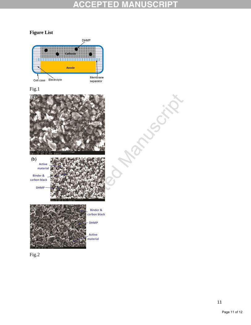
534,000. Fig. 1 depicts the cell structure. Nearly 10 g of the components were thoroughly mixed
Page 3 of 12

4
in an agate mortar with the NCM-CB-PVDF at mass ratio of 93:3:4, and dissolved in N-methyl-
pyrrolidone (NMP; Product No. 328634, Sigma-Aldrich). The mass ratio of the powder to NMP
was 10:4. Sonicator (Model Q55, Qsonica) was employed to form slurry at the 60% power level
for 30 min. The slurry was distributed by a film applicator (EQ-Se-KTQ-100, MTI) with a
thickness of about 200 µm on a 20 µm thick aluminum (Al) charge collector, and dried in a
vacuum oven at 100 oC for 24 h. The dried slurry was compressed to about 2/3 of its original
thickness through calendaring, by using a hardened tool steel rolling mill. The final density of
the cathode layer was about 3.2 g/cm3. Reference anode was produced by using artificial graphite
(AG; EQ-Lib-CMSG, MTI), CB, and PVDF, with the mass ratio of 93:1:6. The procedure was
similar to that of the cathode, except that the charge collector was a 20 µm thick copper (Cu)
foil. The final thickness of cathode was ~100 µm and the final thickness of anode was ~50 µm.
Similar slurry processing approaches were employed to fabricate DHMP-modified cathodes and
anodes, with Darco-KBG angular carbon black microparticles being added into the powder
mixture. The DHMP grain size was sieved to 45--53 m; its amount was 1 wt.% of the total
electrode mass. Fig. 2 shows typical SEM images of DHMP and DHMP-modified cathode and
anode materials.
Full cells were prepared for impact and nail tests. The cathode and anode were cut into
14.3 mm diameter disks. To match the capacity, the active material mass in an anode was nearly
20 mg, ~50% of that of the cathode. In a 2016 battery coin cell case, by using a stainless steel
spring spacer, a cathode disk was pressed on a trilayer polypropylene-polyethylene (PP/PE/PP)
membrane (Product No. 2320, Celgard), supported by an anode disk. About 30 µL electrolyte
(BASF, 1mol/L LiPF6 in 1:1 EC-EMC) was added, and the cell was sealed by a MTI CR2016
crimping machine at 800 psi (5.516 MPa). All coin cells were rested at room temperature for 24
h, and charged and discharged for a few cycles by a MTI BST8-3 Analyzer to ensure that the full
capacity was reached.
To test the effects of DHMP on cathodes, cathode half-cells were assembled by replacing
the anode layer by a 1.1 mm thick, 15.4 mm diameter lithium disk. The electrochemical
performance of the half-cells was examined by the MTI BST8-3 Analyzer, after they had been
rested for 24 h at room temperature. Typical curves are shown in Fig. 3. The voltage range was
3--4.3 V; the charge-discharge rate was 1 C. Reference half-cells were assembled through a
similar procedure, except that cathodes did not contain DHMP.
Page 4 of 12

5
Reference and DHMP-modified full cells were fully charged to 4.6 V at 0.1 C, and tested
in nail penetration (NP) and impact experiments. In a NP test, a 1.59 mm diameter stainless steel
nail was driven by a table-top vise through a charged battery cell, with a constant speed of ~0.5
mm/s. Impact test was performed by dropping a 7 kg cylindrical steel hammer onto the battery
cell. The drop distance was 15 cm. A 6.35 mm diameter brass bead was placed at the center of
the top surface of the battery cell, so as to create a heterogeneous loading. In both NP and impact
tests, the cell temperature was continuously measured by an Omega TT-K-40-25 type-K gage 40
thermocouple equipped with an Omega OM-EL-USB-TC temperature logger data acquisition
system, with the accuracy of 0.5 oC and the record interval of 1 s. The battery cell was insulated
by a 25 mm thick circular Durometer-90A polyurethane clamp from the top and a 12.5 mm thick
circular Durometer-75D polyurethane plate from the bottom, having 9.5 mm diameter circular
hole in the middle. The thermocouple was fixed by a duct tape at the bottom surface of the cell,
5 mm away from the center. The cell was mounted on the bottom plate by 3 layers of insulating
tapes. After the NP or impact test, the battery cell was opened up and the damaged cathode and
anode layers were examined. The experimental results are shown in Figs. 4--7. The variation of
the temperature profiles of nominally same samples was less than the resolution of the
measurement system, for all the testing cases under investigation.
3. Results and Discussion
The SEM image in Fig. 2 shows the DHMP grains. The maximum grain size is ~50 m,
comparable with yet smaller than the cathode and anode layer thickness. Thus, the DHMP
distribution is somewhat two-dimensional (2D). The overall concentration of DHMP is 1%; the
linear number density is ~10%. They are quite uniformly mixed with NCM and AG particles.
Carbon black and DHMP mainly differ in grain size. To reach a high conductivity among
adjacent active material grains, the CB particle size is much smaller, on the nanometer (nm)
scale. The DHMP grain size is larger, so that when the electrode is impacted, sufficient energy
can be stored and trigger DHMP-matrix debonding [17]. Fig. 2(a) indicates that the grain shape
of DHMP is quite irregular.
When the DHMP content is relatively high, higher than 1.5--2 wt.%, the cycling
performance of the modified cells is quite poor, likely caused by the electrolyte absorption and
Page 5 of 12

6
swelling of the large DHMP. With a relatively low DHMP content below 1 wt%, the addition of
DHMP does not have a significant influence on the cycling performance (Fig. 3), as it should,
since the chemical composition of DHMP is similar with CB. The first-cycle Coulombic
efficiency is around 88% for both DHMP modified cathode half-cell and reference half-cell. In
the first dozen of charge-discharge cycles, the capacities of reference and modified cells decrease
by 2%--5%. For the modified cell, there is a drop in capacity at the 8th cycle, which may be
attributed to the difference in volume changes of NCM and DH microparticles, resulting in a
certain initial configuration changes in the initial a few cycles. Nevertheless, the difference
between the modified and the reference cells is within the tolerance of measurement.
In a full-cell nail test, as the cell is penetrated by the electrically conductive nail, the
membrane separation is broken apart and the cathode and the anode form a short circuit. The
internal shorting causes a large current and a rapid heat generation, so that the local temperature
rises in 10--20 s. In a large pouch cell, the temperature would keep increasing to more than 100
oC, due to the difficulty in heat transfer in the interior of the cell [11]. As the cell temperature is
relatively high, more aggressive exothermal reactions are triggered and the temperature increase
is accelerated; i.e. thermal runaway would take place [18]. Eventually, the highly flammable
electrolyte can be ignited, resulting in a catastrophic system failure. In the current study, because
the surface area to volume ratio of the small coin cell is quite large, heat conduction rate is high.
Therefore, as the temperature increase, T, is 5‒6 oC, heat accumulation is balanced by heat
transfer, and the cell temperature reaches the peak value. With the electrical energy being
continuously consumed, after ~20 s the temperature begins to decrease, forming a long tail
section in the temperature profile. The tail length is 10‒20 min, before T converges to zero. The
average temperature decrease rate is ~0.5 oC/min. Fig. 4 suggests that the nail penetration
responses of the reference cell and the DHMP-modified cell are quite similar. The initial
temperature increase rate, the peak temperature, and the post-peak temperature reduction rate do
not exhibit any statistically significant difference. The DHMP-modified cell has a slightly higher
peak temperature, as addition of DHMP increases the conductivity of electrode. Clearly, because
nail penetration occurs at a slow loading rate, the damage promotion effect of DHMP is
negligible.
Fig. 5 shows typical damaged cathode and anode layers of reference and DHMP-
modified cells after nail penetration. The reference and the modified cathodes are nearly the
Page 6 of 12

7
same, agreeing with the temperature profile measurement results. The modified anode contains
more evident markings of electrochemical reactions, the whitened areas. The whitened area is
covered by lithium hydroxide generated by the reactions between the lithiated carbon and H2O,
after the cell is open and the components are exposed to air. It is possible that the anode can be
more aggressively weakened by DHMP than the cathode, and therefore, when the local
temperature is higher the swelling and softening of PVDF binder as well as the associated
electrolyte motion lead to a larger extent of structural change. However, because the cathode is
the dominant component of heat generation and the anode effects are secondary [11], the
temperature profile is not affected.
In the impact test, the temperature profile of the reference cell is somewhat similar to that
of the NP test (Fig. 6). The cell temperature rapidly increases to the peak value, followed by a
gradual decay, indicating that upon the hammer impact, the highly porous, thin polymer
membrane separator ruptures, so that the cathode and anode are in direct contact and the short
circuit aggressively releases and dissipates the stored electrical energy. Because the conductivity
of the active materials is lower than that of stainless steel nail, compared with the NP test the
heat generation rate is relatively slow. Consequently, the initial temperature increases rate, the
peak temperature, and the duration of high-temperature plateau are lower than those of the NP
test. The tail section of the temperature profile lasts longer, since the total stored electric energy
is not related to the cell testing method.
As DHMP is added in the electrodes, the response of the modified cell in the impact test
is different from that of the reference cell. While the initial temperature rise and the peak
temperature are similar, the temperature reduction rate, , in the tail section is much lowered.
For a reference cell, is ~0.2 oC/min. For a modified cell, is ~0.3
oC/min, nearly 50% higher.
The total heat generation, U, can be calculated as the area under the temperature profile curve,
since the specific heats of cell components do not vary during the impact test. The value of U of
the reference cell is ~40% higher than that of the modified cell. It is clear that DHMP suppresses
heat dissipation, which should be attributed to the widespread damaging of the modified cathode.
As the DHMP rises the local stress level and also because of the large stiffness mismatch
between the DHMP and the NCM matrix, the material morphology is greatly changed when the
electrode is impacted. However, compared with the battery cells modified by relatively smooth
fillers [15], the change in temperature profile is at the same level, implying that the DHMP shape
Page 7 of 12

8
may not be a vital factor That is, the effects of the smooth slurry processing and the higher level
of stress concentration are balanced by each other, for the systems under investigation; factors
other than filler shape may be more important. Such factor includes the mismatch of the stiffness
of the DHMP and the electrode matrix; the porosity, which determines the effective bulk
modulus; and the surface free energy, which dominates the interfacial bonding between the
DHMP and the matrix.
As shown in Fig. 7, the features of reference and modified anodes are similar to that of
the NP test, and they may not be the dominant factors of heat generation. The modified cathode
is weakened by DHMP and upon the impact loading, much more severe damages take place. It
may not directly affect the membrane rupture sites, but would raise the resistivity of the
surrounding electrode, i.e. the return path.
4. Concluding Remark
To summarize, addition of 1 wt% angular carbon black microparticles into the cathode
and the anode of a lithium-ion battery cell does not affect the cycling performance. In a nail
penetration test, the cathode behaviors of the reference cell and the modified cell are similar; the
anode of the modified cell demonstrates signs of more aggressive electrochemical reactions,
which however, does not influence the temperature profile. In an impact test, the anode
performance is similar to that of the nail test; the modified cathode is much weakened and thus,
suppresses the heat generation. The totally generated heat is reduced by ~40% in the modified
cell. For the battery systems under investigation, the shape of the filler grains does not play a
critical role in the internal shorting process. These findings shed light on the optimization of
thermal-runaway mitigation techniques.
Acknowledgement
This research was supported by the Advanced Research Projects Agency-Energy (ARPA-
E) (No. DE-AR0000396).
References
[1] M. Broussely, G. Archdale, J. Power Sources 136 (2004) 386-394.
Page 8 of 12
9
[2] P.A. Nelson, K.G. Bloom, , D.W. I Dees, Modeling the Performance and Cost of Lithium-ion
Batteries for Electric-drive Vehicles (No. ANL-11/32), Argonne National Laboratory,
Argonne, IL, United States, 2011.
[3] M. Lowe, S. Tokuoka, T. Trigg, G. Gereffi, Lithium-ion Batteries for Electric Vehicles: The
US Value Chain, Duke University Center on Globalization, Governance & Competitiveness,
2010.
[4] I. Hadjipaschalis, A. Poullikkas, V. Efthimiou Renew. Sustain. Energy Rev. 13 (2009) 1513-
1522.
[5] S. Wasmus, A. Küver, J. Electroanal. Chem. 461 (1999) 14-31.
[6] P.G. Balakrishnan, R. Ramesh, T.P. Kumar, J. Power Sources 155 (2006) 401-414.
[7] Q. Wang, P. Ping, X. Zhao, G. Chu, J. Sun, C. Chen, J. Power Sources 208 (2012) 210-224.
[8] H. Maleki, G. Deng, A. Anani, J. Howard, J. Eelectrochem. Soc.146 (1999) 3224-3229.
[9] G.H. Kim, A. Pesaran, R. Spotnitz, J. Power Sources 170 (2007) 476-489.
[10] S.S. Zhang, J. Power Sources 164 (2007) 351-364.
[11] J.T. Lundquist, C.B. Lundsager, N.I. Palmer, H.J. Troffkin, U.S. Patent No. 4,731,304,
1988.
[12] X.M. Feng, , X.P. Ai, H.X. Yang, Electrochem. Commun. 6 (2004) 1021-1024.
[13] S.A. Khateeb, M.M. Farid, J.R. Selman, S. Al-Hallaj, J. Power Sources 128 (2004)292-307.
[14] A.V. Le, M. Wang, Y. Shi, D. Noelle, Y. Qiao, W. Lu, J. Appl. Phys. 118 (2015) 085312.
[15] A.V. Le, M. Wang, Y. Shi, D. Noelle, Y. Qiao, J. Phys. D: Appl. Phys. 48 (2015) 385501.
[16] Q. Wang, P. Ping, X. Zhao, G. Chu, J. Sun, C. Chen, J. Power Sources 208 (2012) 210--
224.
[17] A.K. Kaw, Mechanics of Composite Materials, CRC Press, Boca Raton, FL, USA, 2005.
[18] D. Doughty, E.P. Roth, Electrochem. Soc. Interface 21 (2012)37-44.
Page 9 of 12

10
Figure Captions
Fig. 1 Schematic of the coin-cell structure.
Fig. 2 Typical SEM images of (a) DHMP, (b) DHMP-modified cathode, and (c) DHMP-
modified anode.
Fig. 3 Typical cycling performance of reference and DHMP-modified cells.
Fig. 4 Typical temperature profiles in nail penetration tests.
Fig. 5 Photos of cell components after nail penetration tests: (a) cathode and (b) anode layers
from a reference cell; (c) cathode and (d) anode layers from a DHMP-modified cell.
Fig. 6 Typical temperature profiles in impact tests.
Fig. 7 Photos of cell components after impact tests: (a) cathode and (b) anode layers from a
reference cell; (c) cathode and (d) anode layers from a DHMP-modified cell.
Page 10 of 12
11
Figure List
Fig.1
Fig.2
Page 11 of 12

12
Fig.3
Fig.4
Fig.5
Fig.6
Fig.7
Page 12 of 12