Effective Dates Generator Owners - NERC Standards/FAC-003-3.pdfFAC-003-3 — Transmission Vegetation...
34
FAC-003-3 — Transmission Vegetation Management Page 1 of 34 Effective Dates Generator Owners There are two effective dates associated with this standard. The first effective date allows Generator Owners time to develop documented maintenance strategies or procedures or processes or specifications as outlined in Requirement R3. In those jurisdictions where regulatory approval is required, Requirement R3 applied to the Generator Owner becomes effective on the first calendar day of the first calendar quarter one year after the date of the order approving the standard from applicable regulatory authorities where such explicit approval for all requirements is required. In those jurisdictions where no regulatory approval is required, Requirement R3 becomes effective on the first day of the first calendar quarter one year following Board of Trustees’ adoption or as otherwise made effective pursuant to the laws applicable to such ERO governmental authorities. The second effective date allows entities time to comply with Requirements R1, R2, R4, R5, R6, and R7. In those jurisdictions where regulatory approval is required, Requirements R1, R2, R4, R5, R6, and R7 applied to the Generator Owner become effective on the first calendar day of the first calendar quarter two years after the date of the order approving the standard from applicable regulatory authorities where such explicit approval for all requirements is required. In those jurisdictions where no regulatory approval is required, Requirements R1, R2, R4, R5, R6, and R7 become effective on the first day of the first calendar quarter two years following Board of Trustees’ adoption or as otherwise made effective pursuant to the laws applicable to such ERO governmental authorities. Effective dates for individual lines when they undergo specific transition cases: 1. A line operated below 200kV, designated by the Planning Coordinator as an element of an Interconnection Reliability Operating Limit (IROL) or designated by the Western Electricity Coordinating Council (WECC) as an element of a Major WECC Transfer Path, becomes subject to this standard the latter of: 1) 12 months after the date the Planning Coordinator or WECC initially designates the line as being an element of an IROL or an element of a Major WECC Transfer Path, or 2) January 1 of the planning year when the line is forecast to become an element of an IROL or an element of a Major WECC Transfer Path.
Transcript of Effective Dates Generator Owners - NERC Standards/FAC-003-3.pdfFAC-003-3 — Transmission Vegetation...

FAC-003-3 — Transmission Vegetation Management
Page 1 of 34
Effective Dates
Generator Owners
There are two effective dates associated with this standard.
The first effective date allows Generator Owners time to develop documented maintenance strategies or procedures or processes or
specifications as outlined in Requirement R3.
In those jurisdictions where regulatory approval is required, Requirement R3 applied to the Generator Owner becomes
effective on the first calendar day of the first calendar quarter one year after the date of the order approving the standard from
applicable regulatory authorities where such explicit approval for all requirements is required. In those jurisdictions where no
regulatory approval is required, Requirement R3 becomes effective on the first day of the first calendar quarter one year following
Board of Trustees’ adoption or as otherwise made effective pursuant to the laws applicable to such ERO governmental authorities.
The second effective date allows entities time to comply with Requirements R1, R2, R4, R5, R6, and R7.
In those jurisdictions where regulatory approval is required, Requirements R1, R2, R4, R5, R6, and R7 applied to the
Generator Owner become effective on the first calendar day of the first calendar quarter two years after the date of the order
approving the standard from applicable regulatory authorities where such explicit approval for all requirements is required. In
those jurisdictions where no regulatory approval is required, Requirements R1, R2, R4, R5, R6, and R7 become effective on the
first day of the first calendar quarter two years following Board of Trustees’ adoption or as otherwise made effective pursuant to the
laws applicable to such ERO governmental authorities.
Effective dates for individual lines when they undergo specific transition cases:
1. A line operated below 200kV, designated by the Planning Coordinator as an element of an Interconnection Reliability
Operating Limit (IROL) or designated by the Western Electricity Coordinating Council (WECC) as an element of a Major
WECC Transfer Path, becomes subject to this standard the latter of: 1) 12 months after the date the Planning Coordinator or
WECC initially designates the line as being an element of an IROL or an element of a Major WECC Transfer Path, or 2)
January 1 of the planning year when the line is forecast to become an element of an IROL or an element of a Major WECC
Transfer Path.

FAC-003-3 — Transmission Vegetation Management
Page 2 of 34
2. A line operated below 200 kV currently subject to this standard as a designated element of an IROL or a Major WECC
Transfer Path which has a specified date for the removal of such designation will no longer be subject to this standard effective
on that specified date.
3. A line operated at 200 kV or above, currently subject to this standard which is a designated element of an IROL or a Major
WECC Transfer Path and which has a specified date for the removal of such designation will be subject to Requirement R2
and no longer be subject to Requirement R1 effective on that specified date.
4. An existing transmission line operated at 200kV or higher which is newly acquired by an asset owner and which was not
previously subject to this standard becomes subject to this standard 12 months after the acquisition date.
5. An existing transmission line operated below 200kV which is newly acquired by an asset owner and which was not previously
subject to this standard becomes subject to this standard 12 months after the acquisition date of the line if at the time of
acquisition the line is designated by the Planning Coordinator as an element of an IROL or by WECC as an element of a Major
WECC Transfer Path.
Transmission Owners [transferred from FAC-003-2]
This standard becomes effective on the first calendar day of the first calendar quarter one year after the date of the order approving the
standard from applicable regulatory authorities where such explicit approval is required. Where no regulatory approval is required, the
standard becomes effective on the first calendar day of the first calendar quarter one year after Board of Trustees adoption.
Effective dates for individual lines when they undergo specific transition cases:
1. A line operated below 200kV, designated by the Planning Coordinator as an element of an Interconnection Reliability
Operating Limit (IROL) or designated by the Western Electricity Coordinating Council (WECC) as an element of a Major
WECC transfer Path, becomes subject to this standard the latter of: 1) 12 months after the date the Planning Coordinator or
WECC initially designates the line as being an element of an IROL or an element of a Major WECC transfer Path, or 2)
January 1 of the planning year when the line is forecast to become an element of an IROL or an element of a Major WECC
transfer Path.
2. A line operated below 200 kV currently subject to this standard as a designated element of an IROL or a Major WECC
Transfer Path which has a specified date for the removal of such designation will no longer be subject to this standard effective
on that specified date.

FAC-003-3 — Transmission Vegetation Management
Page 3 of 34
3. A line operated at 200 kV or above, currently subject to this standard which is a designated element of an IROL or a Major
WECC Transfer Path and which has a specified date for the removal of such designation will be subject to Requirement R2
and no longer be subject to Requirement R1 effective on that specified date.
4. An existing transmission line operated at 200kV or higher which is newly acquired by an asset owner and which was not
previously subject to this standard, becomes subject to this standard 12 months after the acquisition date.
5. An existing transmission line operated below 200kV which is newly acquired by an asset owner and which was not previously
subject to this standard becomes subject to this standard 12 months after the acquisition date of the line if at the time of
acquisition the line is designated by the Planning Coordinator as an element of an IROL or by WECC as an element of a Major
WECC Transfer Path.

FAC-003-3 — Transmission Vegetation Management
Page 4 of 34
A. Introduction
1. Title: Transmission Vegetation Management
2. Number: FAC-003-3
3. Purpose: To maintain a reliable electric transmission system by using a defense-in-
depth strategy to manage vegetation located on transmission rights of way
(ROW) and minimize encroachments from vegetation located adjacent to
the ROW, thus preventing the risk of those vegetation-related outages that
could lead to Cascading.
4. Applicability
4.1. Functional Entities:
4.1.1. Applicable Transmission Owners
4.1.1.1 Transmission Owners that own Transmission Facilities defined in 4.2.
4.1.2 Applicable Generator Owners
4.1.2.1 Generator Owners that own generation Facilities defined in 4.3
4.2. Transmission Facilities: Defined below (referred to as “applicable lines”),
including but not limited to those that cross lands owned by federal1, state,
provincial, public, private, or tribal entities:
4.2. 1 Each overhead transmission line operated at 200kV or higher.
4.2.2 Each overhead transmission line operated below 200kV identified as an element
of an IROL under NERC Standard FAC-014 by the Planning Coordinator.
4.2.3 Each overhead transmission line operated below 200 kV identified as an
element of a Major WECC Transfer Path in the Bulk Electric System by WECC.
4.2.4 Each overhead transmission line identified above (4.2.1 through 4.2.3) located
outside the fenced area of the switchyard, station or substation and any portion of the
span of the transmission line that is crossing the substation fence.
4.3. Generation Facilities: Defined below (referred to as “applicable lines”),
including but not limited to those that cross lands owned by federal2, state,
provincial, public, private, or tribal entities:
4.3.1 Overhead transmission lines that (1) extend greater than one mile or 1.609
kilometers beyond the fenced area of the generating station switchyard to the point of
interconnection with a Transmission Owner’s Facility or (2) do not have a clear line
1 EPAct 2005 section 1211c: “Access approvals by Federal agencies.” 2 Id.

FAC-003-3 — Transmission Vegetation Management
Page 5 of 34
of sight3 from the generating station switchyard fence to the point of interconnection
with a Transmission Owner’s Facility and are:
4.3.1.1 Operated at 200kV or higher; or
4.3.1.2 Operated below 200kV identified as an element of an IROL under NERC
Standard FAC-014 by the Planning Coordinator; or
4.3.1.3 Operated below 200 kV identified as an element of a Major WECC Transfer
Path in the Bulk Electric System by WECC.
Enforcement:
The Requirements within a Reliability Standard govern and will be enforced. The Requirements
within a Reliability Standard define what an entity must do to be compliant and binds an entity to
certain obligations of performance under Section 215 of the Federal Power Act. Compliance
will in all cases be measured by determining whether a party met or failed to meet the Reliability
Standard Requirement given the specific facts and circumstances of its use, ownership or
operation of the bulk power system.
Measures provide guidance on assessing non-compliance with the Requirements. Measures are
the evidence that could be presented to demonstrate compliance with a Reliability Standard
Requirement and are not intended to contain the quantitative metrics for determining satisfactory
performance nor to limit how an entity may demonstrate compliance if valid alternatives to
demonstrating compliance are available in a specific case. A Reliability Standard may be
enforced in the absence of specified Measures.
Entities must comply with the “Compliance” section in its entirety, including the Administrative
Procedure that sets forth, among other things, reporting requirements.
The “Guideline and Technical Basis” section, the Background section and text boxes with
“Examples” and “Rationale” are provided for informational purposes. They are designed to
convey guidance from NERC’s various activities. The “Guideline and Technical Basis” section
and text boxes with “Examples” and “Rationale” are not intended to establish new Requirements
under NERC’s Reliability Standards or to modify the Requirements in any existing NERC
Reliability Standard. Implementation of the “Guideline and Technical Basis” section, the
Background section and text boxes with “Examples” and “Rationale” is not a substitute for
compliance with Requirements in NERC’s Reliability Standards.”
5. Background:
This standard uses three types of requirements to provide layers of protection to
prevent vegetation related outages that could lead to Cascading:
3 “Clear line of sight” means the distance that can be seen by the average person without special instrumentation
(e.g., binoculars, telescope, spyglasses, etc.) on a clear day.

FAC-003-3 — Transmission Vegetation Management
Page 6 of 34
a) Performance-based defines a particular reliability objective or outcome to be
achieved. In its simplest form, a results-based requirement has four components:
who, under what conditions (if any), shall perform what action, to achieve what
particular bulk power system performance result or outcome?
b) Risk-based preventive requirements to reduce the risks of failure to acceptable
tolerance levels. A risk-based reliability requirement should be framed as: who,
under what conditions (if any), shall perform what action, to achieve what particular
result or outcome that reduces a stated risk to the reliability of the bulk power
system?
c) Competency-based defines a minimum set of capabilities an entity needs to
have to demonstrate it is able to perform its designated reliability functions. A
competency-based reliability requirement should be framed as: who, under what
conditions (if any), shall have what capability, to achieve what particular result or
outcome to perform an action to achieve a result or outcome or to reduce a risk to the
reliability of the bulk power system?
The defense-in-depth strategy for reliability standards development recognizes that
each requirement in a NERC reliability standard has a role in preventing system
failures, and that these roles are complementary and reinforcing. Reliability
standards should not be viewed as a body of unrelated requirements, but rather should
be viewed as part of a portfolio of requirements designed to achieve an overall
defense-in-depth strategy and comport with the quality objectives of a reliability
standard.
This standard uses a defense-in-depth approach to improve the reliability of the electric
Transmission system by:
• Requiring that vegetation be managed to prevent vegetation encroachment inside
the flash-over clearance (R1 and R2);
• Requiring documentation of the maintenance strategies, procedures, processes and
specifications used to manage vegetation to prevent potential flash-over
conditions including consideration of 1) conductor dynamics and 2) the
interrelationships between vegetation growth rates, control methods and the
inspection frequency (R3);
• Requiring timely notification to the appropriate control center of vegetation
conditions that could cause a flash-over at any moment (R4);
• Requiring corrective actions to ensure that flash-over distances will not be
violated due to work constrains such as legal injunctions (R5);
• Requiring inspections of vegetation conditions to be performed annually (R6);
and
• Requiring that the annual work needed to prevent flash-over is completed (R7).
For this standard, the requirements have been developed as follows:
Performance-based: Requirements 1 and 2
Competency-based: Requirement 3

FAC-003-3 — Transmission Vegetation Management
Page 7 of 34
Risk-based: Requirements 4, 5, 6 and 7
R3 serves as the first line of defense by ensuring that entities understand the problem
they are trying to manage and have fully developed strategies and plans to manage the
problem. R1, R2, and R7 serve as the second line of defense by requiring that entities
carry out their plans and manage vegetation. R6, which requires inspections, may be
either a part of the first line of defense (as input into the strategies and plans) or as a
third line of defense (as a check of the first and second lines of defense). R4 serves as
the final line of defense, as it addresses cases in which all the other lines of defense
have failed.
Major outages and operational problems have resulted from interference between
overgrown vegetation and transmission lines located on many types of lands and
ownership situations. Adherence to the standard requirements for applicable lines on
any kind of land or easement, whether they are Federal Lands, state or provincial
lands, public or private lands, franchises, easements or lands owned in fee, will
reduce and manage this risk. For the purpose of the standard the term “public lands”
includes municipal lands, village lands, city lands, and a host of other governmental
entities.
This standard addresses vegetation management along applicable overhead lines and
does not apply to underground lines, submarine lines or to line sections inside an
electric station boundary.
This standard focuses on transmission lines to prevent those vegetation related
outages that could lead to Cascading. It is not intended to prevent customer outages
due to tree contact with lower voltage distribution system lines. For example,
localized customer service might be disrupted if vegetation were to make contact with
a 69kV transmission line supplying power to a 12kV distribution station. However,
this standard is not written to address such isolated situations which have little impact
on the overall electric transmission system.
Since vegetation growth is constant and always present, unmanaged vegetation poses
an increased outage risk, especially when numerous transmission lines are operating
at or near their Rating. This can present a significant risk of consecutive line failures
when lines are experiencing large sags thereby leading to Cascading. Once the first
line fails the shift of the current to the other lines and/or the increasing system loads
will lead to the second and subsequent line failures as contact to the vegetation under
those lines occurs. Conversely, most other outage causes (such as trees falling into
lines, lightning, animals, motor vehicles, etc.) are not an interrelated function of the
shift of currents or the increasing system loading. These events are not any more
likely to occur during heavy system loads than any other time. There is no cause-
effect relationship which creates the probability of simultaneous occurrence of other
such events. Therefore these types of events are highly unlikely to cause large-scale
grid failures. Thus, this standard places the highest priority on the management of
vegetation to prevent vegetation grow-ins.
FAC-003-3 — Transmission Vegetation Management
Page 8 of 34
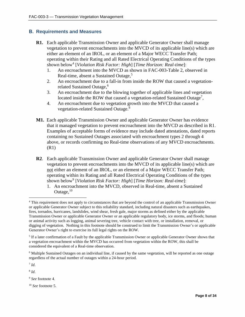
B. Requirements and Measures
R1. Each applicable Transmission Owner and applicable Generator Owner shall manage
vegetation to prevent encroachments into the MVCD of its applicable line(s) which are
either an element of an IROL, or an element of a Major WECC Transfer Path;
operating within their Rating and all Rated Electrical Operating Conditions of the types
shown below4 [Violation Risk Factor: High] [Time Horizon: Real-time]:
1. An encroachment into the MVCD as shown in FAC-003-Table 2, observed in
Real-time, absent a Sustained Outage,5
2. An encroachment due to a fall-in from inside the ROW that caused a vegetation-
related Sustained Outage,6
3. An encroachment due to the blowing together of applicable lines and vegetation
located inside the ROW that caused a vegetation-related Sustained Outage7,
4. An encroachment due to vegetation growth into the MVCD that caused a
vegetation-related Sustained Outage.8
M1. Each applicable Transmission Owner and applicable Generator Owner has evidence
that it managed vegetation to prevent encroachment into the MVCD as described in R1.
Examples of acceptable forms of evidence may include dated attestations, dated reports
containing no Sustained Outages associated with encroachment types 2 through 4
above, or records confirming no Real-time observations of any MVCD encroachments.
(R1)
R2. Each applicable Transmission Owner and applicable Generator Owner shall manage
vegetation to prevent encroachments into the MVCD of its applicable line(s) which are
not either an element of an IROL, or an element of a Major WECC Transfer Path;
operating within its Rating and all Rated Electrical Operating Conditions of the types
shown below9 [Violation Risk Factor: High] [Time Horizon: Real-time]:
1. An encroachment into the MVCD, observed in Real-time, absent a Sustained
Outage,10
4 This requirement does not apply to circumstances that are beyond the control of an applicable Transmission Owner
or applicable Generator Owner subject to this reliability standard, including natural disasters such as earthquakes,
fires, tornados, hurricanes, landslides, wind shear, fresh gale, major storms as defined either by the applicable
Transmission Owner or applicable Generator Owner or an applicable regulatory body, ice storms, and floods; human
or animal activity such as logging, animal severing tree, vehicle contact with tree, or installation, removal, or
digging of vegetation. Nothing in this footnote should be construed to limit the Transmission Owner’s or applicable
Generator Owner’s right to exercise its full legal rights on the ROW.
5 If a later confirmation of a Fault by the applicable Transmission Owner or applicable Generator Owner shows that
a vegetation encroachment within the MVCD has occurred from vegetation within the ROW, this shall be
considered the equivalent of a Real-time observation.
6 Multiple Sustained Outages on an individual line, if caused by the same vegetation, will be reported as one outage
regardless of the actual number of outages within a 24-hour period.
7 Id.
8 Id.
9 See footnote 4.
10 See footnote 5.
FAC-003-3 — Transmission Vegetation Management
Page 9 of 34
2. An encroachment due to a fall-in from inside the ROW that caused a vegetation-
related Sustained Outage,11
3. An encroachment due to blowing together of applicable lines and vegetation located
inside the ROW that caused a vegetation-related Sustained Outage,12
4. An encroachment due to vegetation growth into the line MVCD that caused a
vegetation-related Sustained Outage13
M2. Each applicable Transmission Owner and applicable Generator Owner has evidence
that it managed vegetation to prevent encroachment into the MVCD as described in R2.
Examples of acceptable forms of evidence may include dated attestations, dated reports
containing no Sustained Outages associated with encroachment types 2 through 4
above, or records confirming no Real-time observations of any MVCD encroachments.
(R2)
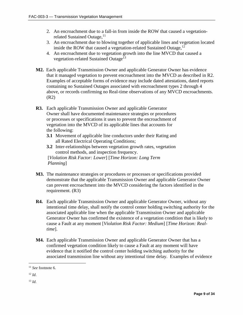
R3. Each applicable Transmission Owner and applicable Generator
Owner shall have documented maintenance strategies or procedures
or processes or specifications it uses to prevent the encroachment of
vegetation into the MVCD of its applicable lines that accounts for
the following:
3.1 Movement of applicable line conductors under their Rating and
all Rated Electrical Operating Conditions;
3.2 Inter-relationships between vegetation growth rates, vegetation
control methods, and inspection frequency.
[Violation Risk Factor: Lower] [Time Horizon: Long Term
Planning]
M3. The maintenance strategies or procedures or processes or specifications provided
demonstrate that the applicable Transmission Owner and applicable Generator Owner
can prevent encroachment into the MVCD considering the factors identified in the
requirement. (R3)
R4. Each applicable Transmission Owner and applicable Generator Owner, without any
intentional time delay, shall notify the control center holding switching authority for the
associated applicable line when the applicable Transmission Owner and applicable
Generator Owner has confirmed the existence of a vegetation condition that is likely to
cause a Fault at any moment [Violation Risk Factor: Medium] [Time Horizon: Real-
time].
M4. Each applicable Transmission Owner and applicable Generator Owner that has a
confirmed vegetation condition likely to cause a Fault at any moment will have
evidence that it notified the control center holding switching authority for the
associated transmission line without any intentional time delay. Examples of evidence
11 See footnote 6.
12 Id.
13 Id.

FAC-003-3 — Transmission Vegetation Management
Page 10 of 34
may include control center logs, voice recordings, switching orders, clearance orders
and subsequent work orders. (R4)
R5. When a applicable Transmission Owner and applicable Generator Owner is constrained
from performing vegetation work on an applicable line operating within its Rating and
all Rated Electrical Operating Conditions, and the constraint may lead to a vegetation
encroachment into the MVCD prior to the implementation of the next annual work
plan, then the applicable Transmission Owner or applicable Generator Owner shall take
corrective action to ensure continued vegetation management to prevent encroachments
[Violation Risk Factor: Medium] [Time Horizon: Operations Planning].
M5. Each applicable Transmission Owner and applicable Generator Owner has evidence of
the corrective action taken for each constraint where an applicable transmission line
was put at potential risk. Examples of acceptable forms of evidence may include
initially-planned work orders, documentation of constraints from landowners, court
orders, inspection records of increased monitoring, documentation of the de-rating of
lines, revised work orders, invoices, or evidence that the line was de-energized. (R5)
R6. Each applicable Transmission Owner and applicable Generator Owner shall perform a
Vegetation Inspection of 100% of its applicable transmission lines (measured in units
of choice - circuit, pole line, line miles or kilometers, etc.) at least once per calendar
year and with no more than 18 calendar months between inspections on the same
ROW14 [Violation Risk Factor: Medium] [Time Horizon: Operations Planning].
M6. Each applicable Transmission Owner and applicable Generator Owner has evidence
that it conducted Vegetation Inspections of the transmission line ROW for all
applicable lines at least once per calendar year but with no more than 18 calendar
months between inspections on the same ROW. Examples of acceptable forms of
evidence may include completed and dated work orders, dated invoices, or dated
inspection records. (R6)
R7. Each applicable Transmission Owner and applicable Generator Owner shall complete
100% of its annual vegetation work plan of applicable lines to ensure no vegetation
encroachments occur within the MVCD. Modifications to the work plan in response to
changing conditions or to findings from vegetation inspections may be made (provided
they do not allow encroachment of vegetation into the MVCD) and must be
documented. The percent completed calculation is based on the number of units
actually completed divided by the number of units in the final amended plan (measured
in units of choice - circuit, pole line, line miles or kilometers, etc.) Examples of reasons
for modification to annual plan may include [Violation Risk Factor: Medium] [Time
Horizon: Operations Planning]:
14 When the applicable Transmission Owner or applicable Generator Owner is prevented from performing a
Vegetation Inspection within the timeframe in R6 due to a natural disaster, the TO or GO is granted a time extension
that is equivalent to the duration of the time the TO or GO was prevented from performing the Vegetation
Inspection.

FAC-003-3 — Transmission Vegetation Management
Page 11 of 34
Change in expected growth rate/ environmental factors
Circumstances that are beyond the control of an applicable Transmission Owner or
applicable Generator Owner15
Rescheduling work between growing seasons
Crew or contractor availability/ Mutual assistance agreements
Identified unanticipated high priority work
Weather conditions/Accessibility
Permitting delays
Land ownership changes/Change in land use by the landowner
Emerging technologies
M7. Each applicable Transmission Owner and applicable Generator Owner has evidence
that it completed its annual vegetation work plan for its applicable lines. Examples of
acceptable forms of evidence may include a copy of the completed annual work plan
(as finally modified), dated work orders, dated invoices, or dated inspection records.
(R7)
C. Compliance
1. Compliance Monitoring Process
1.1 Compliance Enforcement Authority
The Regional Entity shall serve as the Compliance Enforcement Authority unless the
applicable entity is owned, operated, or controlled by the Regional Entity. In such
cases the ERO or a Regional entity approved by FERC or other applicable
governmental authority shall serve as the CEA.
For NERC, a third-party monitor without vested interest in the outcome for
NERC shall serve as the Compliance Enforcement Authority.
1.2 Evidence Retention
The following evidence retention periods identify the period of time an entity is
required to retain specific evidence to demonstrate compliance. For instances
where the evidence retention period specified below is shorter than the time since
the last audit, the Compliance Enforcement Authority may ask an entity to
provide other evidence to show that it was compliant for the full time period since
the last audit.
The applicable Transmission Owner and applicable Generator Owner retains data
or evidence to show compliance with Requirements R1, R2, R3, R5, R6 and R7,
Measures M1, M2, M3, M5, M6 and M7 for three calendar years unless directed
by its Compliance Enforcement Authority to retain specific evidence for a longer
period of time as part of an investigation.
15 Circumstances that are beyond the control of an applicable Transmission Owner or applicable Generator Owner
include but are not limited to natural disasters such as earthquakes, fires, tornados, hurricanes, landslides, ice storms,
floods, or major storms as defined either by the TO or GO or an applicable regulatory body.

FAC-003-3 — Transmission Vegetation Management
Page 12 of 34
The applicable Transmission Owner and applicable Generator Owner retains data
or evidence to show compliance with Requirement R4, Measure M4 for most
recent 12 months of operator logs or most recent 3 months of voice recordings or
transcripts of voice recordings, unless directed by its Compliance Enforcement
Authority to retain specific evidence for a longer period of time as part of an
investigation.
If a applicable Transmission Owner or applicable Generator Owner is found non-
compliant, it shall keep information related to the non-compliance until found
compliant or for the time period specified above, whichever is longer.
The Compliance Enforcement Authority shall keep the last audit records and all
requested and submitted subsequent audit records.
1.3 Compliance Monitoring and Enforcement Processes:
Compliance Audit
Self-Certification
Spot Checking
Compliance Violation Investigation
Self-Reporting
Complaint
Periodic Data Submittal
1.4 Additional Compliance Information
Periodic Data Submittal: The applicable Transmission Owner and applicable
Generator Owner will submit a quarterly report to its Regional Entity, or the
Regional Entity’s designee, identifying all Sustained Outages of applicable lines
operated within their Rating and all Rated Electrical Operating Conditions as
determined by the applicable Transmission Owner or applicable Generator Owner
to have been caused by vegetation, except as excluded in footnote 2, and
including as a minimum the following:
o The name of the circuit(s), the date, time and duration of the outage;
the voltage of the circuit; a description of the cause of the outage; the
category associated with the Sustained Outage; other pertinent
comments; and any countermeasures taken by the applicable
Transmission Owner or applicable Generator Owner.
A Sustained Outage is to be categorized as one of the following:
o Category 1A — Grow-ins: Sustained Outages caused by vegetation
growing into applicable lines, that are identified as an element of an

FAC-003-3 — Transmission Vegetation Management
Page 13 of 34
IROL or Major WECC Transfer Path, by vegetation inside and/or
outside of the ROW;
o Category 1B — Grow-ins: Sustained Outages caused by vegetation
growing into applicable lines, but are not identified as an element of an
IROL or Major WECC Transfer Path, by vegetation inside and/or
outside of the ROW;
o Category 2A — Fall-ins: Sustained Outages caused by vegetation
falling into applicable lines that are identified as an element of an
IROL or Major WECC Transfer Path, from within the ROW;
o Category 2B — Fall-ins: Sustained Outages caused by vegetation
falling into applicable lines, but are not identified as an element of an
IROL or Major WECC Transfer Path, from within the ROW;
o Category 3 — Fall-ins: Sustained Outages caused by vegetation falling
into applicable lines from outside the ROW;
o Category 4A — Blowing together: Sustained Outages caused by
vegetation and applicable lines that are identified as an element of an
IROL or Major WECC Transfer Path, blowing together from within
the ROW.
o Category 4B — Blowing together: Sustained Outages caused by
vegetation and applicable lines, but are not identified as an element of
an IROL or Major WECC Transfer Path, blowing together from within
the ROW.
The Regional Entity will report the outage information provided by applicable
Transmission Owners and applicable Generator Owners, as per the above,
quarterly to NERC, as well as any actions taken by the Regional Entity as a result
of any of the reported Sustained Outages.
FAC-003-3 — Transmission Vegetation Management
Page 14 of 34
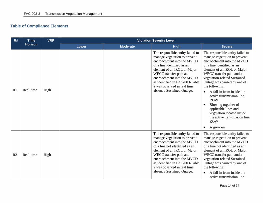
Table of Compliance Elements
R# Time Horizon
VRF Violation Severity Level
Lower Moderate High Severe
R1 Real-time High
The responsible entity failed to
manage vegetation to prevent
encroachment into the MVCD
of a line identified as an
element of an IROL or Major
WECC transfer path and
encroachment into the MVCD
as identified in FAC-003-Table
2 was observed in real time
absent a Sustained Outage.
The responsible entity failed to
manage vegetation to prevent
encroachment into the MVCD
of a line identified as an
element of an IROL or Major
WECC transfer path and a
vegetation-related Sustained
Outage was caused by one of
the following:
A fall-in from inside the
active transmission line
ROW
Blowing together of
applicable lines and
vegetation located inside
the active transmission line
ROW
A grow-in
R2 Real-time High
The responsible entity failed to
manage vegetation to prevent
encroachment into the MVCD
of a line not identified as an
element of an IROL or Major
WECC transfer path and
encroachment into the MVCD
as identified in FAC-003-Table
2 was observed in real time
absent a Sustained Outage.
The responsible entity failed to
manage vegetation to prevent
encroachment into the MVCD
of a line not identified as an
element of an IROL or Major
WECC transfer path and a
vegetation-related Sustained
Outage was caused by one of
the following:
A fall-in from inside the
active transmission line

FAC-003-3 — Transmission Vegetation Management
Page 15 of 34
ROW
Blowing together of
applicable lines and
vegetation located inside
the active transmission line
ROW
A grow-in
R3 Long-Term
Planning Lower
The responsible entity has
maintenance strategies or
documented procedures or
processes or specifications but
has not accounted for the
inter-relationships between
vegetation growth rates,
vegetation control methods,
and inspection frequency, for
the responsible entity’s
applicable lines. (Requirement
R3, Part 3.2)
The responsible entity has
maintenance strategies or
documented procedures or
processes or specifications but
has not accounted for the
movement of transmission line
conductors under their Rating
and all Rated Electrical
Operating Conditions, for the
responsible entity’s applicable
lines. Requirement R3, Part
3.1)
The responsible entity does not
have any maintenance
strategies or documented
procedures or processes or
specifications used to prevent
the encroachment of vegetation
into the MVCD, for the
responsible entity’s applicable
lines.
R4 Real-time Medium
The responsible entity
experienced a confirmed
vegetation threat and notified
the control center holding
switching authority for that
applicable line, but there was
intentional delay in that
notification.
The responsible entity
experienced a confirmed
vegetation threat and did not
notify the control center
holding switching authority for
that applicable line.
R5 Operations
Planning Medium
The responsible entity did not
take corrective action when it
was constrained from
performing planned vegetation
work where an applicable line
was put at potential risk.
R6 Operations Medium The responsible entity The responsible entity failed The responsible entity failed to The responsible entity failed to

FAC-003-3 — Transmission Vegetation Management
Page 16 of 34
Planning failed to inspect 5% or less
of its applicable lines
(measured in units of
choice - circuit, pole line,
line miles or kilometers,
etc.)
to inspect more than 5% up to
and including 10% of its
applicable lines (measured in
units of choice - circuit, pole
line, line miles or kilometers,
etc.).
inspect more than 10% up to
and including 15% of its
applicable lines (measured in
units of choice - circuit, pole
line, line miles or kilometers,
etc.).
inspect more than 15% of its
applicable lines (measured in
units of choice - circuit, pole
line, line miles or kilometers,
etc.).
R7 Operations
Planning Medium
The responsible entity
failed to complete 5% or
less of its annual
vegetation work plan for
its applicable lines (as
finally modified).
The responsible entity failed
to complete more than 5% and
up to and including 10% of its
annual vegetation work plan
for its applicable lines (as
finally modified).
The responsible entity failed to
complete more than 10% and
up to and including 15% of its
annual vegetation work plan
for its applicable lines (as
finally modified).
The responsible entity failed to
complete more than 15% of its
annual vegetation work plan for
its applicable lines (as finally
modified).
D. Regional Differences None.
E. Interpretations None.
F. Associated Documents Guideline and Technical Basis (attached).

FAC-003-3 — Transmission Vegetation Management
Page 17 of 34
GGuuiiddeelliinnee aanndd TTeecchhnniiccaall BBaassiiss
Effective dates:
The first two sentences of the Effective Dates section is standard language used in most NERC
standards to cover the general effective date and is sufficient to cover the vast majority of
situations. Five special cases are needed to cover effective dates for individual lines which
undergo transitions after the general effective date. These special cases cover the effective dates
for those lines which are initially becoming subject to the standard, those lines which are
changing their applicability within the standard, and those lines which are changing in a manner
that removes their applicability to the standard.
Case 1 is needed because the Planning Coordinators may designate lines below 200 kV to
become elements of an IROL or Major WECC Transfer Path in a future Planning Year (PY).
For example, studies by the Planning Coordinator in 2011 may identify a line to have that
designation beginning in PY 2021, ten years after the planning study is performed. It is not
intended for the Standard to be immediately applicable to, or in effect for, that line until that
future PY begins. The effective date provision for such lines ensures that the line will become
subject to the standard on January 1 of the PY specified with an allowance of at least 12 months
for the applicable Transmission Owner or applicable Generator Owner to make the necessary
preparations to achieve compliance on that line. The table below has some explanatory
examples of the application.
Date that Planning
Study is
completed
PY the line
will become
an IROL
element Date 1 Date 2
Effective Date
The latter of Date 1
or Date 2
05/15/2011 2012 05/15/2012 01/01/2012 05/15/2012
05/15/2011 2013 05/15/2012 01/01/2013 01/01/2013
05/15/2011 2014 05/15/2012 01/01/2014 01/01/2014
05/15/2011 2021 05/15/2012 01/01/2021 01/01/2021
Case 2 is needed because a line operating below 200kV designated as an element of an IROL or
Major WECC Transfer Path may be removed from that designation due to system improvements,
changes in generation, changes in loads or changes in studies and analysis of the network.
Case 3 is needed because a line operating at 200 kV or above that once was designated as an
element of an IROL or Major WECC Transfer Path may be removed from that designation due
to system improvements, changes in generation, changes in loads or changes in studies and
analysis of the network. Such changes result in the need to apply R1 to that line until that date is
reached and then to apply R2 to that line thereafter.
Case 4 is needed because an existing line that is to be operated at 200 kV or above can be
acquired by an applicable Transmission Owner or applicable Generator Owner from a third party

FAC-003-3 — Transmission Vegetation Management
Page 18 of 34
such as a Distribution Provider or other end-user who was using the line solely for local
distribution purposes, but the applicable Transmission Owner or applicable Generator Owner,
upon acquisition, is incorporating the line into the interconnected electrical energy transmission
network which will thereafter make the line subject to the standard.
Case 5 is needed because an existing line that is operated below 200 kV can be acquired by an
applicable Transmission Owner or applicable Generator Owner from a third party such as a
Distribution Provider or other end-user who was using the line solely for local distribution
purposes, but the applicable Transmission Owner or applicable Generator Owner, upon
acquisition, is incorporating the line into the interconnected electrical energy transmission
network. In this special case the line upon acquisition was designated as an element of an
Interconnection Reliability Operating Limit (IROL) or an element of a Major WECC Transfer
Path.
Defined Terms:
Explanation for revising the definition of ROW:
The current NERC glossary definition of Right of Way has been modified to include Generator
Owners and to address the matter set forth in Paragraph 734 of FERC Order 693. The Order
pointed out that Transmission Owners may in some cases own more property or rights than are
needed to reliably operate transmission lines. This modified definition represents a slight but
significant departure from the strict legal definition of “right of way” in that this definition is based
on engineering and construction considerations that establish the width of a corridor from a
technical basis. The pre-2007 maintenance records are included in the revised definition to allow
the use of such vegetation widths if there were no engineering or construction standards that
referenced the width of right of way to be maintained for vegetation on a particular line but the
evidence exists in maintenance records for a width that was in fact maintained prior to this
standard becoming mandatory. Such widths may be the only information available for lines that
had limited or no vegetation easement rights and were typically maintained primarily to ensure
public safety. This standard does not require additional easement rights to be purchased to satisfy a
minimum right of way width that did not exist prior to this standard becoming mandatory.
The Project 2010-07 team further modified that proposed definition to include applicable
Generator Owners.
Explanation for revising the definition of Vegetation Inspections:
The current glossary definition of this NERC term is being modified to include Generator Owners
and to allow both maintenance inspections and vegetation inspections to be performed
concurrently. This allows potential efficiencies, especially for those lines with minimal vegetation
and/or slow vegetation growth rates.
The Project 2010-07 team further modified that proposed definition to include applicable
Generator Owners.

FAC-003-3 — Transmission Vegetation Management
Page 19 of 34
Explanation of the definition of the MVCD:
The MVCD is a calculated minimum distance that is derived from the Gallet Equations. This is a
method of calculating a flash over distance that has been used in the design of high voltage
transmission lines. Keeping vegetation away from high voltage conductors by this distance will
prevent voltage flash-over to the vegetation. See the explanatory text below for Requirement R3
and associated Figure 1. Table 2 below provides MVCD values for various voltages and altitudes.
Details of the equations and an example calculation are provided in Appendix 1 of the Technical
Reference Document.
Requirements R1 and R2:
R1 and R2 are performance-based requirements. The reliability objective or outcome to be
achieved is the management of vegetation such that there are no vegetation encroachments within
a minimum distance of transmission lines. Content-wise, R1 and R2 are the same requirements;
however, they apply to different Facilities. Both R1 and R2 require each applicable Transmission
Owner or applicable Generator Owner to manage vegetation to prevent encroachment within the
MVCD of transmission lines. R1 is applicable to lines that are identified as an element of an IROL
or Major WECC Transfer Path. R2 is applicable to all other lines that are not elements of IROLs,
and not elements of Major WECC Transfer Paths.
The separation of applicability (between R1 and R2) recognizes that inadequate vegetation
management for an applicable line that is an element of an IROL or a Major WECC Transfer
Path is a greater risk to the interconnected electric transmission system than applicable lines that
are not elements of IROLs or Major WECC Transfer Paths. Applicable lines that are not
elements of IROLs or Major WECC Transfer Paths do require effective vegetation management,
but these lines are comparatively less operationally significant. As a reflection of this difference
in risk impact, the Violation Risk Factors (VRFs) are assigned as High for R1 and High for R2.
Requirements R1 and R2 state that if inadequate vegetation management allows vegetation to
encroach within the MVCD distance as shown in Table 2, it is a violation of the standard. Table
2 distances are the minimum clearances that will prevent spark-over based on the Gallet
equations as described more fully in the Technical Reference document.
These requirements assume that transmission lines and their conductors are operating within
their Rating. If a line conductor is intentionally or inadvertently operated beyond its Rating and
Rated Electrical Operating Condition (potentially in violation of other standards), the occurrence
of a clearance encroachment may occur solely due to that condition. For example, emergency
actions taken by an applicable Transmission Owner or applicable Generator Owner or Reliability
Coordinator to protect an Interconnection may cause excessive sagging and an outage. Another
example would be ice loading beyond the line’s Rating and Rated Electrical Operating
Condition. Such vegetation-related encroachments and outages are not violations of this
standard.
Evidence of failures to adequately manage vegetation include real-time observation of a
vegetation encroachment into the MVCD (absent a Sustained Outage), or a vegetation-related
encroachment resulting in a Sustained Outage due to a fall-in from inside the ROW, or a
vegetation-related encroachment resulting in a Sustained Outage due to the blowing together of

FAC-003-3 — Transmission Vegetation Management
Page 20 of 34
the lines and vegetation located inside the ROW, or a vegetation-related encroachment resulting
in a Sustained Outage due to a grow-in. Faults which do not cause a Sustained outage and which
are confirmed to have been caused by vegetation encroachment within the MVCD are considered
the equivalent of a Real-time observation for violation severity levels.
With this approach, the VSLs for R1 and R2 are structured such that they directly correlate to the
severity of a failure of an applicable Transmission Owner or applicable Generator Owner to
manage vegetation and to the corresponding performance level of the Transmission Owner’s
vegetation program’s ability to meet the objective of “preventing the risk of those vegetation
related outages that could lead to Cascading.” Thus violation severity increases with an
applicable Transmission Owner’s or applicable Generator Owner’s inability to meet this goal and
its potential of leading to a Cascading event. The additional benefits of such a combination are
that it simplifies the standard and clearly defines performance for compliance. A performance-
based requirement of this nature will promote high quality, cost effective vegetation management
programs that will deliver the overall end result of improved reliability to the system.
Multiple Sustained Outages on an individual line can be caused by the same vegetation. For
example initial investigations and corrective actions may not identify and remove the actual
outage cause then another outage occurs after the line is re-energized and previous high
conductor temperatures return. Such events are considered to be a single vegetation-related
Sustained Outage under the standard where the Sustained Outages occur within a 24 hour period.
The MVCD is a calculated minimum distance stated in feet (or meters) to prevent spark-over, for
various altitudes and operating voltages that is used in the design of Transmission Facilities.
Keeping vegetation from entering this space will prevent transmission outages.
If the applicable Transmission Owner or applicable Generator Owner has applicable lines
operated at nominal voltage levels not listed in Table 2, then the applicable TO or applicable GO
should use the next largest clearance distance based on the next highest nominal voltage in the
table to determine an acceptable distance.
Requirement R3: R3 is a competency based requirement concerned with the maintenance strategies, procedures,
processes, or specifications, an applicable Transmission Owner or applicable Generator Owner
uses for vegetation management.
An adequate transmission vegetation management program formally establishes the approach the
applicable Transmission Owner or applicable Generator Owner uses to plan and perform
vegetation work to prevent transmission Sustained Outages and minimize risk to the transmission
system. The approach provides the basis for evaluating the intent, allocation of appropriate
resources, and the competency of the applicable Transmission Owner or applicable Generator
Owner in managing vegetation. There are many acceptable approaches to manage vegetation
and avoid Sustained Outages. However, the applicable Transmission Owner or applicable
Generator Owner must be able to show the documentation of its approach and how it conducts
work to maintain clearances.
An example of one approach commonly used by industry is ANSI Standard A300, part 7.
However, regardless of the approach a utility uses to manage vegetation, any approach an

FAC-003-3 — Transmission Vegetation Management
Page 21 of 34
applicable Transmission Owner or applicable Generator Owner chooses to use will generally
contain the following elements:
1. the maintenance strategy used (such as minimum vegetation-to-conductor distance or
maximum vegetation height) to ensure that MVCD clearances are never violated.
2. the work methods that the applicable Transmission Owner or applicable Generator
Owner uses to control vegetation
3. a stated Vegetation Inspection frequency
4. an annual work plan
The conductor’s position in space at any point in time is continuously changing in reaction to a
number of different loading variables. Changes in vertical and horizontal conductor positioning
are the result of thermal and physical loads applied to the line. Thermal loading is a function of
line current and the combination of numerous variables influencing ambient heat dissipation
including wind velocity/direction, ambient air temperature and precipitation. Physical loading
applied to the conductor affects sag and sway by combining physical factors such as ice and
wind loading. The movement of the transmission line conductor and the MVCD is illustrated in
Figure 1 below. In the Technical Reference document more figures and explanations of
conductor dynamics are provided.
Figure 1
A cross-section view of a single conductor at a given point along the span is
shown with six possible conductor positions due to movement resulting from
thermal and mechanical loading.
Requirement R4:
R4 is a risk-based requirement. It focuses on preventative actions to be taken by the applicable
Transmission Owner or applicable Generator Owner for the mitigation of Fault risk when a
vegetation threat is confirmed. R4 involves the notification of potentially threatening vegetation
conditions, without any intentional delay, to the control center holding switching authority for
that specific transmission line. Examples of acceptable unintentional delays may include
FAC-003-3 — Transmission Vegetation Management
Page 22 of 34
communication system problems (for example, cellular service or two-way radio disabled),
crews located in remote field locations with no communication access, delays due to severe
weather, etc.
Confirmation is key that a threat actually exists due to vegetation. This confirmation could be in
the form of an applicable Transmission Owner or applicable Generator Owner employee who
personally identifies such a threat in the field. Confirmation could also be made by sending out
an employee to evaluate a situation reported by a landowner.
Vegetation-related conditions that warrant a response include vegetation that is near or
encroaching into the MVCD (a grow-in issue) or vegetation that could fall into the transmission
conductor (a fall-in issue). A knowledgeable verification of the risk would include an
assessment of the possible sag or movement of the conductor while operating between no-load
conditions and its rating.
The applicable Transmission Owner or applicable Generator Owner has the responsibility to
ensure the proper communication between field personnel and the control center to allow the
control center to take the appropriate action until or as the vegetation threat is relieved.
Appropriate actions may include a temporary reduction in the line loading, switching the line out
of service, or other preparatory actions in recognition of the increased risk of outage on that
circuit. The notification of the threat should be communicated in terms of minutes or hours as
opposed to a longer time frame for corrective action plans (see R5).
All potential grow-in or fall-in vegetation-related conditions will not necessarily cause a Fault at
any moment. For example, some applicable Transmission Owners or applicable Generator
Owners may have a danger tree identification program that identifies trees for removal with the
potential to fall near the line. These trees would not require notification to the control center
unless they pose an immediate fall-in threat.
Requirement R5:
R5 is a risk-based requirement. It focuses upon preventative actions to be taken by the
applicable Transmission Owner or applicable Generator Owner for the mitigation of Sustained
Outage risk when temporarily constrained from performing vegetation maintenance. The intent
of this requirement is to deal with situations that prevent the applicable Transmission Owner or
applicable Generator Owner from performing planned vegetation management work and, as a
result, have the potential to put the transmission line at risk. Constraints to performing
vegetation maintenance work as planned could result from legal injunctions filed by property
owners, the discovery of easement stipulations which limit the applicable Transmission Owner’s
or applicable Generator Owner’s rights, or other circumstances.
This requirement is not intended to address situations where the transmission line is not at
potential risk and the work event can be rescheduled or re-planned using an alternate work
methodology. For example, a land owner may prevent the planned use of chemicals on non-
threatening, low growth vegetation but agree to the use of mechanical clearing. In this case the
applicable Transmission Owner or applicable Generator Owner is not under any immediate time

FAC-003-3 — Transmission Vegetation Management
Page 23 of 34
constraint for achieving the management objective, can easily reschedule work using an alternate
approach, and therefore does not need to take interim corrective action.
However, in situations where transmission line reliability is potentially at risk due to a constraint,
the applicable Transmission Owner or applicable Generator Owner is required to take an interim
corrective action to mitigate the potential risk to the transmission line. A wide range of actions
can be taken to address various situations. General considerations include:
Identifying locations where the applicable Transmission Owner or applicable
Generator Owner is constrained from performing planned vegetation maintenance
work which potentially leaves the transmission line at risk.
Developing the specific action to mitigate any potential risk associated with not
performing the vegetation maintenance work as planned.
Documenting and tracking the specific action taken for the location.
In developing the specific action to mitigate the potential risk to the transmission line
the applicable Transmission Owner or applicable Generator Owner could consider
location specific measures such as modifying the inspection and/or maintenance
intervals. Where a legal constraint would not allow any vegetation work, the interim
corrective action could include limiting the loading on the transmission line.
The applicable Transmission Owner or applicable Generator Owner should document
and track the specific corrective action taken at each location. This location may be
indicated as one span, one tree or a combination of spans on one property where the
constraint is considered to be temporary.
Requirement R6:
R6 is a risk-based requirement. This requirement sets a minimum time period for completing
Vegetation Inspections. The provision that Vegetation Inspections can be performed in
conjunction with general line inspections facilitates a Transmission Owner’s ability to meet this
requirement. However, the applicable Transmission Owner or applicable Generator Owner may
determine that more frequent vegetation specific inspections are needed to maintain reliability
levels, based on factors such as anticipated growth rates of the local vegetation, length of the
local growing season, limited ROW width, and local rainfall. Therefore it is expected that some
transmission lines may be designated with a higher frequency of inspections.
The VSLs for Requirement R6 have levels ranked by the failure to inspect a percentage of the
applicable lines to be inspected. To calculate the appropriate VSL the applicable Transmission
Owner or applicable Generator Owner may choose units such as: circuit, pole line, line miles or
kilometers, etc.
For example, when an applicable Transmission Owner or applicable Generator Owner operates
2,000 miles of applicable transmission lines this applicable Transmission Owner or applicable
Generator Owner will be responsible for inspecting all the 2,000 miles of lines at least once
during the calendar year. If one of the included lines was 100 miles long, and if it was not
inspected during the year, then the amount failed to inspect would be 100/2000 = 0.05 or 5%.
The “Low VSL” for R6 would apply in this example.

FAC-003-3 — Transmission Vegetation Management
Page 24 of 34
Requirement R7: R7 is a risk-based requirement. The applicable Transmission Owner or applicable Generator
Owner is required to complete its an annual work plan for vegetation management to accomplish
the purpose of this standard. Modifications to the work plan in response to changing conditions
or to findings from vegetation inspections may be made and documented provided they do not
put the transmission system at risk. The annual work plan requirement is not intended to
necessarily require a “span-by-span”, or even a “line-by-line” detailed description of all work to
be performed. It is only intended to require that the applicable Transmission Owner or
applicable Generator Owner provide evidence of annual planning and execution of a vegetation
management maintenance approach which successfully prevents encroachment of vegetation into
the MVCD.
For example, when an applicable Transmission Owner or applicable Generator Owner identifies
1,000 miles of applicable transmission lines to be completed in the applicable Transmission
Owner’s or applicable Generator Owner’s annual plan, the applicable Transmission Owner or
applicable Generator Owner will be responsible completing those identified miles. If a
applicable Transmission Owner or applicable Generator Owner makes a modification to the
annual plan that does not put the transmission system at risk of an encroachment the annual plan
may be modified. If 100 miles of the annual plan is deferred until next year the calculation to
determine what percentage was completed for the current year would be: 1000 – 100 (deferred
miles) = 900 modified annual plan, or 900 / 900 = 100% completed annual miles. If an
applicable Transmission Owner or applicable Generator Owner only completed 875 of the total
1000 miles with no acceptable documentation for modification of the annual plan the calculation
for failure to complete the annual plan would be: 1000 – 875 = 125 miles failed to complete
then, 125 miles (not completed) / 1000 total annual plan miles = 12.5% failed to complete.
The ability to modify the work plan allows the applicable Transmission Owner or applicable
Generator Owner to change priorities or treatment methodologies during the year as conditions
or situations dictate. For example recent line inspections may identify unanticipated high
priority work, weather conditions (drought) could make herbicide application ineffective during
the plan year, or a major storm could require redirecting local resources away from planned
maintenance. This situation may also include complying with mutual assistance agreements by
moving resources off the applicable Transmission Owner’s or applicable Generator Owner’s
system to work on another system. Any of these examples could result in acceptable deferrals or
additions to the annual work plan provided that they do not put the transmission system at risk of
a vegetation encroachment.
In general, the vegetation management maintenance approach should use the full extent of the
applicable Transmission Owner’s or applicable Generator Owner’s easement, fee simple and
other legal rights allowed. A comprehensive approach that exercises the full extent of legal
rights on the ROW is superior to incremental management because in the long term it reduces the
overall potential for encroachments, and it ensures that future planned work and future planned
inspection cycles are sufficient.

FAC-003-3 — Transmission Vegetation Management
Page 25 of 34
When developing the annual work plan the applicable Transmission Owner or applicable
Generator Owner should allow time for procedural requirements to obtain permits to work on
federal, state, provincial, public, tribal lands. In some cases the lead time for obtaining permits
may necessitate preparing work plans more than a year prior to work start dates. Applicable
Transmission Owners or applicable Generator Owners may also need to consider those special
landowner requirements as documented in easement instruments.
This requirement sets the expectation that the work identified in the annual work plan will be
completed as planned. Therefore, deferrals or relevant changes to the annual plan shall be
documented. Depending on the planning and documentation format used by the applicable
Transmission Owner or applicable Generator Owner, evidence of successful annual work plan
execution could consist of signed-off work orders, signed contracts, printouts from work
management systems, spreadsheets of planned versus completed work, timesheets, work
inspection reports, or paid invoices. Other evidence may include photographs, and walk-through
reports.
FAC-003-3 — Transmission Vegetation Management
Page 26 of 34
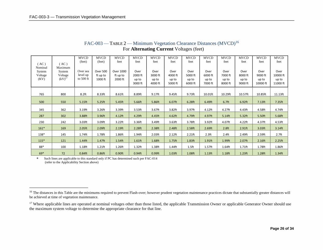
FFAACC--000033 —— TTAABBLLEE 22 —— MMiinniimmuumm VVeeggeettaattiioonn CClleeaarraannccee DDiissttaanncceess ((MMVVCCDD))1166 For Alternating Current Voltages (feet)
( AC ) Nominal
System
Voltage
(KV)
( AC ) Maximum
System
Voltage
(kV)17
MVCD
(feet)
MVCD
(feet)
MVCD
feet
MVCD
feet
MVCD
feet
MVCD
feet
MVCD
feet
MVCD
feet
MVCD
feet
MVCD
feet
MVCD
feet
MVCD
feet
Over sea level up
to 500 ft
Over 500 ft up to 1000 ft
Over 1000 ft up to 2000 ft
Over 2000 ft up to
3000 ft
Over 3000 ft up to
4000 ft
Over 4000 ft up to
5000 ft
Over 5000 ft up to
6000 ft
Over 6000 ft up to
7000 ft
Over 7000 ft up to
8000 ft
Over 8000 ft up to
9000 ft
Over 9000 ft up to
10000 ft
Over 10000 ft
up to 11000 ft
765 800 8.2ft 8.33ft 8.61ft 8.89ft 9.17ft 9.45ft 9.73ft 10.01ft 10.29ft 10.57ft 10.85ft 11.13ft
500 550 5.15ft 5.25ft 5.45ft 5.66ft 5.86ft 6.07ft 6.28ft 6.49ft 6.7ft 6.92ft 7.13ft 7.35ft
345 362 3.19ft 3.26ft 3.39ft 3.53ft 3.67ft 3.82ft 3.97ft 4.12ft 4.27ft 4.43ft 4.58ft 4.74ft
287 302 3.88ft 3.96ft 4.12ft 4.29ft 4.45ft 4.62ft 4.79ft 4.97ft 5.14ft 5.32ft 5.50ft 5.68ft
230 242 3.03ft 3.09ft 3.22ft 3.36ft 3.49ft 3.63ft 3.78ft 3.92ft 4.07ft 4.22ft 4.37ft 4.53ft
161* 169 2.05ft 2.09ft 2.19ft 2.28ft 2.38ft 2.48ft 2.58ft 2.69ft 2.8ft 2.91ft 3.03ft 3.14ft
138* 145 1.74ft 1.78ft 1.86ft 1.94ft 2.03ft 2.12ft 2.21ft 2.3ft 2.4ft 2.49ft 2.59ft 2.7ft
115* 121 1.44ft 1.47ft 1.54ft 1.61ft 1.68ft 1.75ft 1.83ft 1.91ft 1.99ft 2.07ft 2.16ft 2.25ft
88* 100 1.18ft 1.21ft 1.26ft 1.32ft 1.38ft 1.44ft 1.5ft 1.57ft 1.64ft 1.71ft 1.78ft 1.86ft
69* 72 0.84ft 0.86ft 0.90ft 0.94ft 0.99ft 1.03ft 1.08ft 1.13ft 1.18ft 1.23ft 1.28ft 1.34ft
Such lines are applicable to this standard only if PC has determined such per FAC-014 (refer to the Applicability Section above)
16 The distances in this Table are the minimums required to prevent Flash-over; however prudent vegetation maintenance practices dictate that substantially greater distances will
be achieved at time of vegetation maintenance.
17 Where applicable lines are operated at nominal voltages other than those listed, the applicable Transmission Owner or applicable Generator Owner should use
the maximum system voltage to determine the appropriate clearance for that line.

FAC-003-3 — Transmission Vegetation Management
Page 27 of 34
TTAABBLLEE 22 ((CCOONNTT)) —— MMiinniimmuumm VVeeggeettaattiioonn CClleeaarraannccee DDiissttaanncceess ((MMVVCCDD))77 For Alternating Current Voltages (meters)
( AC )
Nominal System
Voltage
(KV)
( AC ) Maximum
System
Voltage
(kV)8
MVCD
meters
MVCD
meters
MVCD
meters
MVCD
meters
MVCD
meters
MVCD
meters
MVCD
meters
MVCD
meters
MVCD
meters
MVCD
meters
MVCD
meters
MVCD
meters
Over sea level up to 152.4 m
Over 152.4 m up to 304.8 m
Over 304.8 m up to 609.6m
Over 609.6m up to 914.4m
Over 914.4m up
to 1219.2m
Over 1219.2m
up to 1524m
Over 1524 m up to 1828.8
m
Over 1828.8m
up to 2133.6m
Over 2133.6m
up to 2438.4m
Over 2438.4m up to 2743.2m
Over 2743.2m up
to 3048m
Over 3048m up
to 3352.8m
765 800 2.49m 2.54m 2.62m 2.71m 2.80m 2.88m 2.97m 3.05m 3.14m 3.22m 3.31m 3.39m
500 550 1.57m 1.6m 1.66m 1.73m 1.79m 1.85m 1.91m 1.98m 2.04m 2.11m 2.17m 2.24m
345 362 0.97m 0.99m 1.03m 1.08m 1.12m 1.16m 1.21m 1.26m 1.30m 1.35m 1.40m 1.44m
287 302 1.18m 0.88m 1.26m 1.31m 1.36m 1.41m 1.46m 1.51m 1.57m 1.62m 1.68m 1.73m
230 242 0.92m 0.94m 0.98m 1.02m 1.06m 1.11m 1.15m 1.19m 1.24m 1.29m 1.33m 1.38m
161* 169 0.62m 0.64m 0.67m 0.69m 0.73m 0.76m 0.79m 0.82m 0.85m 0.89m 0.92m 0.96m
138* 145 0.53m 0.54m 0.57m 0.59m 0.62m 0.65m 0.67m 0.70m 0.73m 0.76m 0.79m 0.82m
115* 121 0.44m 0.45m 0.47m 0.49m 0.51m 0.53m 0.56m 0.58m 0.61m 0.63m 0.66m 0.69m
88* 100 0.36m 0.37m 0.38m 0.40m 0.42m 0.44m 0.46m 0.48m 0.50m 0.52m 0.54m 0.57m
69* 72 0.26m 0.26m 0.27m 0.29m 0.30m 0.31m 0.33m 0.34m 0.36m 0.37m 0.39m 0.41m
Such lines are applicable to this standard only if PC has determined such per FAC-014 (refer to the Applicability Section above)

FAC-003-3 — Transmission Vegetation Management
Page 28 of 34
TTAABBLLEE 22 ((CCOONNTT)) —— MMiinniimmuumm VVeeggeettaattiioonn CClleeaarraannccee DDiissttaanncceess ((MMVVCCDD))77 For Direct Current Voltages feet (meters)
( DC )
Nominal Pole to
Ground
Voltage (kV)
MVCD meters
MVCD meters
MVCD meters
MVCD meters
MVCD meters
MVCD meters
MVCD meters
MVCD meters
MVCD meters
MVCD meters
MVCD meters
MVCD meters
Over sea level up to
500 ft
Over 500 ft up to 1000 ft
Over 1000 ft up to 2000 ft
Over 2000 ft up to 3000 ft
Over 3000 ft up to 4000 ft
Over 4000 ft up to 5000 ft
Over 5000 ft up to 6000 ft
Over 6000 ft up to 7000 ft
Over 7000 ft up to 8000 ft
Over 8000 ft up to 9000 ft
Over 9000 ft up to 10000 ft
Over 10000 ft up to 11000 ft
(Over sea level up to 152.4 m)
(Over 152.4 m
up to 304.8 m
(Over 304.8 m
up to 609.6m)
(Over 609.6m up to 914.4m
(Over 914.4m up
to 1219.2m
(Over 1219.2m
up to 1524m
(Over 1524 m up to 1828.8
m)
(Over 1828.8m
up to 2133.6m)
(Over 2133.6m
up to 2438.4m)
(Over 2438.4m
up to 2743.2m)
(Over 2743.2m
up to 3048m)
(Over 3048m up
to 3352.8m)
±750 14.12ft (4.30m)
14.31ft (4.36m)
14.70ft (4.48m)
15.07ft (4.59m)
15.45ft (4.71m)
15.82ft (4.82m)
16.2ft (4.94m)
16.55ft (5.04m)
16.91ft (5.15m)
17.27ft (5.26m)
17.62ft (5.37m)
17.97ft (5.48m)
±600 10.23ft (3.12m)
10.39ft (3.17m)
10.74ft (3.26m)
11.04ft (3.36m)
11.35ft (3.46m)
11.66ft (3.55m)
11.98ft (3.65m)
12.3ft (3.75m)
12.62ft (3.85m)
12.92ft (3.94m)
13.24ft (4.04m)
13.54ft (4.13m)
±500 8.03ft
(2.45m) 8.16ft
(2.49m) 8.44ft
(2.57m) 8.71ft
(2.65m) 8.99ft
(2.74m) 9.25ft
(2.82m) 9.55ft
(2.91m) 9.82ft
(2.99m) 10.1ft
(3.08m) 10.38ft (3.16m)
10.65ft (3.25m)
10.92ft (3.33m)
±400 6.07ft
(1.85m) 6.18ft
(1.88m) 6.41ft
(1.95m) 6.63ft
(2.02m) 6.86ft
(2.09m) 7.09ft
(2.16m) 7.33ft
(2.23m) 7.56ft
(2.30m) 7.80ft
(2.38m) 8.03ft
(2.45m) 8.27ft
(2.52m) 8.51ft
(2.59m)
±250 3.50ft
(1.07m) 3.57ft
(1.09m) 3.72ft
(1.13m) 3.87ft
(1.18m) 4.02ft
(1.23m) 4.18ft
(1.27m) 4.34ft
(1.32m) 4.5ft
(1.37m) 4.66ft
(1.42m) 4.83ft
(1.47m) 5.00ft
(1.52m) 5.17ft
(1.58m)

FAC-003-3 — Transmission Vegetation Management
Page 29 of 34
Notes:
The SDT determined that the use of IEEE 516-2003 in version 1 of FAC-003 was a
misapplication. The SDT consulted specialists who advised that the Gallet Equation would be a
technically justified method. The explanation of why the Gallet approach is more appropriate is
explained in the paragraphs below.
The drafting team sought a method of establishing minimum clearance distances that uses
realistic weather conditions and realistic maximum transient over-voltages factors for in-service
transmission lines.
The SDT considered several factors when looking at changes to the minimum vegetation to
conductor distances in FAC-003-1:
avoid the problem associated with referring to tables in another standard (IEEE-516-
2003)
transmission lines operate in non-laboratory environments (wet conditions)
transient over-voltage factors are lower for in-service transmission lines than for
inadvertently re-energized transmission lines with trapped charges.
FAC-003-1 uses the minimum air insulation distance (MAID) without tools formula provided in
IEEE 516-2003 to determine the minimum distance between a transmission line conductor and
vegetation. The equations and methods provided in IEEE 516 were developed by an IEEE Task
Force in 1968 from test data provided by thirteen independent laboratories. The distances
provided in IEEE 516 Tables 5 and 7 are based on the withstand voltage of a dry rod-rod air gap,
or in other words, dry laboratory conditions. Consequently, the validity of using these distances
in an outside environment application has been questioned.
FAC-003-01 allowed Transmission Owners to use either Table 5 or Table 7 to establish the
minimum clearance distances. Table 7 could be used if the Transmission Owner knew the
maximum transient over-voltage factor for its system. Otherwise, Table 5 would have to be
used. Table 5 represented minimum air insulation distances under the worst possible case for
transient over-voltage factors. These worst case transient over-voltage factors were as follows:
3.5 for voltages up to 362 kV phase to phase; 3.0 for 500 - 550 kV phase to phase; and 2.5 for
765 to 800 kV phase to phase. These worst case over-voltage factors were also a cause for
concern in this particular application of the distances.
In general, the worst case transient over-voltages occur on a transmission line that is
inadvertently re-energized immediately after the line is de-energized and a trapped charge is still
present. The intent of FAC-003 is to keep a transmission line that is in service from becoming
de-energized (i.e. tripped out) due to spark-over from the line conductor to nearby vegetation.
Thus, the worst case transient overvoltage assumptions are not appropriate for this application.
Rather, the appropriate over voltage values are those that occur only while the line is energized.
Typical values of transient over-voltages of in-service lines, as such, are not readily available in
the literature because they are negligible compared with the maximums. A conservative value
for the maximum transient over-voltage that can occur anywhere along the length of an in-

FAC-003-3 — Transmission Vegetation Management
Page 30 of 34
service ac line is approximately 2.0 per unit. This value is a conservative estimate of the
transient over-voltage that is created at the point of application (e.g. a substation) by switching a
capacitor bank without pre-insertion devices (e.g. closing resistors). At voltage levels where
capacitor banks are not very common (e.g. Maximum System Voltage of 362 kV), the maximum
transient over-voltage of an in-service ac line are created by fault initiation on adjacent ac lines
and shunt reactor bank switching. These transient voltages are usually 1.5 per unit or less.
Even though these transient over-voltages will not be experienced at locations remote from the
bus at which they are created, in order to be conservative, it is assumed that all nearby ac lines
are subjected to this same level of over-voltage. Thus, a maximum transient over-voltage factor
of 2.0 per unit for transmission lines operated at 302 kV and below is considered to be a realistic
maximum in this application. Likewise, for ac transmission lines operated at Maximum System
Voltages of 362 kV and above a transient over-voltage factor of 1.4 per unit is considered a
realistic maximum.
The Gallet Equations are an accepted method for insulation coordination in tower design. These
equations are used for computing the required strike distances for proper transmission line
insulation coordination. They were developed for both wet and dry applications and can be used
with any value of transient over-voltage factor. The Gallet Equation also can take into account
various air gap geometries. This approach was used to design the first 500 kV and 765 kV lines
in North America.
If one compares the MAID using the IEEE 516-2003 Table 7 (table D.5 for English values) with
the critical spark-over distances computed using the Gallet wet equations, for each of the
nominal voltage classes and identical transient over-voltage factors, the Gallet equations yield a
more conservative (larger) minimum distance value.
Distances calculated from either the IEEE 516 (dry) formulas or the Gallet “wet” formulas are
not vastly different when the same transient overvoltage factors are used; the “wet” equations
will consistently produce slightly larger distances than the IEEE 516 equations when the same
transient overvoltage is used. While the IEEE 516 equations were only developed for dry
conditions the Gallet equations have provisions to calculate spark-over distances for both wet
and dry conditions.
While EPRI is currently trying to establish empirical data for spark-over distances to live
vegetation, there are no spark-over formulas currently derived expressly for vegetation to
conductor minimum distances. Therefore the SDT chose a proven method that has been used in
other EHV applications. The Gallet equations relevance to wet conditions and the selection of a
Transient Overvoltage Factor that is consistent with the absence of trapped charges on an in-
service transmission line make this methodology a better choice.
The following table is an example of the comparison of distances derived from IEEE 516 and the
Gallet equations.

FAC-003-3 — Transmission Vegetation Management
Page 31 of 34
Comparison of spark-over distances computed using Gallet wet equations vs.
IEEE 516-2003 MAID distances
Table 7
(Table D.5 for feet)
( AC ) ( AC ) Transient Clearance (ft.) IEEE 516-2003
Nom System Max System Over-voltage Gallet (wet) MAID (ft)
Voltage (kV) Voltage (kV) Factor (T) @ Alt. 3000 feet @ Alt. 3000 feet
765 800 2.0 14.36 13.95
500 550 2.4 11.0 10.07
345 362 3.0 8.55 7.47
230 242 3.0 5.28 4.2
115 121 3.0 2.46 2.1
Rationale:
During development of this standard, text boxes were embedded within the standard to explain
the rationale for various parts of the standard. Upon BOT approval, the text from the rationale
text boxes was moved to this section.
Rationale for Applicability (section 4.2.4):
The areas excluded in 4.2.4 were excluded based on comments from industry for reasons
summarized as follows: 1) There is a very low risk from vegetation in this area. Based on an
informal survey, no TOs reported such an event. 2) Substations, switchyards, and stations have
many inspection and maintenance activities that are necessary for reliability. Those existing
process manage the threat. As such, the formal steps in this standard are not well suited for this
environment. 3) Specifically addressing the areas where the standard does and does not apply
makes the standard clearer.
Rationale for Applicability (section 4.3):
Within the text of NERC Reliability Standard FAC-003-3, “transmission line(s) and “applicable
line(s) can also refer to the generation Facilities as referenced in 4.3 and its subsections.
Rationale for R1 and R2:
Lines with the highest significance to reliability are covered in R1; all other lines are covered in
R2.
Rationale for the types of failure to manage vegetation which are listed in order of increasing
degrees of severity in non-compliant performance as it relates to a failure of an applicable
Transmission Owner's or applicable Generator Owner’s vegetation maintenance program:

FAC-003-3 — Transmission Vegetation Management
Page 32 of 34
1. This management failure is found by routine inspection or Fault event investigation, and is
normally symptomatic of unusual conditions in an otherwise sound program.
2. This management failure occurs when the height and location of a side tree within the ROW is
not adequately addressed by the program.
3. This management failure occurs when side growth is not adequately addressed and may be
indicative of an unsound program.
4. This management failure is usually indicative of a program that is not addressing the most
fundamental dynamic of vegetation management, (i.e. a grow-in under the line). If this type of
failure is pervasive on multiple lines, it provides a mechanism for a Cascade.
Rationale for R3:
The documentation provides a basis for evaluating the competency of the applicable
Transmission Owner’s or applicable Generator Owner’s vegetation program. There may be
many acceptable approaches to maintain clearances. Any approach must demonstrate that the
applicable Transmission Owner or applicable Generator Owner avoids vegetation-to-wire
conflicts under all Ratings and all Rated Electrical Operating Conditions. See Figure
Rationale for R4:
This is to ensure expeditious communication between the applicable Transmission Owner or
applicable Generator Owner and the control center when a critical situation is confirmed.
Rationale for R5:
Legal actions and other events may occur which result in constraints that prevent the applicable
Transmission Owner or applicable Generator Owner from performing planned vegetation
maintenance work.
In cases where the transmission line is put at potential risk due to constraints, the intent is for the
applicable Transmission Owner and applicable Generator Owner to put interim measures in
place, rather than do nothing.
The corrective action process is not intended to address situations where a planned work
methodology cannot be performed but an alternate work methodology can be used.
Rationale for R6:
Inspections are used by applicable Transmission Owners and applicable Generator Owners to
assess the condition of the entire ROW. The information from the assessment can be used to
determine risk, determine future work and evaluate recently-completed work. This requirement
sets a minimum Vegetation Inspection frequency of once per calendar year but with no more
than 18 months between inspections on the same ROW. Based upon average growth rates across
North America and on common utility practice, this minimum frequency is reasonable.
Transmission Owners should consider local and environmental factors that could warrant more
frequent inspections.

FAC-003-3 — Transmission Vegetation Management
Page 33 of 34
Rationale for R7:
This requirement sets the expectation that the work identified in the annual work plan will be
completed as planned. It allows modifications to the planned work for changing conditions,
taking into consideration anticipated growth of vegetation and all other environmental factors,
provided that those modifications do not put the transmission system at risk of a vegetation
encroachment.
Version History
Version Date Action Change Tracking
1 TBA 1. Added “Standard Development
Roadmap.”
2. Changed “60” to “Sixty” in section
A, 5.2.
3. Added “Proposed Effective Date:
April 7, 2006” to footer.
4. Added “Draft 3: November 17,
2005” to footer.
01/20/06
1 April 4, 2007 Regulatory Approval - Effective Date New
2 November 3,
2011
Adopted by the NERC Board of
Trustees
2 March 21,
2013
FERC Order issued approving FAC-
003-2
2 May 9, 2013 Board of Trustees adopted the
modification of the VRF for
Requirement
R2 of FAC-003-2 by raising the VRF
from
“Medium” to “High.”
3 May 9, 2012 FAC-003-3 adopted by Board of
Trustees
3 September 19,
2013
A FERC order was issued on September
19, 2013, approving FAC-003-3. This
standard becomes enforceable on July 1,
2014 for Transmission Owners. For
Generator Owners, R3 becomes
enforceable on January 1, 2015 and all
other requirements (R1, R2, R4, R5, R6,
and R7) will become enforceable on
January 1, 2016.
3 November 22,
2013
Updated the VRF for R2 from
“Medium” to “High” per a Final Rule
issued by FERC

FAC-003-3 — Transmission Vegetation Management
Page 34 of 34
3 July 30, 2014 Transferred the effective dates section
from FAC-003-2 (for Transmission
Owners) into FAC-003-3, per the FAC-
003-3 implementation plan