Effective August 2018 Application note 3148 … · 3 Application Note 3148 Effective August 2018...
24
Quik-Spec Coordination Panelboard (QSCP) BUSSMANN SERIES Application note 3148 Effective August 2018 Supersedes September 2017 Introduction 2 Features/benefits 2 QSCP Overview 3-4 Selective coordination made easy 5 Comparing fusible branch circuit panelboards 6 QSCP Short-Circuit Current Ratings (SCCRs) 7-8 How to achieve selective coordination 9-10 Selective coordination using fuses 11 Selective coordination using upstream Eaton thermal magnetic circuit breakers 12 240, 480, 600 Vac Quick Pick tables 13 240 Vac Circuit breaker tables 14 480 Vac Circuit breaker tables 15 600 Vac Circuit breaker tables 16 QSCP applications and fuse sizing Lighting circuits 17 Motor circuits 18 Transformers 19 CUBEFuse sizing for motors (115-575 Vac) 20 Protecting leads fed from Uninterruptable Power Supplies (UPS) 21 Surge Protective Devices (SPDs) 22 Reference materials 23 Contents Description Page Description Page
Transcript of Effective August 2018 Application note 3148 … · 3 Application Note 3148 Effective August 2018...
Quik-Spec Coordination Panelboard (QSCP)
BUSSMANNSERIESApplication note 3148
Effective August 2018Supersedes September 2017
Introduction . . . . . . . . . . . . . . . . . . . . . . . . . . . . . . 2Features/benefits . . . . . . . . . . . . . . . . . . . . . . . . . . 2QSCP Overview . . . . . . . . . . . . . . . . . . . . . . . . . 3-4Selective coordination made easy . . . . . . . . . . . . . 5Comparing fusible branch circuit panelboards . . . . 6QSCP Short-Circuit Current Ratings (SCCRs) . . 7-8How to achieve selective coordination . . . . . . 9-10Selective coordination using fuses . . . . . . . . . . . 11Selective coordination using upstream Eaton thermal magnetic circuit breakers . . . . . . . . . . . . 12 240, 480, 600 Vac Quick Pick tables . . . . . . . . 13 240 Vac Circuit breaker tables . . . . . . . . . . . . . 14 480 Vac Circuit breaker tables . . . . . . . . . . . . . 15 600 Vac Circuit breaker tables . . . . . . . . . . . . . 16
QSCP applications and fuse sizing Lighting circuits . . . . . . . . . . . . . . . . . . . . . . . . 17 Motor circuits . . . . . . . . . . . . . . . . . . . . . . . . . 18 Transformers . . . . . . . . . . . . . . . . . . . . . . . . . . 19 CUBEFuse sizing for motors (115-575 Vac) . . . 20Protecting leads fed from Uninterruptable Power Supplies (UPS) . . . . . . . . . . . . . . . . . . . . . 21Surge Protective Devices (SPDs) . . . . . . . . . . . . 22Reference materials . . . . . . . . . . . . . . . . . . . . . . 23
ContentsDescription Page Description Page
2
Application Note 3148Effective August 2018
Quik-Spec Coordination Panelboard (QSCP)application note
Eaton.com/bussmannseries
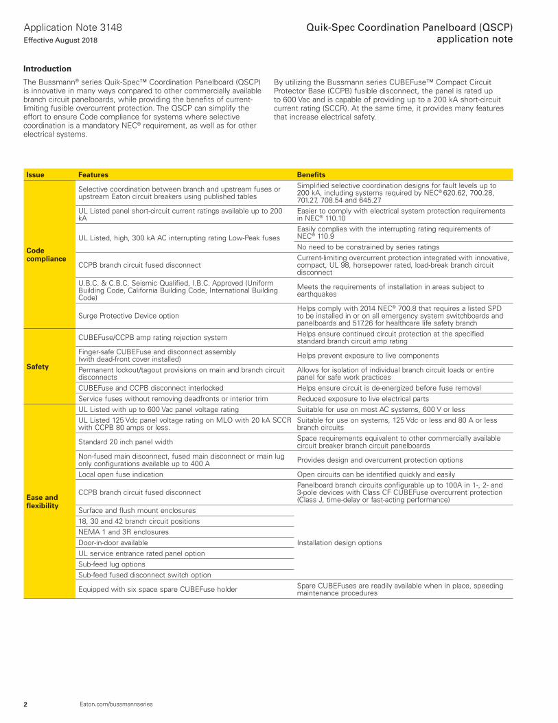
By utilizing the Bussmann series CUBEFuse™ Compact Circuit Protector Base (CCPB) fusible disconnect, the panel is rated up to 600 Vac and is capable of providing up to a 200 kA short-circuit current rating (SCCR) . At the same time, it provides many features that increase electrical safety .
Introduction
The Bussmann® series Quik-Spec™ Coordination Panelboard (QSCP) is innovative in many ways compared to other commercially available branch circuit panelboards, while providing the benefits of current-limiting fusible overcurrent protection . The QSCP can simplify the effort to ensure Code compliance for systems where selective coordination is a mandatory NEC® requirement, as well as for other electrical systems .
Issue Features Benefits
Code compliance
Selective coordination between branch and upstream fuses or upstream Eaton circuit breakers using published tables
Simplified selective coordination designs for fault levels up to 200 kA, including systems required by NEC® 620 .62, 700 .28, 701 .27, 708 .54 and 645 .27
UL Listed panel short-circuit current ratings available up to 200 kA
Easier to comply with electrical system protection requirements in NEC® 110 .10
UL Listed, high, 300 kA AC interrupting rating Low-Peak fusesEasily complies with the interrupting rating requirements of NEC® 110 .9No need to be constrained by series ratings
CCPB branch circuit fused disconnectCurrent-limiting overcurrent protection integrated with innovative, compact, UL 98, horsepower rated, load-break branch circuit disconnect
U .B .C . & C .B .C . Seismic Qualified, I .B .C . Approved (Uniform Building Code, California Building Code, International Building Code)
Meets the requirements of installation in areas subject to earthquakes
Surge Protective Device optionHelps comply with 2014 NEC® 700 .8 that requires a listed SPD to be installed in or on all emergency system switchboards and panelboards and 517 .26 for healthcare life safety branch
Safety
CUBEFuse/CCPB amp rating rejection system Helps ensure continued circuit protection at the specified standard branch circuit amp rating
Finger-safe CUBEFuse and disconnect assembly (with dead-front cover installed) Helps prevent exposure to live components
Permanent lockout/tagout provisions on main and branch circuit disconnects
Allows for isolation of individual branch circuit loads or entire panel for safe work practices
CUBEFuse and CCPB disconnect interlocked Helps ensure circuit is de-energized before fuse removalService fuses without removing deadfronts or interior trim Reduced exposure to live electrical parts
Ease and flexibility
UL Listed with up to 600 Vac panel voltage rating Suitable for use on most AC systems, 600 V or lessUL Listed 125 Vdc panel voltage rating on MLO with 20 kA SCCR with CCPB 80 amps or less .
Suitable for use on systems, 125 Vdc or less and 80 A or less branch circuits
Standard 20 inch panel width Space requirements equivalent to other commercially available circuit breaker branch circuit panelboards
Non-fused main disconnect, fused main disconnect or main lug only configurations available up to 400 A Provides design and overcurrent protection options
Local open fuse indication Open circuits can be identified quickly and easily
CCPB branch circuit fused disconnectPanelboard branch circuits configurable up to 100A in 1-, 2- and 3-pole devices with Class CF CUBEFuse overcurrent protection (Class J, time-delay or fast-acting performance)
Surface and flush mount enclosures
Installation design options
18, 30 and 42 branch circuit positionsNEMA 1 and 3R enclosuresDoor-in-door availableUL service entrance rated panel optionSub-feed lug optionsSub-feed fused disconnect switch option
Equipped with six space spare CUBEFuse holder Spare CUBEFuses are readily available when in place, speeding maintenance procedures
3
Application Note 3148Effective August 2018
Quik-Spec Coordination Panelboard (QSCP)application note
Eaton.com/bussmannseries
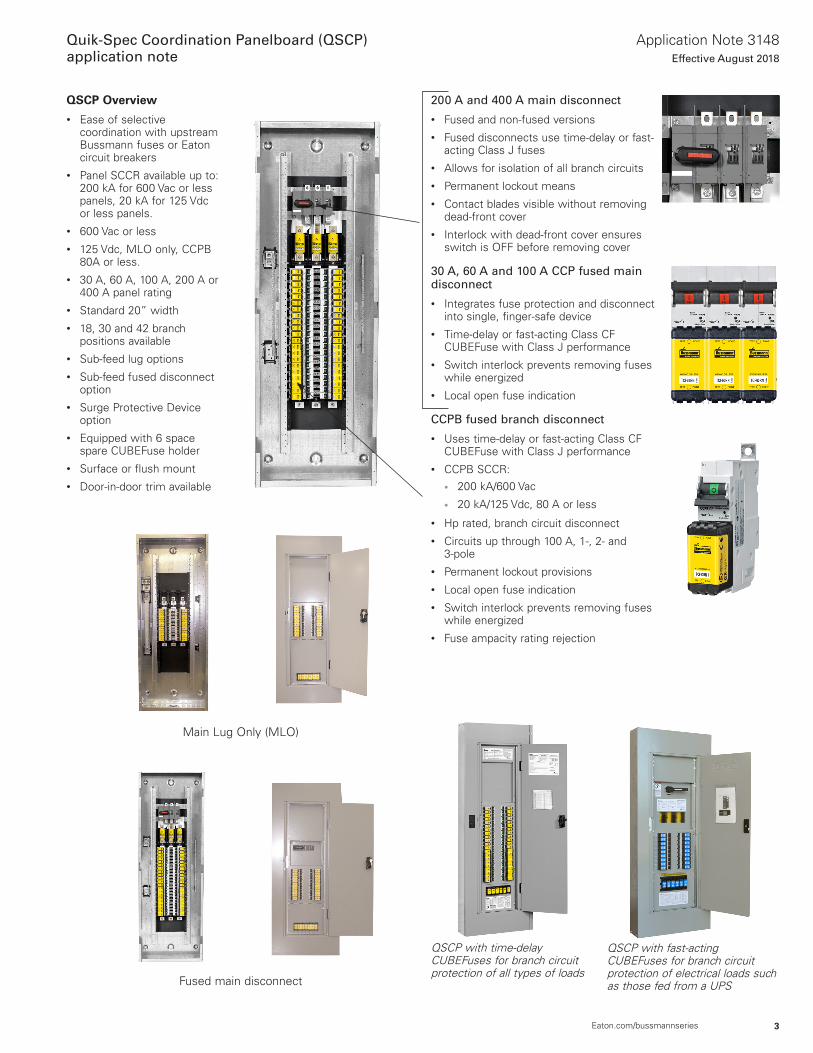
QSCP Overview
• Ease of selective coordination with upstream Bussmann fuses or Eaton circuit breakers
• Panel SCCR available up to: 200 kA for 600 Vac or less panels, 20 kA for 125 Vdc or less panels .
• 600 Vac or less• 125 Vdc, MLO only, CCPB
80A or less .• 30 A, 60 A, 100 A, 200 A or
400 A panel rating• Standard 20” width• 18, 30 and 42 branch
positions available• Sub-feed lug options• Sub-feed fused disconnect
option• Surge Protective Device
option• Equipped with 6 space
spare CUBEFuse holder• Surface or flush mount• Door-in-door trim available
200 A and 400 A main disconnect
• Fused and non-fused versions• Fused disconnects use time-delay or fast-
acting Class J fuses• Allows for isolation of all branch circuits• Permanent lockout means• Contact blades visible without removing
dead-front cover• Interlock with dead-front cover ensures
switch is OFF before removing cover
30 A, 60 A and 100 A CCP fused main disconnect
• Integrates fuse protection and disconnect into single, finger-safe device
• Time-delay or fast-acting Class CF CUBEFuse with Class J performance
• Switch interlock prevents removing fuses while energized
• Local open fuse indication
CCPB fused branch disconnect
• Uses time-delay or fast-acting Class CF CUBEFuse with Class J performance
• CCPB SCCR:• 200 kA/600 Vac
• 20 kA/125 Vdc, 80 A or less
• Hp rated, branch circuit disconnect• Circuits up through 100 A, 1-, 2- and
3-pole• Permanent lockout provisions• Local open fuse indication• Switch interlock prevents removing fuses
while energized• Fuse ampacity rating rejection
Main Lug Only (MLO)
Fused main disconnect
QSCP with time-delay CUBEFuses for branch circuit protection of all types of loads
QSCP with fast-acting CUBEFuses for branch circuit protection of electrical loads such as those fed from a UPS
4
Application Note 3148Effective August 2018
Quik-Spec Coordination Panelboard (QSCP)application note
Eaton.com/bussmannseries
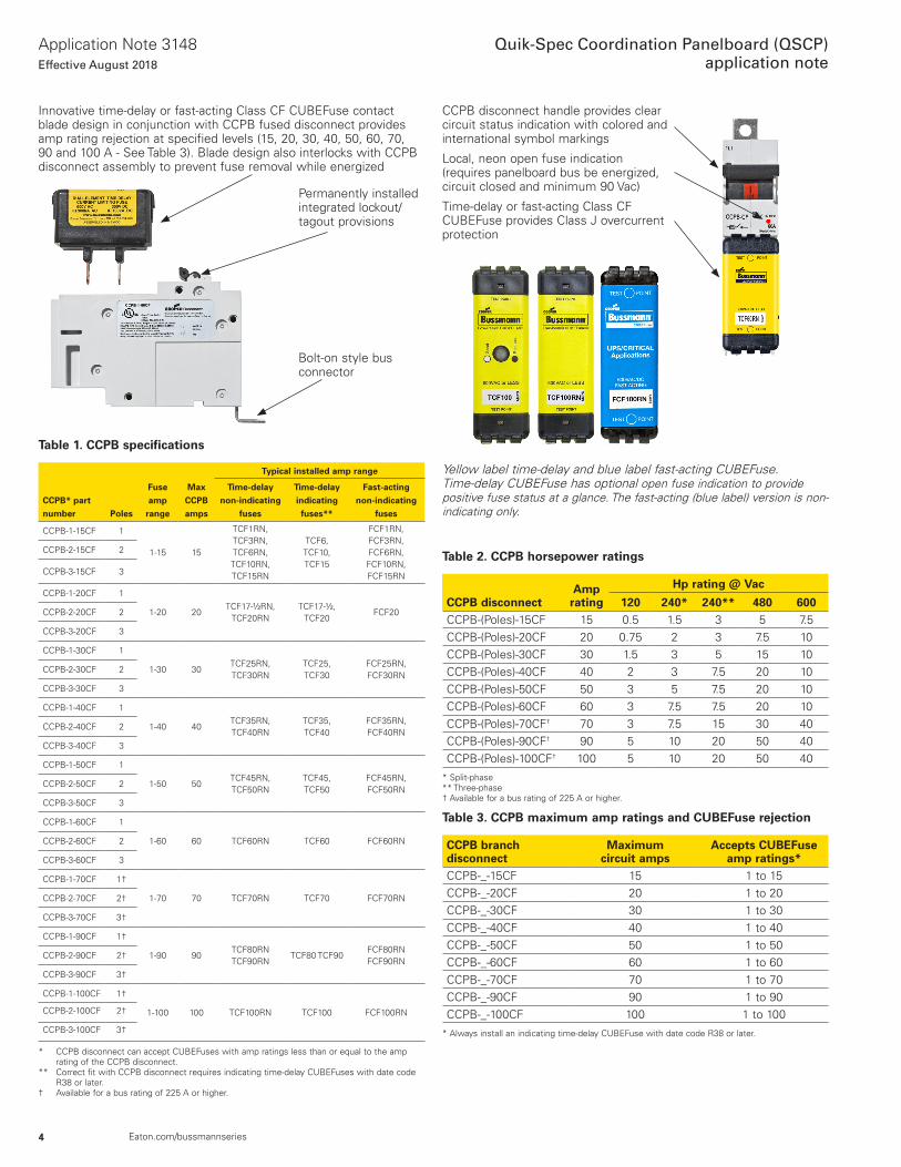
Innovative time-delay or fast-acting Class CF CUBEFuse contact blade design in conjunction with CCPB fused disconnect provides amp rating rejection at specified levels (15, 20, 30, 40, 50, 60, 70, 90 and 100 A - See Table 3) . Blade design also interlocks with CCPB disconnect assembly to prevent fuse removal while energized
CCPB disconnect handle provides clear circuit status indication with colored and international symbol markings
Local, neon open fuse indication (requires panelboard bus be energized, circuit closed and minimum 90 Vac)
Time-delay or fast-acting Class CF CUBEFuse provides Class J overcurrent protection
Table 2. CCPB horsepower ratings
CCPB disconnectAmp
rating
Hp rating @ Vac
120 240* 240** 480 600CCPB-(Poles)-15CF 15 0 .5 1 .5 3 5 7 .5CCPB-(Poles)-20CF 20 0 .75 2 3 7 .5 10CCPB-(Poles)-30CF 30 1 .5 3 5 15 10CCPB-(Poles)-40CF 40 2 3 7 .5 20 10CCPB-(Poles)-50CF 50 3 5 7 .5 20 10CCPB-(Poles)-60CF 60 3 7 .5 7 .5 20 10CCPB-(Poles)-70CF† 70 3 7 .5 15 30 40CCPB-(Poles)-90CF† 90 5 10 20 50 40CCPB-(Poles)-100CF† 100 5 10 20 50 40
* Split-phase** Three-phase† Available for a bus rating of 225 A or higher .
Table 3. CCPB maximum amp ratings and CUBEFuse rejection
CCPB branch disconnect
Maximum circuit amps
Accepts CUBEFuse amp ratings*
CCPB-_-15CF 15 1 to 15CCPB-_-20CF 20 1 to 20CCPB-_-30CF 30 1 to 30CCPB-_-40CF 40 1 to 40CCPB-_-50CF 50 1 to 50CCPB-_-60CF 60 1 to 60CCPB-_-70CF 70 1 to 70CCPB-_-90CF 90 1 to 90CCPB-_-100CF 100 1 to 100
* Always install an indicating time-delay CUBEFuse with date code R38 or later .
Table 1. CCPB specifications
CCPB* part number Poles
Fuse amp
range
Max CCPB amps
Typical installed amp range
Time-delay non-indicating
fuses
Time-delay indicating fuses**
Fast-acting non-indicating
fuses
CCPB-1-15CF 1
1-15 15
TCF1RN, TCF3RN, TCF6RN, TCF10RN, TCF15RN
TCF6, TCF10, TCF15
FCF1RN, FCF3RN, FCF6RN, FCF10RN, FCF15RN
CCPB-2-15CF 2
CCPB-3-15CF 3
CCPB-1-20CF 1
1-20 20TCF17-½RN,
TCF20RNTCF17-½,
TCF20FCF20CCPB-2-20CF 2
CCPB-3-20CF 3
CCPB-1-30CF 1
1-30 30TCF25RN, TCF30RN
TCF25, TCF30
FCF25RN, FCF30RN
CCPB-2-30CF 2
CCPB-3-30CF 3
CCPB-1-40CF 1
1-40 40TCF35RN, TCF40RN
TCF35, TCF40
FCF35RN, FCF40RN
CCPB-2-40CF 2
CCPB-3-40CF 3
CCPB-1-50CF 1
1-50 50TCF45RN, TCF50RN
TCF45, TCF50
FCF45RN, FCF50RN
CCPB-2-50CF 2
CCPB-3-50CF 3
CCPB-1-60CF 1
1-60 60 TCF60RN TCF60 FCF60RNCCPB-2-60CF 2
CCPB-3-60CF 3
CCPB-1-70CF 1†
1-70 70 TCF70RN TCF70 FCF70RNCCPB-2-70CF 2†
CCPB-3-70CF 3†
CCPB-1-90CF 1†
1-90 90TCF80RN TCF90RN
TCF80 TCF90FCF80RN FCF90RN
CCPB-2-90CF 2†
CCPB-3-90CF 3†
CCPB-1-100CF 1†
1-100 100 TCF100RN TCF100 FCF100RNCCPB-2-100CF 2†
CCPB-3-100CF 3†
* CCPB disconnect can accept CUBEFuses with amp ratings less than or equal to the amp rating of the CCPB disconnect .
** Correct fit with CCPB disconnect requires indicating time-delay CUBEFuses with date code R38 or later .
† Available for a bus rating of 225 A or higher .
Permanently installed integrated lockout/tagout provisions
Bolt-on style bus connector
Yellow label time-delay and blue label fast-acting CUBEFuse . Time-delay CUBEFuse has optional open fuse indication to provide positive fuse status at a glance . The fast-acting (blue label) version is non-indicating only .
5
Application Note 3148Effective August 2018
Quik-Spec Coordination Panelboard (QSCP)application note
Eaton.com/bussmannseries
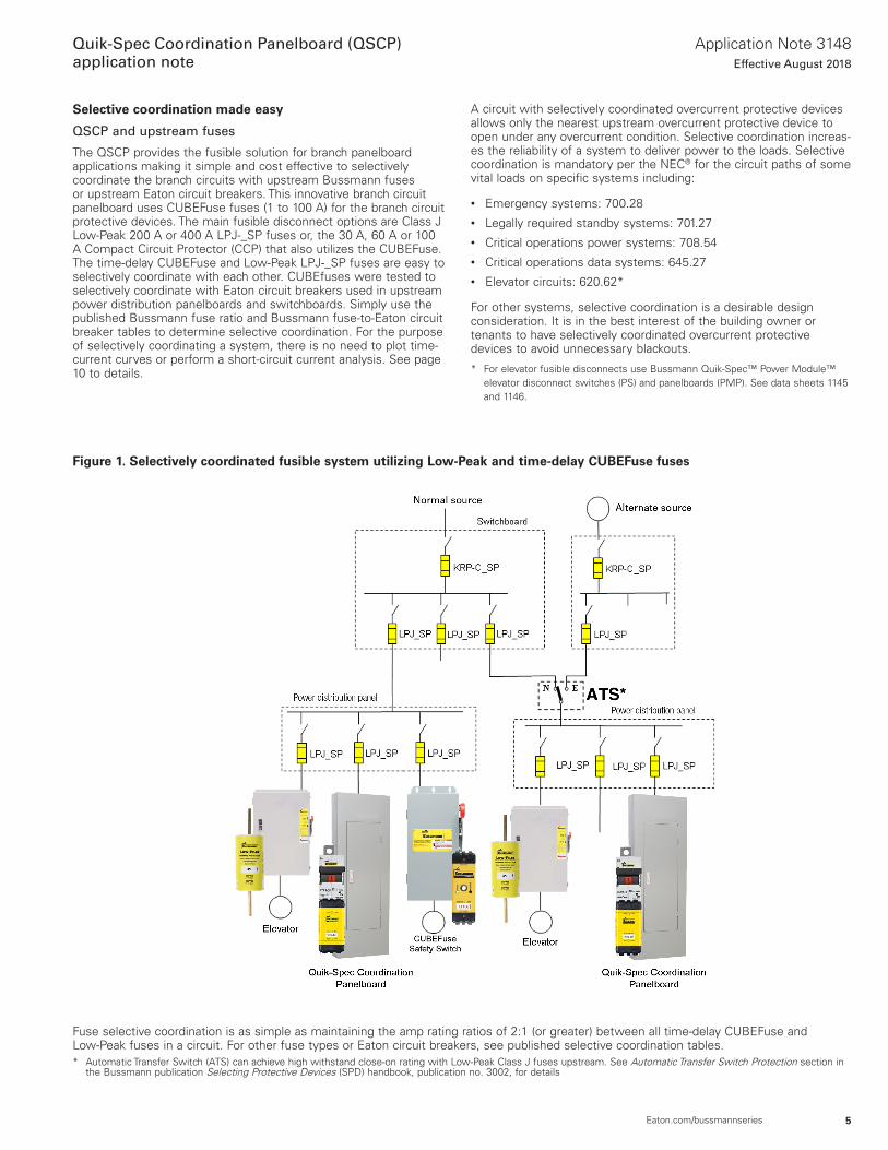
Selective coordination made easy
QSCP and upstream fuses
The QSCP provides the fusible solution for branch panelboard applications making it simple and cost effective to selectively coordinate the branch circuits with upstream Bussmann fuses or upstream Eaton circuit breakers . This innovative branch circuit panelboard uses CUBEFuse fuses (1 to 100 A) for the branch circuit protective devices . The main fusible disconnect options are Class J Low-Peak 200 A or 400 A LPJ-_SP fuses or, the 30 A, 60 A or 100 A Compact Circuit Protector (CCP) that also utilizes the CUBEFuse . The time-delay CUBEFuse and Low-Peak LPJ-_SP fuses are easy to selectively coordinate with each other . CUBEfuses were tested to selectively coordinate with Eaton circuit breakers used in upstream power distribution panelboards and switchboards . Simply use the published Bussmann fuse ratio and Bussmann fuse-to-Eaton circuit breaker tables to determine selective coordination . For the purpose of selectively coordinating a system, there is no need to plot time-current curves or perform a short-circuit current analysis . See page 10 to details .
A circuit with selectively coordinated overcurrent protective devices allows only the nearest upstream overcurrent protective device to open under any overcurrent condition . Selective coordination increas-es the reliability of a system to deliver power to the loads . Selective coordination is mandatory per the NEC® for the circuit paths of some vital loads on specific systems including:
• Emergency systems: 700 .28• Legally required standby systems: 701 .27• Critical operations power systems: 708 .54• Critical operations data systems: 645 .27• Elevator circuits: 620 .62*
For other systems, selective coordination is a desirable design consideration . It is in the best interest of the building owner or tenants to have selectively coordinated overcurrent protective devices to avoid unnecessary blackouts .
* For elevator fusible disconnects use Bussmann Quik-Spec™ Power Module™ elevator disconnect switches (PS) and panelboards (PMP) . See data sheets 1145 and 1146 .
Figure 1. Selectively coordinated fusible system utilizing Low-Peak and time-delay CUBEFuse fuses
Fuse selective coordination is as simple as maintaining the amp rating ratios of 2:1 (or greater) between all time-delay CUBEFuse and Low-Peak fuses in a circuit . For other fuse types or Eaton circuit breakers, see published selective coordination tables .* Automatic Transfer Switch (ATS) can achieve high withstand close-on rating with Low-Peak Class J fuses upstream . See Automatic Transfer Switch Protection section in
the Bussmann publication Selecting Protective Devices (SPD) handbook, publication no . 3002, for details
6
Application Note 3148Effective August 2018
Quik-Spec Coordination Panelboard (QSCP)application note
Eaton.com/bussmannseries
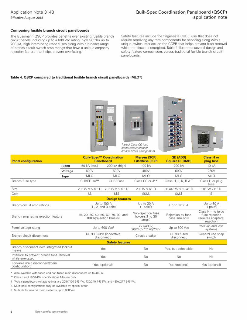
Comparing fusible branch circuit panelboards
The Bussmann QSCP provides benefits over existing fusible branch circuit panels including up to a 600 Vac rating, high SCCRs up to 200 kA, high interrupting rated fuses along with a broader range of branch circuit switch amp ratings that have a unique ampacity rejection feature that helps prevent overfusing .
Safety features include the finger-safe CUBEFuse that does not require removing any trim components for servicing along with a unique switch interlock on the CCPB that helps prevent fuse removal while the circuit is energized . Table 4 illustrates several design and safety feature comparisons versus traditional fusible branch circuit panelboards .
Table 4. QSCP compared to traditional fusible branch circuit panelboards (MLO*)
Panel configurationQuik-Spec™ Coordination
PanelboardMersen (SCP)
Littelfuse (LCP) GE (ADS)
Square D (QMB)Class H or plug fuse
SCCR 50 kA (std .) 200 kA (high) 100 kA 200 kA 10 kA
Voltage 600V 600V 480V 600V 250V
Type MLO MLO MLO MLO MLO
Branch fuse type CUBEFuse™ CUBEFuse Class CC or J** Class H, J, K, R & T Class H or plug fuse
Size 20” W x 5 ¾” D 20” W x 5 ¾” D 28” W x 6” D 36-44” W x 10 .4” D 20” W x 6” DCost $$ $$$ $$$$ $$$$ $
Design features
Branch-circuit amp ratings Up to 100 A (1-, 2- and 3-pole)
Up to 30 A (1-pole2) Up to 1200 A Up to 30 A
(1-pole2)
Branch amp rating rejection feature 15, 20, 30, 40, 50, 60, 70, 90, and 100 A(rejection breaks)
Non-rejection fuse holders(1 to 30
amps)Rejection by fuse
case size only
Class H - no (plug fuse rejection
requires adapters)rejection
Panel voltage rating Up to 600 Vac3 277/480V, 20/240V**120/208V Up to 600 Vac 250 Vac and less
systems
Branch circuit disconnect UL 98 CCPB (innovative disconnect) Circuit breaker UL 98 fused
disconnectGeneral use snap
switch
Safety featuresBranch disconnect with integrated lockout means Yes No Yes, but defeatable No
Interlock to prevent branch fuse removal while energized Yes No No No
Lockable main disconnect(main configuration) Yes (optional) No Yes (optional) Yes (optional)
* Also available with fused and non-fused main disconnects up to 400 A .
** Class J and 120/240V specifications Mersen only .
1 . Typical panelboard voltage ratings are 208Y/120 3-P, 4W, 120/240 1-P, 3W, and 480Y/277 3-P, 4W .
2 . Multi-pole configurations may be available by special order .
3 . Suitable for use on most systems up to 600 Vac .
Typical Class CC fuse holder/circuit breaker branch circuit arrangement
7
Application Note 3148Effective August 2018
Quik-Spec Coordination Panelboard (QSCP)application note
Eaton.com/bussmannseries
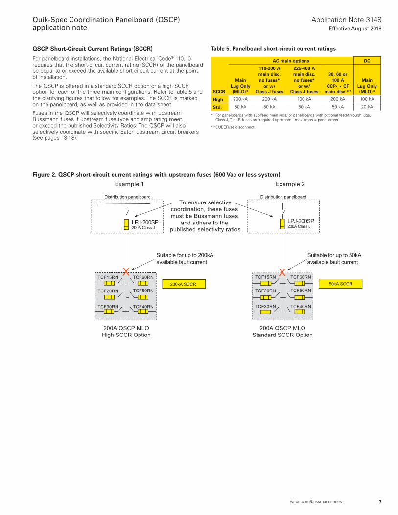
QSCP Short-Circuit Current Ratings (SCCR)
For panelboard installations, the National Electrical Code® 110 .10 requires that the short-circuit current rating (SCCR) of the panelboard be equal to or exceed the available short-circuit current at the point of installation .
The QSCP is offered in a standard SCCR option or a high SCCR option for each of the three main configurations . Refer to Table 5 and the clarifying figures that follow for examples . The SCCR is marked on the panelboard, as well as provided in the data sheet .
Fuses in the QSCP will selectively coordinate with upstream Bussmann fuses if upstream fuse type and amp rating meet or exceed the published Selectivity Ratios . The QSCP will also selectively coordinate with specific Eaton upstream circuit breakers (see pages 13-18) .
Figure 2. QSCP short-circuit current ratings with upstream fuses (600 Vac or less system)
Example 1 Example 2
Table 5. Panelboard short-circuit current ratings
SCCR
AC main options DC
Main Lug Only (MLO)*
110-200 A main disc. no fuses*
or w/ Class J fuses
225-400 A main disc. no fuses*
or w/ Class J fuses
30, 60 or 100 A
CCP-_-_CFmain disc.**
Main Lug Only (MLO)*
High 200 kA 200 kA 100 kA 200 kA 100 kA
Std. 50 kA 50 kA 50 kA 50 kA 20 kA
* For panelboards with sub-feed main lugs, or panelboards with optional feed-through lugs, Class J, T, or R fuses are required upstream - max amps = panel amps .
** CUBEFuse disconnect .
200A QSCP MLO
High SCCR Option
Distribution panelboard
Suitable for up to 200kA
available fault current
LPJ-200SP200A Class J
To ensure selective
coordination, these fuses
must be Bussmann fuses
and adhere to the
published selectivity ratios
200kA SCCR
TCF15RNX X
Distribution panelboard
LPJ-200SP200A Class J
Suitable for up to 50kA
available fault current
50kA SCCR
200A QSCP MLO
Standard SCCR Option
TCF20RN
TCF30RN TCF40RN
TCF50RN
TCF60RN TCF15RN
TCF20RN
TCF30RN TCF40RN
TCF50RN
TCF60RN
8
Application Note 3148Effective August 2018
Quik-Spec Coordination Panelboard (QSCP)application note
Eaton.com/bussmannseries
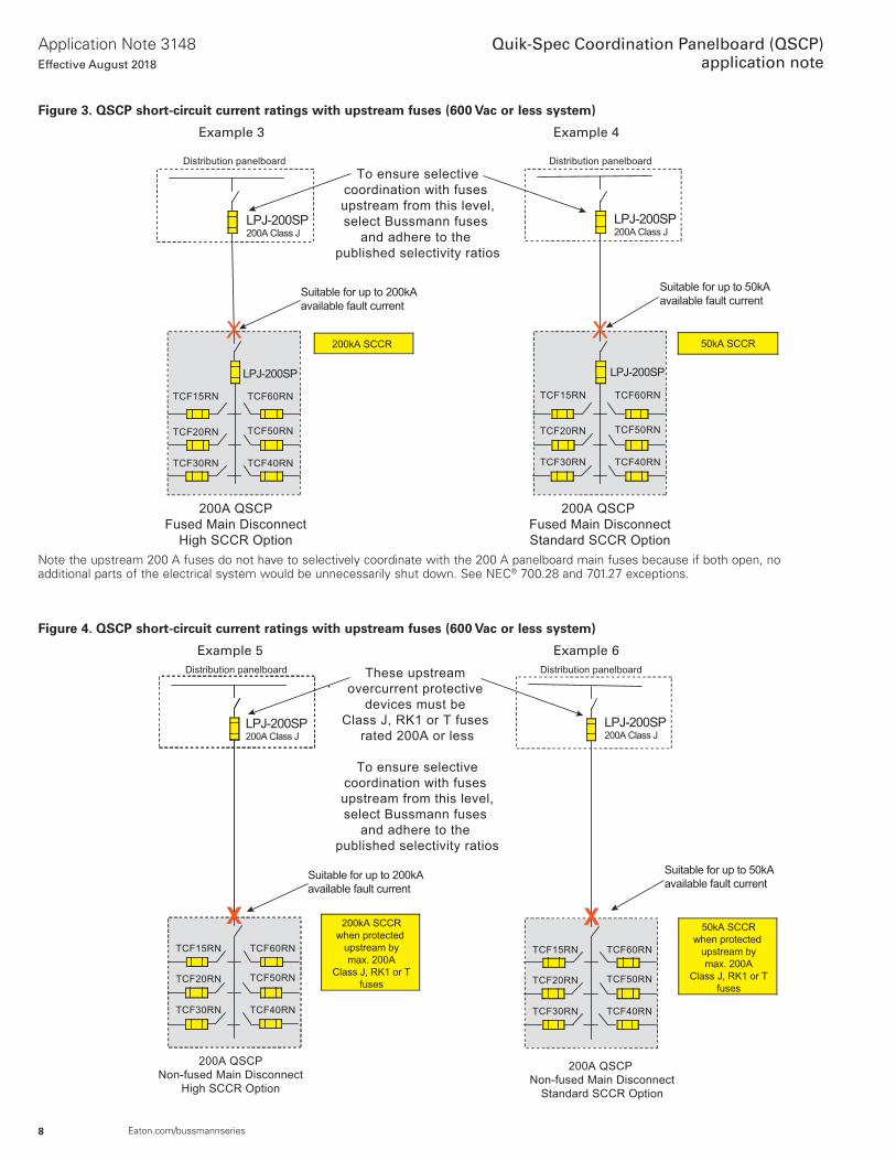
Figure 3. QSCP short-circuit current ratings with upstream fuses (600 Vac or less system)
Example 3 Example 4
Figure 4. QSCP short-circuit current ratings with upstream fuses (600 Vac or less system)
Example 5 Example 6
Note the upstream 200 A fuses do not have to selectively coordinate with the 200 A panelboard main fuses because if both open, no additional parts of the electrical system would be unnecessarily shut down . See NEC® 700 .28 and 701 .27 exceptions .
XX
Distribution panelboard Distribution panelboard
200A QSCP
Fused Main Disconnect
High SCCR Option
Suitable for up to 200kA
available fault current
LPJ-200SP200A Class J
To ensure selective
coordination with fuses
upstream from this level,
select Bussmann fuses
and adhere to the
published selectivity ratios
200kA SCCR
TCF15RN
LPJ-200SP
50kA SCCR
200A QSCP
Fused Main Disconnect
Standard SCCR Option
TCF20RN
TCF30RN TCF40RN
TCF50RN
TCF60RN
Suitable for up to 50kA
available fault current
LPJ-200SP200A Class J
TCF15RN
TCF20RN
TCF30RN TCF40RN
TCF50RN
TCF60RN
LPJ-200SP
XX X
Distribution panelboard Distribution panelboard
200A QSCP
Non-fused Main Disconnect
High SCCR Option
Suitable for up to 200kA
available fault current
LPJ-200SP200A Class J
These upstream
overcurrent protective
devices must be
Class J, RK1 or T fuses
rated 200A or less
To ensure selective
coordination with fuses
upstream from this level,
select Bussmann fuses
and adhere to the
published selectivity ratios
200kA SCCR
when protected
upstream by
max. 200A
Class J, RK1 or T
fuses
TCF15RN
200A QSCP
Non-fused Main Disconnect
Standard SCCR Option
TCF20RN
TCF30RN TCF40RN
TCF50RN
TCF60RN
Suitable for up to 50kA
available fault current
LPJ-200SP200A Class J
50kA SCCR
when protected
upstream by
max. 200A
Class J, RK1 or T
fuses
TCF15RN
TCF20RN
TCF30RN TCF40RN
TCF50RN
TCF60RN
9
Application Note 3148Effective August 2018
Quik-Spec Coordination Panelboard (QSCP)application note
Eaton.com/bussmannseries
How to achieve selective coordination
The QSCP saves the designer time and provides an easy means to selectively coordinate lighting and other branch circuits with upstream Bussmann fuses or Eaton circuit breakers .
Selective coordination increases the reliability of an electrical system to provide availability of power to vital loads .
For selective coordination with upstream Eaton circuit breakers, go to page 12 .
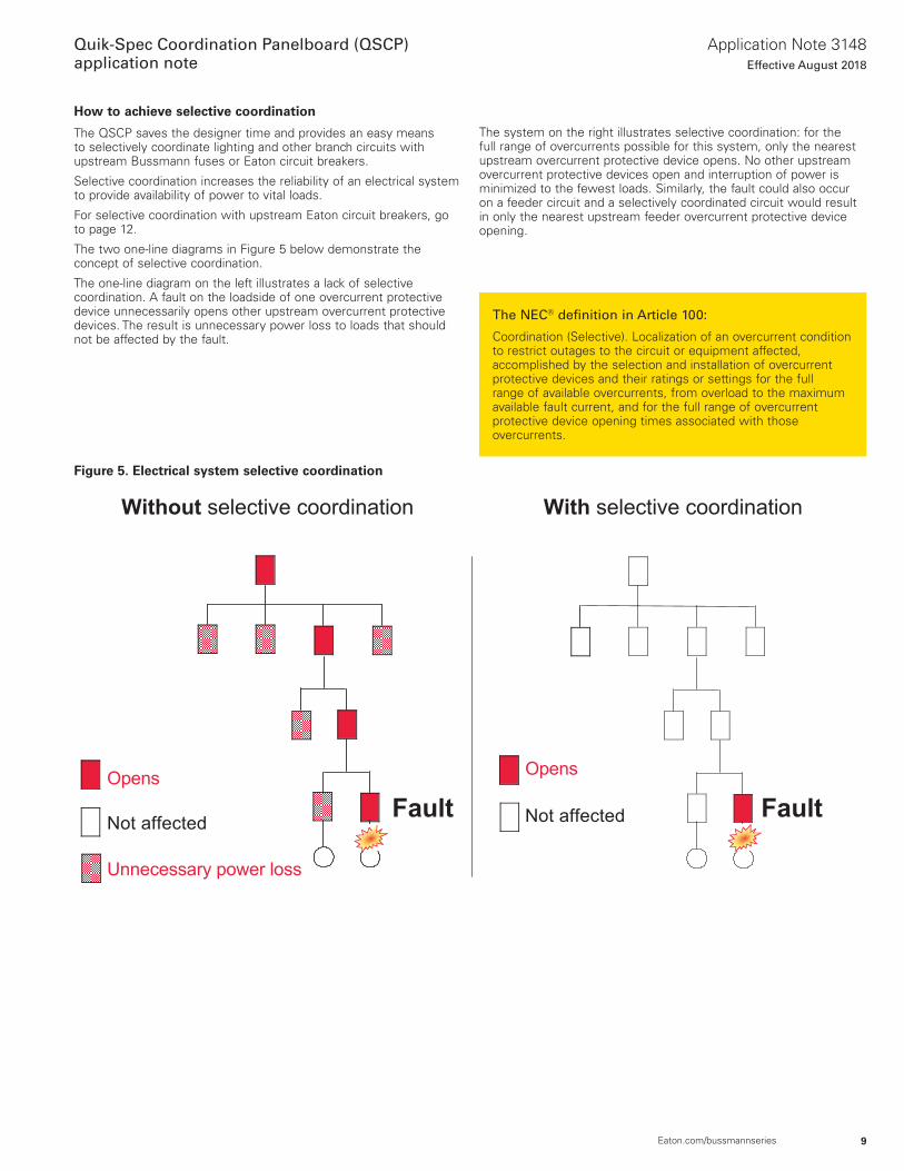
The two one-line diagrams in Figure 5 below demonstrate the concept of selective coordination .
The one-line diagram on the left illustrates a lack of selective coordination . A fault on the loadside of one overcurrent protective device unnecessarily opens other upstream overcurrent protective devices . The result is unnecessary power loss to loads that should not be affected by the fault .
Figure 5. Electrical system selective coordination
Without selective coordination
Opens
Not affected
Unnecessary power loss
Opens
Fault Not affected
With selective coordination
Fault
The NEC® definition in Article 100:
Coordination (Selective) . Localization of an overcurrent condition to restrict outages to the circuit or equipment affected, accomplished by the selection and installation of overcurrent protective devices and their ratings or settings for the full range of available overcurrents, from overload to the maximum available fault current, and for the full range of overcurrent protective device opening times associated with those overcurrents .
The system on the right illustrates selective coordination: for the full range of overcurrents possible for this system, only the nearest upstream overcurrent protective device opens . No other upstream overcurrent protective devices open and interruption of power is minimized to the fewest loads . Similarly, the fault could also occur on a feeder circuit and a selectively coordinated circuit would result in only the nearest upstream feeder overcurrent protective device opening .
10
Application Note 3148Effective August 2018
Quik-Spec Coordination Panelboard (QSCP)application note
Eaton.com/bussmannseries
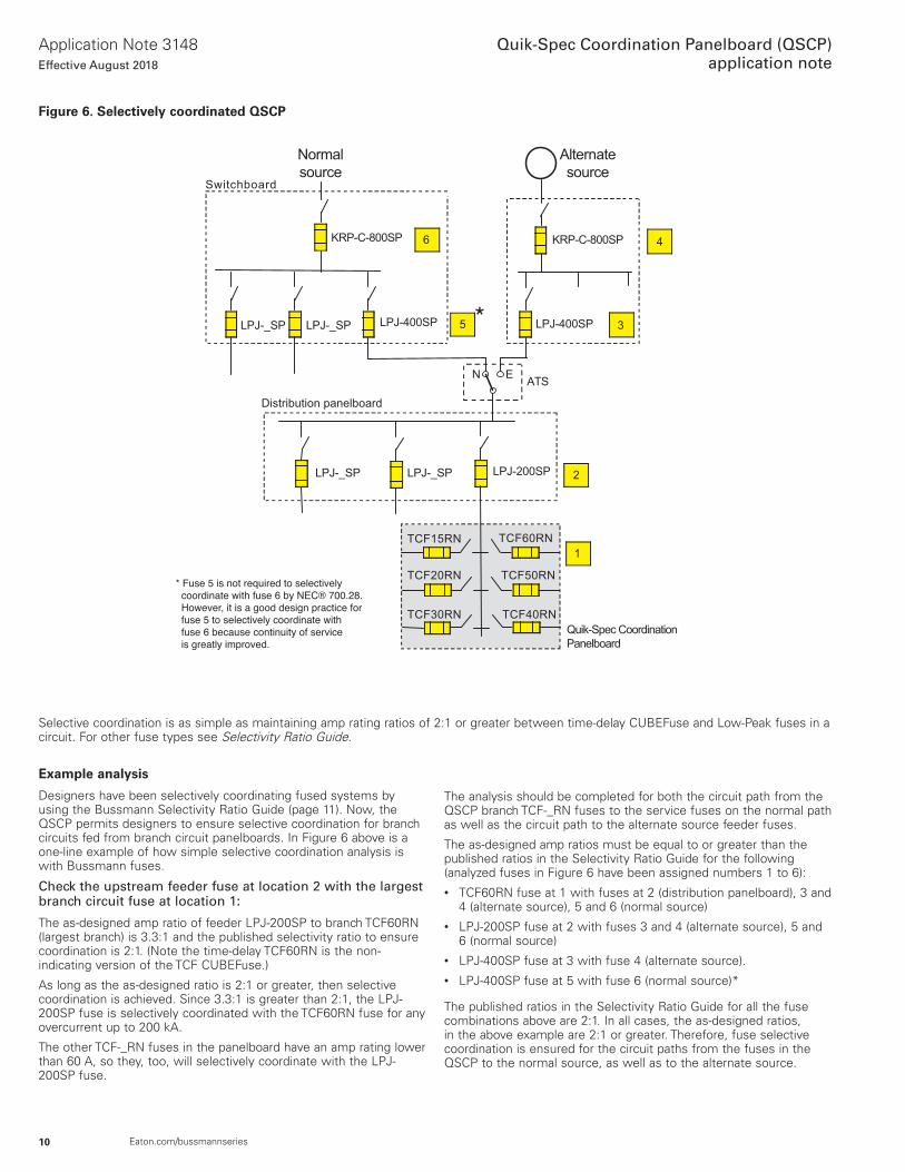
Figure 6. Selectively coordinated QSCP
Selective coordination is as simple as maintaining amp rating ratios of 2:1 or greater between time-delay CUBEFuse and Low-Peak fuses in a circuit . For other fuse types see Selectivity Ratio Guide .
ATS
Alternate
source
Normal
source
LPJ-400SP
KRP-C-800SP
Quik-Spec Coordination
Panelboard
LPJ-_SP
Switchboard
Distribution panelboard
1
2
3
4
5
6
TCF15RN
LPJ-_SP LPJ-400SP
KRP-C-800SP
LPJ-_SP LPJ-200SPLPJ-_SP
TCF40RN
TCF50RN
TCF60RN
TCF30RN
TCF20RN
N E
* Fuse 5 is not required to selectively coordinate with fuse 6 by NEC® 700.28. However, it is a good design practice for fuse 5 to selectively coordinate with fuse 6 because continuity of service is greatly improved.
*
Example analysis
Designers have been selectively coordinating fused systems by using the Bussmann Selectivity Ratio Guide (page 11) . Now, the QSCP permits designers to ensure selective coordination for branch circuits fed from branch circuit panelboards . In Figure 6 above is a one-line example of how simple selective coordination analysis is with Bussmann fuses .
Check the upstream feeder fuse at location 2 with the largest branch circuit fuse at location 1:
The as-designed amp ratio of feeder LPJ-200SP to branch TCF60RN (largest branch) is 3 .3:1 and the published selectivity ratio to ensure coordination is 2:1 . (Note the time-delay TCF60RN is the non-indicating version of the TCF CUBEFuse .)
As long as the as-designed ratio is 2:1 or greater, then selective coordination is achieved . Since 3 .3:1 is greater than 2:1, the LPJ-200SP fuse is selectively coordinated with the TCF60RN fuse for any overcurrent up to 200 kA .
The other TCF-_RN fuses in the panelboard have an amp rating lower than 60 A, so they, too, will selectively coordinate with the LPJ-200SP fuse .
The analysis should be completed for both the circuit path from the QSCP branch TCF-_RN fuses to the service fuses on the normal path as well as the circuit path to the alternate source feeder fuses .
The as-designed amp ratios must be equal to or greater than the published ratios in the Selectivity Ratio Guide for the following (analyzed fuses in Figure 6 have been assigned numbers 1 to 6):• TCF60RN fuse at 1 with fuses at 2 (distribution panelboard), 3 and
4 (alternate source), 5 and 6 (normal source)• LPJ-200SP fuse at 2 with fuses 3 and 4 (alternate source), 5 and
6 (normal source)• LPJ-400SP fuse at 3 with fuse 4 (alternate source) .• LPJ-400SP fuse at 5 with fuse 6 (normal source)*
The published ratios in the Selectivity Ratio Guide for all the fuse combinations above are 2:1 . In all cases, the as-designed ratios, in the above example are 2:1 or greater . Therefore, fuse selective coordination is ensured for the circuit paths from the fuses in the QSCP to the normal source, as well as to the alternate source .
11
Application Note 3148Effective August 2018
Quik-Spec Coordination Panelboard (QSCP)application note
Eaton.com/bussmannseries
Selective coordination using fuses
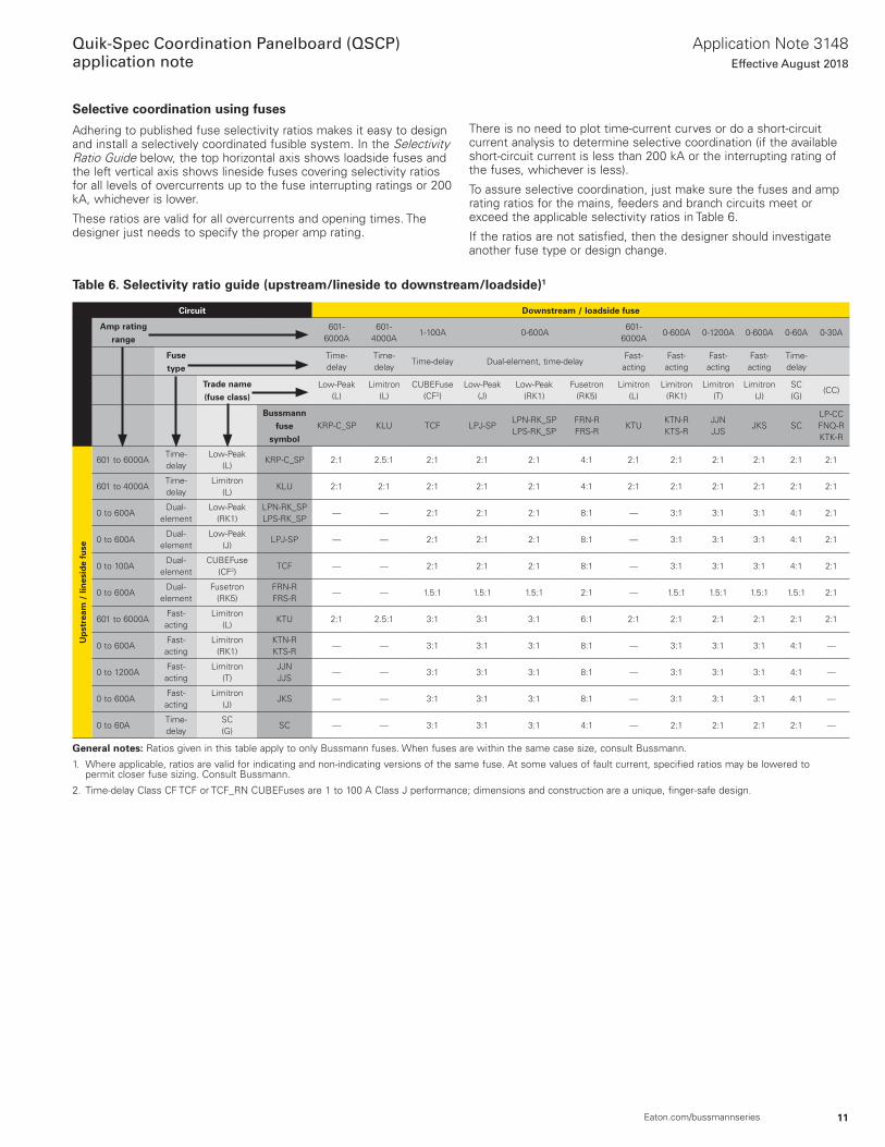
Adhering to published fuse selectivity ratios makes it easy to design and install a selectively coordinated fusible system . In the Selectivity Ratio Guide below, the top horizontal axis shows loadside fuses and the left vertical axis shows lineside fuses covering selectivity ratios for all levels of overcurrents up to the fuse interrupting ratings or 200 kA, whichever is lower .
These ratios are valid for all overcurrents and opening times . The designer just needs to specify the proper amp rating .
There is no need to plot time-current curves or do a short-circuit current analysis to determine selective coordination (if the available short-circuit current is less than 200 kA or the interrupting rating of the fuses, whichever is less) .
To assure selective coordination, just make sure the fuses and amp rating ratios for the mains, feeders and branch circuits meet or exceed the applicable selectivity ratios in Table 6 .
If the ratios are not satisfied, then the designer should investigate another fuse type or design change .
Table 6. Selectivity ratio guide (upstream/lineside to downstream/loadside)1
Circuit Downstream / loadside fuse
Amp rating range
601-6000A
601-4000A
1-100A 0-600A601-
6000A0-600A 0-1200A 0-600A 0-60A 0-30A
Fuse type
Time-delay
Time-delay
Time-delay Dual-element, time-delayFast-acting
Fast-acting
Fast-acting
Fast-acting
Time-delay
Trade name (fuse class)
Low-Peak (L)
Limitron (L)
CUBEFuse (CF2)
Low-Peak (J)
Low-Peak (RK1)
Fusetron (RK5)
Limitron (L)
Limitron (RK1)
Limitron (T)
Limitron (J)
SC (G)
(CC)
Bussmann fuse
symbol
KRP-C_SP KLU TCF LPJ-SPLPN-RK_SP LPS-RK_SP
FRN-R FRS-R
KTUKTN-R KTS-R
JJN JJS
JKS SCLP-CC FNQ-R KTK-R
Up
stre
am /
lin
esid
e fu
se
601 to 6000ATime-delay
Low-Peak (L)
KRP-C_SP 2:1 2 .5:1 2:1 2:1 2:1 4:1 2:1 2:1 2:1 2:1 2:1 2:1
601 to 4000ATime-delay
Limitron (L)
KLU 2:1 2:1 2:1 2:1 2:1 4:1 2:1 2:1 2:1 2:1 2:1 2:1
0 to 600ADual-
elementLow-Peak
(RK1)LPN-RK_SP LPS-RK_SP
— — 2:1 2:1 2:1 8:1 — 3:1 3:1 3:1 4:1 2:1
0 to 600ADual-
elementLow-Peak
(J)LPJ-SP — — 2:1 2:1 2:1 8:1 — 3:1 3:1 3:1 4:1 2:1
0 to 100ADual-
elementCUBEFuse
(CF2)TCF — — 2:1 2:1 2:1 8:1 — 3:1 3:1 3:1 4:1 2:1
0 to 600ADual-
elementFusetron
(RK5)FRN-R FRS-R
— — 1 .5:1 1 .5:1 1 .5:1 2:1 — 1 .5:1 1 .5:1 1 .5:1 1 .5:1 2:1
601 to 6000AFast-acting
Limitron (L)
KTU 2:1 2 .5:1 3:1 3:1 3:1 6:1 2:1 2:1 2:1 2:1 2:1 2:1
0 to 600AFast-acting
Limitron (RK1)
KTN-R KTS-R
— — 3:1 3:1 3:1 8:1 — 3:1 3:1 3:1 4:1 —
0 to 1200AFast-acting
Limitron (T)
JJN JJS
— — 3:1 3:1 3:1 8:1 — 3:1 3:1 3:1 4:1 —
0 to 600AFast-acting
Limitron (J)
JKS — — 3:1 3:1 3:1 8:1 — 3:1 3:1 3:1 4:1 —
0 to 60ATime-delay
SC (G)
SC — — 3:1 3:1 3:1 4:1 — 2:1 2:1 2:1 2:1 —
General notes: Ratios given in this table apply to only Bussmann fuses . When fuses are within the same case size, consult Bussmann .
1 . Where applicable, ratios are valid for indicating and non-indicating versions of the same fuse . At some values of fault current, specified ratios may be lowered to permit closer fuse sizing . Consult Bussmann .
2 . Time-delay Class CF TCF or TCF_RN CUBEFuses are 1 to 100 A Class J performance; dimensions and construction are a unique, finger-safe design .
12
Application Note 3148Effective August 2018
Quik-Spec Coordination Panelboard (QSCP)application note
Eaton.com/bussmannseries
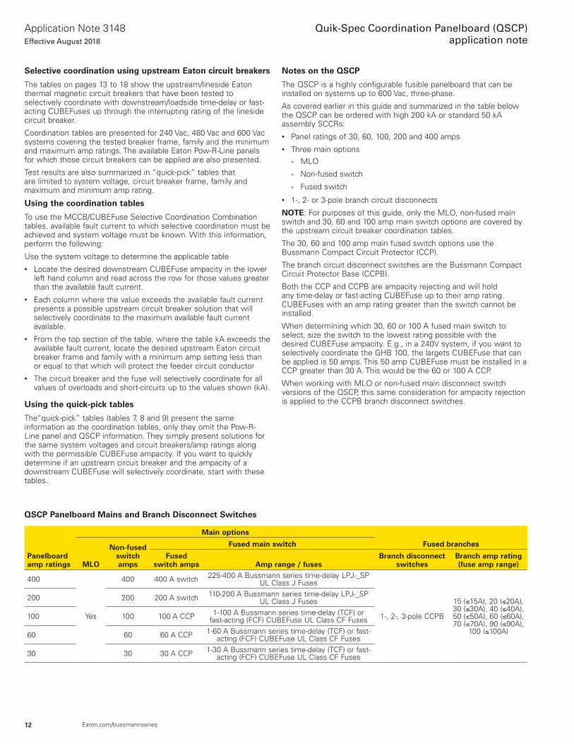
QSCP Panelboard Mains and Branch Disconnect Switches
Panelboard amp ratings
Main options
Fused branches
MLO
Non-fused switchamps
Fused main switch
Fused switch amps Amp range / fuses
Branch disconnect switches
Branch amp rating (fuse amp range)
400
Yes
400 400 A switch 225-400 A Bussmann series time-delay LPJ-_SP UL Class J Fuses
1-, 2-, 3-pole CCPB
15 (≤15A), 20 (≤20A), 30 (≤30A), 40 (≤40A), 50 (≤50A), 60 (≤60A), 70 (≤70A), 90 (≤90A),
100 (≤100A)
200 200 200 A switch 110-200 A Bussmann series time-delay LPJ-_SP UL Class J Fuses
100 100 100 A CCP 1-100 A Bussmann series time-delay (TCF) or fast-acting (FCF) CUBEFuse UL Class CF Fuses
60 60 60 A CCP 1-60 A Bussmann series time-delay (TCF) or fast-acting (FCF) CUBEFuse UL Class CF Fuses
30 30 30 A CCP 1-30 A Bussmann series time-delay (TCF) or fast-acting (FCF) CUBEFuse UL Class CF Fuses
Selective coordination using upstream Eaton circuit breakers
The tables on pages 13 to 18 show the upstream/lineside Eaton thermal magnetic circuit breakers that have been tested to selectively coordinate with downstream/loadside time-delay or fast-acting CUBEFuses up through the interrupting rating of the lineside circuit breaker .
Coordination tables are presented for 240 Vac, 480 Vac and 600 Vac systems covering the tested breaker frame, family and the minimum and maximum amp ratings . The available Eaton Pow-R-Line panels for which those circuit breakers can be applied are also presented .
Test results are also summarized in “quick-pick” tables that are limited to system voltage, circuit breaker frame, family and maximum and minimum amp rating .
Using the coordination tables
To use the MCCB/CUBEFuse Selective Coordination Combination tables, available fault current to which selective coordination must be achieved and system voltage must be known . With this information, perform the following:
Use the system voltage to determine the applicable table• Locate the desired downstream CUBEFuse ampacity in the lower
left hand column and read across the row for those values greater than the available fault current .
• Each column where the value exceeds the available fault current presents a possible upstream circuit breaker solution that will selectively coordinate to the maximum available fault current available .
• From the top section of the table, where the table kA exceeds the available fault current, locate the desired upstream Eaton circuit breaker frame and family with a minimum amp setting less than or equal to that which will protect the feeder circuit conductor
• The circuit breaker and the fuse will selectively coordinate for all values of overloads and short-circuits up to the values shown (kA) .
Using the quick-pick tables
The“quick-pick” tables (tables 7, 8 and 9) present the same information as the coordination tables, only they omit the Pow-R-Line panel and QSCP information . They simply present solutions for the same system voltages and circuit breakers/amp ratings along with the permissible CUBEFuse ampacity . If you want to quickly determine if an upstream circuit breaker and the ampacity of a downstream CUBEFuse will selectively coordinate, start with these tables .
Notes on the QSCP
The QSCP is a highly configurable fusible panelboard that can be installed on systems up to 600 Vac, three-phase .
As covered earlier in this guide and summarized in the table below the QSCP can be ordered with high 200 kA or standard 50 kA assembly SCCRs:• Panel ratings of 30, 60, 100, 200 and 400 amps• Three main options
• MLO
• Non-fused switch
• Fused switch
• 1-, 2- or 3-pole branch circuit disconnects
NOTE: For purposes of this guide, only the MLO, non-fused main switch and 30, 60 and 100 amp main switch options are covered by the upstream circuit breaker coordination tables .
The 30, 60 and 100 amp main fused switch options use the Bussmann Compact Circuit Protector (CCP) .
The branch circuit disconnect switches are the Bussmann Compact Circuit Protector Base (CCPB) .
Both the CCP and CCPB are ampacity rejecting and will hold any time-delay or fast-acting CUBEFuse up to their amp rating . CUBEFuses with an amp rating greater than the switch cannot be installed .
When determining which 30, 60 or 100 A fused main switch to select, size the switch to the lowest rating possible with the desired CUBEFuse ampacity . E .g ., in a 240V system, if you want to selectively coordinate the GHB 100, the largets CUBEFuse that can be applied is 50 amps . This 50 amp CUBEFuse must be installed in a CCP greater than 30 A . This would be the 60 or 100 A CCP .
When working with MLO or non-fused main disconnect switch versions of the QSCP, this same consideration for ampacity rejection is applied to the CCPB branch disconnect switches .
13
Application Note 3148Effective August 2018
Quik-Spec Coordination Panelboard (QSCP)application note
Eaton.com/bussmannseries
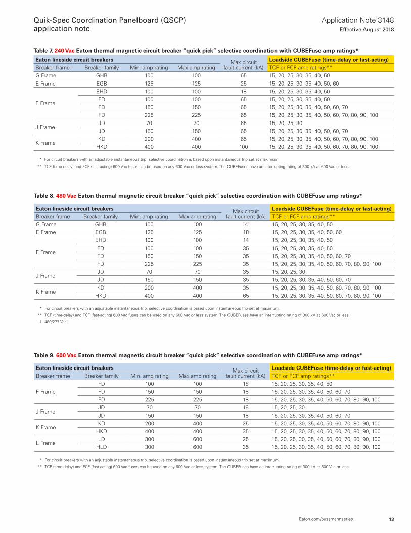
Table 7. 240 Vac Eaton thermal magnetic circuit breaker “quick pick” selective coordination with CUBEFuse amp ratings*
Eaton lineside circuit breakers Max circuit fault current (kA)
Loadside CUBEFuse (time-delay or fast-acting)Breaker frame Breaker family Min . amp rating Max amp rating TCF or FCF amp ratings**G Frame GHB 100 100 65 15, 20, 25, 30, 35, 40, 50E Frame EGB 125 125 25 15, 20, 25, 30, 35, 40, 50, 60
F Frame
EHD 100 100 18 15, 20, 25, 30, 35, 40, 50FD 100 100 65 15, 20, 25, 30, 35, 40, 50FD 150 150 65 15, 20, 25, 30, 35, 40, 50, 60, 70FD 225 225 65 15, 20, 25, 30, 35, 40, 50, 60, 70, 80, 90, 100
J FrameJD 70 70 65 15, 20, 25, 30JD 150 150 65 15, 20, 25, 30, 35, 40, 50, 60, 70
K FrameKD 200 400 65 15, 20, 25, 30, 35, 40, 50, 60, 70, 80, 90, 100
HKD 400 400 100 15, 20, 25, 30, 35, 40, 50, 60, 70, 80, 90, 100
* For circuit breakers with an adjustable instantaneous trip, selective coordination is based upon instantaneous trip set at maximum .
** TCF (time-delay) and FCF (fast-acting) 600 Vac fuses can be used on any 600 Vac or less system . The CUBEFuses have an interrupting rating of 300 kA at 600 Vac or less .
Table 8. 480 Vac Eaton thermal magnetic circuit breaker “quick pick” selective coordination with CUBEFuse amp ratings*
Eaton lineside circuit breakers Max circuit fault current (kA)
Loadside CUBEFuse (time-delay or fast-acting)Breaker frame Breaker family Min . amp rating Max amp rating TCF or FCF amp ratings**G Frame GHB 100 100 14† 15, 20, 25, 30, 35, 40, 50E Frame EGB 125 125 18 15, 20, 25, 30, 35, 40, 50, 60
F Frame
EHD 100 100 14 15, 20, 25, 30, 35, 40, 50FD 100 100 35 15, 20, 25, 30, 35, 40, 50FD 150 150 35 15, 20, 25, 30, 35, 40, 50, 60, 70FD 225 225 35 15, 20, 25, 30, 35, 40, 50, 60, 70, 80, 90, 100
J FrameJD 70 70 35 15, 20, 25, 30JD 150 150 35 15, 20, 25, 30, 35, 40, 50, 60, 70
K FrameKD 200 400 35 15, 20, 25, 30, 35, 40, 50, 60, 70, 80, 90, 100
HKD 400 400 65 15, 20, 25, 30, 35, 40, 50, 60, 70, 80, 90, 100
* For circuit breakers with an adjustable instantaneous trip, selective coordination is based upon instantaneous trip set at maximum .
** TCF (time-delay) and FCF (fast-acting) 600 Vac fuses can be used on any 600 Vac or less system . The CUBEFuses have an interrupting rating of 300 kA at 600 Vac or less .
† 480/277 Vac
Table 9. 600 Vac Eaton thermal magnetic circuit breaker “quick pick” selective coordination with CUBEFuse amp ratings*
Eaton lineside circuit breakers Max circuit fault current (kA)
Loadside CUBEFuse (time-delay or fast-acting)Breaker frame Breaker family Min . amp rating Max amp rating TCF or FCF amp ratings**
F FrameFD 100 100 18 15, 20, 25, 30, 35, 40, 50FD 150 150 18 15, 20, 25, 30, 35, 40, 50, 60, 70FD 225 225 18 15, 20, 25, 30, 35, 40, 50, 60, 70, 80, 90, 100
J FrameJD 70 70 18 15, 20, 25, 30JD 150 150 18 15, 20, 25, 30, 35, 40, 50, 60, 70
K FrameKD 200 400 25 15, 20, 25, 30, 35, 40, 50, 60, 70, 80, 90, 100
HKD 400 400 35 15, 20, 25, 30, 35, 40, 50, 60, 70, 80, 90, 100
L FrameLD 300 600 25 15, 20, 25, 30, 35, 40, 50, 60, 70, 80, 90, 100
HLD 300 600 35 15, 20, 25, 30, 35, 40, 50, 60, 70, 80, 90, 100
* For circuit breakers with an adjustable instantaneous trip, selective coordination is based upon instantaneous trip set at maximum .
** TCF (time-delay) and FCF (fast-acting) 600 Vac fuses can be used on any 600 Vac or less system . The CUBEFuses have an interrupting rating of 300 kA at 600 Vac or less .
14
Application Note 3148Effective August 2018
Quik-Spec Coordination Panelboard (QSCP)application note
Eaton.com/bussmannseries
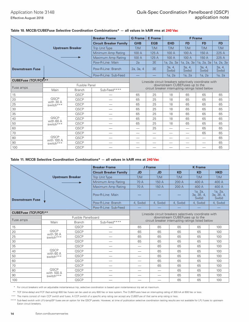
Table 11. MCCB Selective Coordination Combinations* — all values in kAIR rms at 240 Vac
Upstream Breaker
Breaker Frame J Frame K Frame
Circuit Breaker Family JD JD KD KD HKDTrip Unit Type T/M T/M T/M T/M T/MMinimum Amp Rating 70 A 150 A 200 A 400 A 400 AMaximum Amp Rating 70 A 150 A 200 A 400 A 400 A
Downstream FusePow-R-Line: Main — — —
1a, 2a, 3a, 3E, 4,
Swbd
1a, 2a, 3a, 3E, 4,
SwbdPow-R-Line: Branch 4, Swbd 4, Swbd 4, Swbd 4, Swbd 4, SwbdPow-R-Line: Sub-Feed — — — — —
CUBEFuse (TCF/FCF)** Lineside circuit breakers selectively coordinate with downstream CUBEFuses up to the
circuit breaker interrupting ratings listed belowFuse ampsFusible Panelboard
Main Branch Sub-Feed****15
QSCPwith 30 A switch***
QSCP — 65 65 65 65 10020 QSCP — 65 65 65 65 10025 QSCP — 65 65 65 65 10030 QSCP — 65 65 65 65 10035
QSCPwith 60 A switch***
QSCP — — 65 65 65 100
40 QSCP — — 65 65 65 10050 QSCP — — 65 65 65 10060 QSCP — — 65 65 65 10070
QSCPwith 100 A switch***
QSCP — — 65 65 65 10080 QSCP — — — 65 65 10090 QSCP — — — 65 65 100100 QSCP — — — 65 65 100
* For circuit breakers with an adjustable instantaneous trip, selective coordination is based upon instantaneous trip set at maximum .
** TCF (time-delay) and FCF (fast-acting) 600 Vac fuses can be used on any 600 Vac or less system . The CUBEFuses have an interrupting rating of 300 kA at 600 Vac or less .
*** The mains consist of main CCP switch and fuses . A CCP switch of a specific amp rating can accept any CUBEFuse of that same amp rating or less .
**** Sub-feed switch with LPJ-(amp)SP fuses are an option for the QSCP panels . However, at time of publication selective coordination testing results are not available for LPJ fuses to upstream Eaton circuit breakers .
Table 10. MCCB/CUBEFuse Selective Coordination Combinations* — all values in kAIR rms at 240 Vac
Upstream Breaker
Breaker Frame G Frame E Frame F Frame
Circuit Breaker Family GHB EGB EHD FD FD FDTrip Unit Type T/M T/M T/M T/M T/M T/MMinimum Amp Rating 100 A 125 A 100 A 100 A 150 A 225 AMaximum Amp Rating 100 A 125 A 100 A 100 A 150 A 225 A
Downstream Fuse
Pow-R-Line: Main 2a 3E 1a, 2a, 3a 1a, 2a, 3a 1a, 2a, 3a 1a, 2a, 3a
Pow-R-Line: Branch 2a, 3a, 4 3E 3a, 4, Swbd
3a, 4, Swbd
3a, 4, Swbd
3a, 4, Swbd
Pow-R-Line: Sub-Feed — — 1a, 2a 1a, 2a 1a, 2a 1a, 2a
CUBEFuse (TCF/FCF)** Lineside circuit breakers selectively coordinate with downstream CUBEFuses up to the
circuit breaker interrupting ratings listed belowFuse ampsFusible Panel
Main Branch Sub-Feed****15
QSCPwith 30 A switch***
QSCP — 65 25 18 65 65 6520 QSCP — 65 25 18 65 65 6525 QSCP — 65 25 18 65 65 6530 QSCP — 65 25 18 65 65 6535
QSCPwith 60 A switch***
QSCP — 65 25 18 65 65 6540 QSCP — 65 25 18 65 65 6550 QSCP — 65 25 18 65 65 6560 QSCP — — 25 — — 65 6570
QSCPwith 100 A switch***
QSCP — — — — — 65 6580 QSCP — — — — — — 6590 QSCP — — — — — — 65100 QSCP — — — — — — 65
15
Application Note 3148Effective August 2018
Quik-Spec Coordination Panelboard (QSCP)application note
Eaton.com/bussmannseries
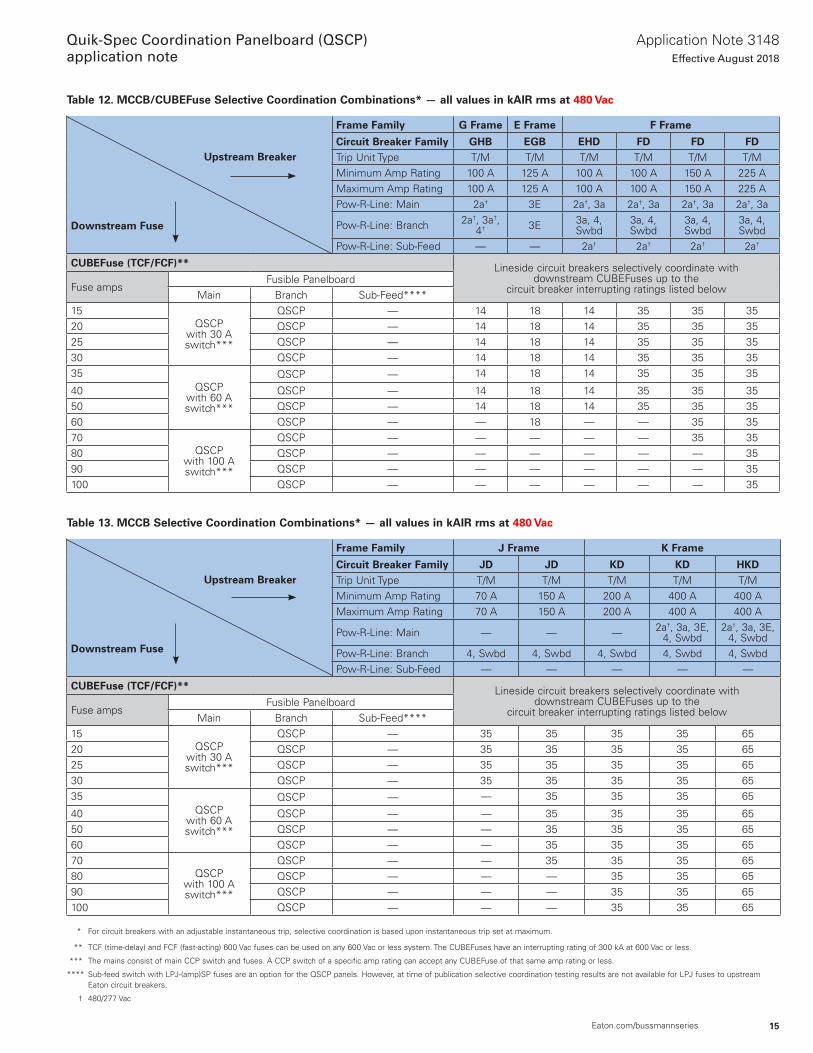
Table 12. MCCB/CUBEFuse Selective Coordination Combinations* — all values in kAIR rms at 480 Vac
Upstream Breaker
Frame Family G Frame E Frame F Frame
Circuit Breaker Family GHB EGB EHD FD FD FDTrip Unit Type T/M T/M T/M T/M T/M T/MMinimum Amp Rating 100 A 125 A 100 A 100 A 150 A 225 AMaximum Amp Rating 100 A 125 A 100 A 100 A 150 A 225 A
Downstream Fuse
Pow-R-Line: Main 2a† 3E 2a†, 3a 2a†, 3a 2a†, 3a 2a†, 3a
Pow-R-Line: Branch 2a†, 3a†, 4† 3E 3a, 4,
Swbd3a, 4, Swbd
3a, 4, Swbd
3a, 4, Swbd
Pow-R-Line: Sub-Feed — — 2a† 2a† 2a† 2a†
CUBEFuse (TCF/FCF)** Lineside circuit breakers selectively coordinate with downstream CUBEFuses up to the
circuit breaker interrupting ratings listed belowFuse ampsFusible Panelboard
Main Branch Sub-Feed****15
QSCPwith 30 A switch***
QSCP — 14 18 14 35 35 3520 QSCP — 14 18 14 35 35 3525 QSCP — 14 18 14 35 35 3530 QSCP — 14 18 14 35 35 3535
QSCPwith 60 A switch***
QSCP — 14 18 14 35 35 35
40 QSCP — 14 18 14 35 35 3550 QSCP — 14 18 14 35 35 3560 QSCP — — 18 — — 35 3570
QSCPwith 100 A switch***
QSCP — — — — — 35 3580 QSCP — — — — — — 3590 QSCP — — — — — — 35100 QSCP — — — — — — 35
Table 13. MCCB Selective Coordination Combinations* — all values in kAIR rms at 480 Vac
Upstream Breaker
Frame Family J Frame K Frame
Circuit Breaker Family JD JD KD KD HKDTrip Unit Type T/M T/M T/M T/M T/MMinimum Amp Rating 70 A 150 A 200 A 400 A 400 AMaximum Amp Rating 70 A 150 A 200 A 400 A 400 A
Downstream FusePow-R-Line: Main — — — 2a†, 3a, 3E,
4, Swbd2a†, 3a, 3E,
4, SwbdPow-R-Line: Branch 4, Swbd 4, Swbd 4, Swbd 4, Swbd 4, SwbdPow-R-Line: Sub-Feed — — — — —
CUBEFuse (TCF/FCF)** Lineside circuit breakers selectively coordinate with downstream CUBEFuses up to the
circuit breaker interrupting ratings listed belowFuse ampsFusible Panelboard
Main Branch Sub-Feed****15
QSCPwith 30 A switch***
QSCP — 35 35 35 35 6520 QSCP — 35 35 35 35 6525 QSCP — 35 35 35 35 6530 QSCP — 35 35 35 35 6535
QSCPwith 60 A switch***
QSCP — — 35 35 35 65
40 QSCP — — 35 35 35 6550 QSCP — — 35 35 35 6560 QSCP — — 35 35 35 6570
QSCPwith 100 A switch***
QSCP — — 35 35 35 6580 QSCP — — — 35 35 6590 QSCP — — — 35 35 65100 QSCP — — — 35 35 65
* For circuit breakers with an adjustable instantaneous trip, selective coordination is based upon instantaneous trip set at maximum .
** TCF (time-delay) and FCF (fast-acting) 600 Vac fuses can be used on any 600 Vac or less system . The CUBEFuses have an interrupting rating of 300 kA at 600 Vac or less .
*** The mains consist of main CCP switch and fuses . A CCP switch of a specific amp rating can accept any CUBEFuse of that same amp rating or less .
**** Sub-feed switch with LPJ-(amp)SP fuses are an option for the QSCP panels . However, at time of publication selective coordination testing results are not available for LPJ fuses to upstream Eaton circuit breakers .
† 480/277 Vac
16
Application Note 3148Effective August 2018
Quik-Spec Coordination Panelboard (QSCP)application note
Eaton.com/bussmannseries
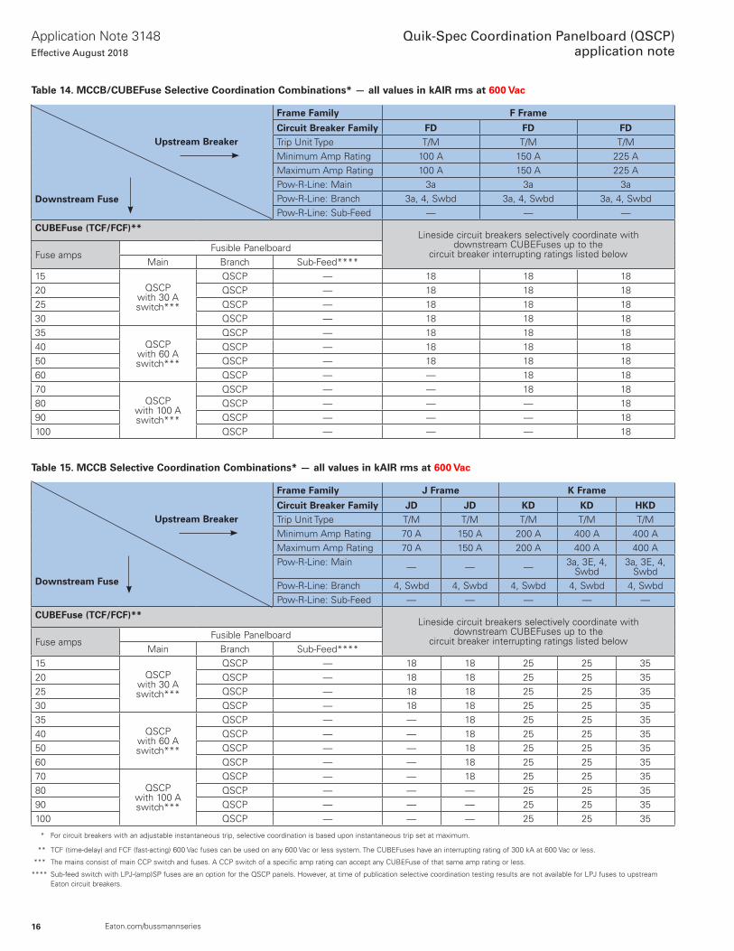
Table 14. MCCB/CUBEFuse Selective Coordination Combinations* — all values in kAIR rms at 600 Vac
Upstream Breaker
Frame Family F Frame
Circuit Breaker Family FD FD FDTrip Unit Type T/M T/M T/MMinimum Amp Rating 100 A 150 A 225 AMaximum Amp Rating 100 A 150 A 225 A
Downstream FusePow-R-Line: Main 3a 3a 3aPow-R-Line: Branch 3a, 4, Swbd 3a, 4, Swbd 3a, 4, SwbdPow-R-Line: Sub-Feed — — —
CUBEFuse (TCF/FCF)**Lineside circuit breakers selectively coordinate with
downstream CUBEFuses up to the circuit breaker interrupting ratings listed belowFuse amps
Fusible PanelboardMain Branch Sub-Feed****
15QSCP
with 30 A switch***
QSCP — 18 18 1820 QSCP — 18 18 1825 QSCP — 18 18 1830 QSCP — 18 18 1835
QSCPwith 60 A switch***
QSCP — 18 18 1840 QSCP — 18 18 1850 QSCP — 18 18 1860 QSCP — — 18 1870
QSCPwith 100 A switch***
QSCP — — 18 1880 QSCP — — — 1890 QSCP — — — 18100 QSCP — — — 18
Table 15. MCCB Selective Coordination Combinations* — all values in kAIR rms at 600 Vac
Upstream Breaker
Frame Family J Frame K Frame
Circuit Breaker Family JD JD KD KD HKDTrip Unit Type T/M T/M T/M T/M T/MMinimum Amp Rating 70 A 150 A 200 A 400 A 400 AMaximum Amp Rating 70 A 150 A 200 A 400 A 400 A
Downstream Fuse
Pow-R-Line: Main — — — 3a, 3E, 4, Swbd
3a, 3E, 4, Swbd
Pow-R-Line: Branch 4, Swbd 4, Swbd 4, Swbd 4, Swbd 4, SwbdPow-R-Line: Sub-Feed — — — — —
CUBEFuse (TCF/FCF)**Lineside circuit breakers selectively coordinate with
downstream CUBEFuses up to the circuit breaker interrupting ratings listed belowFuse amps
Fusible PanelboardMain Branch Sub-Feed****
15QSCP
with 30 A switch***
QSCP — 18 18 25 25 3520 QSCP — 18 18 25 25 3525 QSCP — 18 18 25 25 3530 QSCP — 18 18 25 25 3535
QSCPwith 60 A switch***
QSCP — — 18 25 25 3540 QSCP — — 18 25 25 3550 QSCP — — 18 25 25 3560 QSCP — — 18 25 25 3570
QSCPwith 100 A switch***
QSCP — — 18 25 25 3580 QSCP — — — 25 25 3590 QSCP — — — 25 25 35100 QSCP — — — 25 25 35
* For circuit breakers with an adjustable instantaneous trip, selective coordination is based upon instantaneous trip set at maximum .
** TCF (time-delay) and FCF (fast-acting) 600 Vac fuses can be used on any 600 Vac or less system . The CUBEFuses have an interrupting rating of 300 kA at 600 Vac or less .
*** The mains consist of main CCP switch and fuses . A CCP switch of a specific amp rating can accept any CUBEFuse of that same amp rating or less .
**** Sub-feed switch with LPJ-(amp)SP fuses are an option for the QSCP panels . However, at time of publication selective coordination testing results are not available for LPJ fuses to upstream Eaton circuit breakers .
17
Application Note 3148Effective August 2018
Quik-Spec Coordination Panelboard (QSCP)application note
Eaton.com/bussmannseries
Application and fuse sizing guidelines
CUBEFuse sizing guide
The time-delay CUBEFuses permit closer fuse sizing than non-time delay fuses for loads with inrush currents such as transformers or across the line AC motors . The CUBEFuse has excellent current-limiting characteristics (UL Class J) which results in superior short-circuit protection for circuit components and outstanding arc flash hazard mitigation when the arcing current is within the current-limiting range of the fuse . In addition, these fuses are rated 600 Vac and have a 300 kA interrupting rating .
Branch circuits, lighting and appliance loads (no motors)
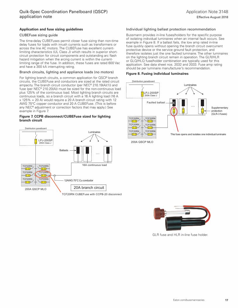
For lighting branch circuits, a common application for QSCP branch circuits, the CUBEFuse and conductors are sized at the rated circuit ampacity . The branch circuit conductor (per NEC® 210 .19(A)(1)) and fuse (per NEC® 210 .20(A)) must be sized for the non-continuous load plus 125% of the continuous load . Most lighting branch circuits are continuous loads, so a branch circuit with a 16 A lighting load (16 A x 125% = 20 A) would require a 20 A branch circuit rating with 12 AWG 75°C copper conductor and 20 A CUBEFuse . (This is before any NEC® adjustment or correction factors that may apply .) See example in Figure 7 .
Figure 7. CCPB disconnect/CUBEFuse sized for lighting branch circuit
Individual lighting ballast protection recommendation
Bussmann provides in-line fuses/holders for the specific purpose of isolating individual luminaires when an internal fault occurs . See example in Figure 8 . If a ballast fails, the low amp rated in-line fuse quickly opens without opening the branch circuit overcurrent protective device or the service ground fault protection, and therefore isolates just the one faulted luminaire . The other luminaires on the lighting branch circuit remain in operation . The GLR/HLR or GLQ/HLQ fuse/holder combination are typically used for this application . See data sheet nos . 2032 and 2033 . Fuse amp rating should be per luminaire manufacturer’s recommendation .
Figure 8. Fusing individual luminaires
GLR fuse and HLR in-line fuse holder .
LPJ-200SP200A Class J
200A QSCP MLO
Distribution panelboard
TCF20RN
12AWG 75°C Cu conductor
…Ballasts
16A continuous load
20A branch circuit
Luminaires
TCF20RN CUBEFuse with CCPB-20 disconnect
TCF20RN TCF20RN
TCF20RNTCF20RN
TCF20RN
…Faulted ballast X
Supplementary
protection
(GLR-3 fuses)
This fuse opens and isolates one individual luminaire
Distribution panelboard
200A QSCP MLO
Luminaires
LPJ-200SP200A Class J
TCF20RN
TCF20RN TCF20RN
TCF20RN
TCF20RNTCF20RN
18
Application Note 3148Effective August 2018
Quik-Spec Coordination Panelboard (QSCP)application note
Eaton.com/bussmannseries
Branch circuits: Individual motor circuits
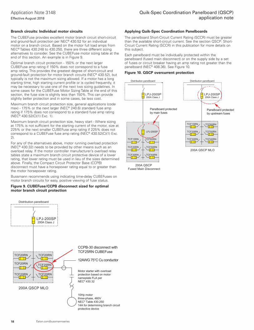
The CUBEFuse provides excellent motor branch circuit short-circuit and ground-fault protection per NEC® 430 .52 for an individual motor on a branch circuit . Based on the motor full load amps from NEC® Tables 430 .248 to 430 .250, there are three different sizing alternatives to consider . See the CUBEFuse motor sizing table at the end of this section . An example is in Figure 9 .
Optimal branch circuit protection - 150% or the next larger CUBEFuse amp rating if 150% does not correspond to a fuse amp rating . This provides the greatest degree of short-circuit and ground-fault protection for motor branch circuits (NEC® 430 .52), but typically is not the maximum sizing allowed . If a motor has a long starting time, high starting current profile or is cycled frequently, it may be necessary to use one of the next two sizing guidelines . In some cases for the CUBEFuse Motor Sizing Table at the end of this section, the fuse size is slightly less than 150% . This can provide slightly better protection and in some cases, be less cost .
Maximum branch circuit protection size, general applications (code max) - 175% or the next larger (NEC® 240 .6) standard fuse amp rating if 175% does not correspond to a standard fuse amp rating (NEC® 430 .52(C)(1) Exc . 1) .
Maximum branch circuit protection size, heavy start - Where sizing at 175% is not sufficient for the starting current of the motor, size at 225% or the next smaller CUBEFuse amp rating if 225% does not correspond to a CUBEFuse fuse amp rating (NEC® 430 .52(C)(1) Exc . 2) .
For any of the alternatives above, motor running overload protection (NEC® 430 .32) needs to be provided by other means such as an overload relay . If the motor controller manufacturer’s overload relay tables state a maximum branch circuit protective device of a lower rating, that lower rating must be used in lieu of the sizes determined above . Finally, the Compact Circuit Protector Base (CCPB) disconnect must have a horsepower rating equal to or greater than the motor horsepower rating .
Bussmann recommends using indicating time-delay CUBEFuses on motor branch circuits for easy, positive viewing of fuse status .
Figure 9. CUBEFuse/CCPB disconnect sized for optimal motor branch circuit protection
Applying Quik-Spec Coordination Panelboards
The panelboard Short-Circuit Current Rating (SCCR) must be greater than the available short-circuit current . See the section QSCP: Short-Circuit Current Rating (SCCR) in this publication for more details on this subject .
Each panelboard must be individually protected within the panelboard (fused main disconnect) or on the supply side by a set of fuses or circuit breaker having an amp rating not greater than the panelboard (NEC® 408 .36) . See Figure 10 .
Figure 10. QSCP overcurrent protection
Motor starter with overload
protection based on motor
nameplate FLA per
NEC® 430.32
10Hp motor
three-phase, 460V
NEC® Table 430.250
14A for determining branch circuit
protective device
CCPB-30 disconnect with
TCF25RN CUBEFuse
Distribution panelboard
LPJ-200SP200A Class J
200A QSCP MLO
TCF25RN
12AWG 75°C Cu conductor
TCF20RN TCF20RN
TCF20RN
TCF20RN
TCF20RN
LPJ-200SP
Panelboard protected
by main fuses
Distribution panelboard Distribution panelboard
200A QSCP MLO
200A QSCP
Fused Main Disconnect
LPJ-200SP200A Class J
LPJ-200SP200A Class J
TCF15RN
TCF20RN
TCF30RN
TCF60RN
TCF50RN
TCF40RN
TCF15RN
TCF20RN
TCF30RN
TCF60RN
TCF50RN
TCF40RN
Panelboard protected
by upstream fuses
19
Application Note 3148Effective August 2018
Quik-Spec Coordination Panelboard (QSCP)application note
Eaton.com/bussmannseries
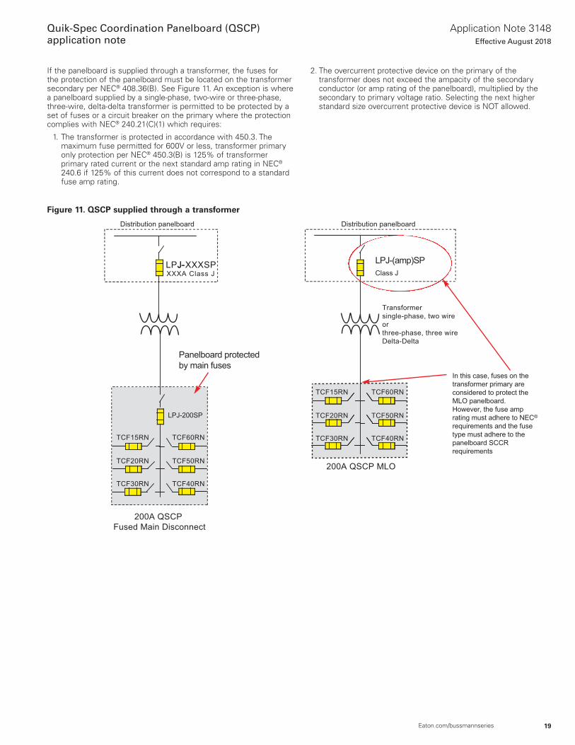
If the panelboard is supplied through a transformer, the fuses for the protection of the panelboard must be located on the transformer secondary per NEC® 408 .36(B) . See Figure 11 . An exception is where a panelboard supplied by a single-phase, two-wire or three-phase, three-wire, delta-delta transformer is permitted to be protected by a set of fuses or a circuit breaker on the primary where the protection complies with NEC® 240 .21(C)(1) which requires:
1 . The transformer is protected in accordance with 450 .3 . The maximum fuse permitted for 600V or less, transformer primary only protection per NEC® 450 .3(B) is 125% of transformer primary rated current or the next standard amp rating in NEC® 240 .6 if 125% of this current does not correspond to a standard fuse amp rating .
Figure 11. QSCP supplied through a transformer
2 . The overcurrent protective device on the primary of the transformer does not exceed the ampacity of the secondary conductor (or amp rating of the panelboard), multiplied by the secondary to primary voltage ratio . Selecting the next higher standard size overcurrent protective device is NOT allowed .
LPJ-XXXSPJ-XXXA Class J
LPJ-200SP
TCF15RN
Panelboard protected
by main fuses
LPJ-(amp)SP
Class J
Transformer
single-phase, two wire
or
three-phase, three wire
Delta-Delta
In this case, fuses on the
transformer primary are
considered to protect the
MLO panelboard.
However, the fuse amp
rating must adhere to NEC®
requirements and the fuse
type must adhere to the
panelboard SCCR
requirements
Distribution panelboardDistribution panelboard
TCF40RN
TCF50RN
TCF60RN
TCF30RN
TCF20RN
TCF15RN
TCF40RN
TCF50RN
TCF60RN
TCF30RN
TCF20RN
200A QSCP MLO
200A QSCP
Fused Main Disconnect
20
Application Note 3148Effective August 2018
Quik-Spec Coordination Panelboard (QSCP)application note
Eaton.com/bussmannseries
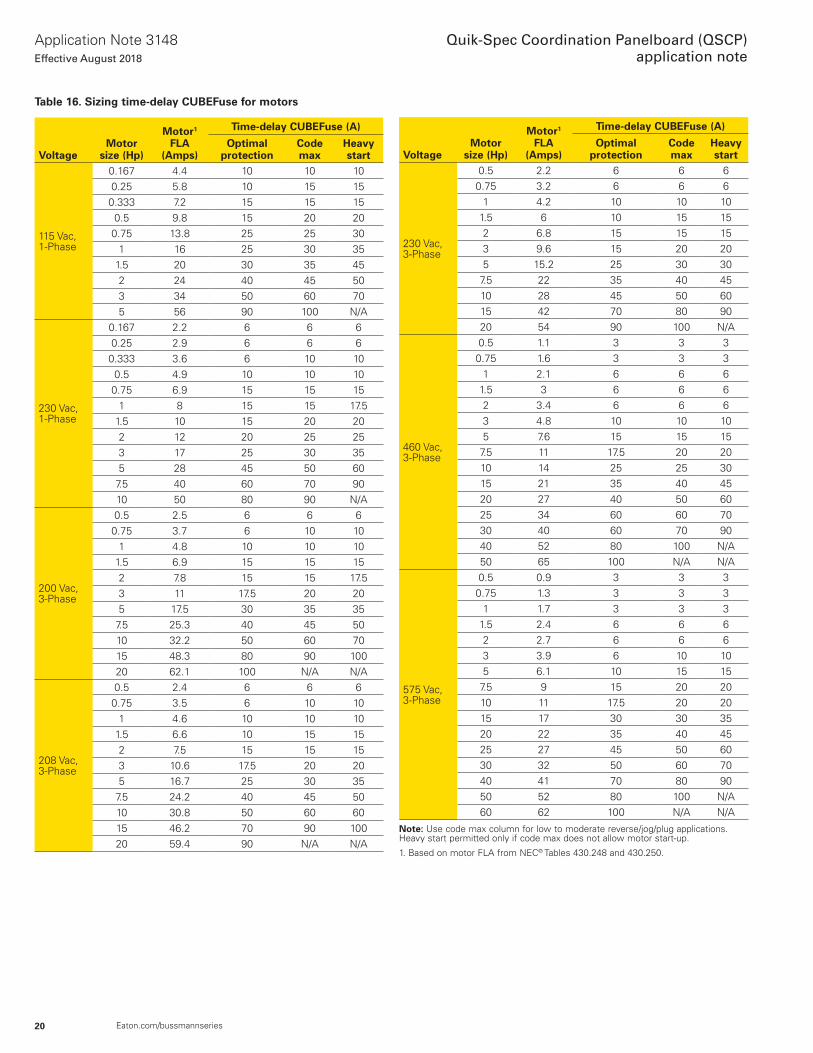
Table 16. Sizing time-delay CUBEFuse for motors
VoltageMotor
size (Hp)
Motor1 FLA
(Amps)
Time-delay CUBEFuse (A)
Optimal protection
Code max
Heavy start
115 Vac,1-Phase
0 .167 4 .4 10 10 100 .25 5 .8 10 15 150 .333 7 .2 15 15 150 .5 9 .8 15 20 200 .75 13 .8 25 25 30
1 16 25 30 351 .5 20 30 35 452 24 40 45 503 34 50 60 705 56 90 100 N/A
230 Vac,1-Phase
0 .167 2 .2 6 6 60 .25 2 .9 6 6 60 .333 3 .6 6 10 100 .5 4 .9 10 10 100 .75 6 .9 15 15 15
1 8 15 15 17 .51 .5 10 15 20 202 12 20 25 253 17 25 30 355 28 45 50 60
7 .5 40 60 70 9010 50 80 90 N/A
200 Vac,3-Phase
0 .5 2 .5 6 6 60 .75 3 .7 6 10 10
1 4 .8 10 10 101 .5 6 .9 15 15 152 7 .8 15 15 17 .53 11 17 .5 20 205 17 .5 30 35 35
7 .5 25 .3 40 45 5010 32 .2 50 60 7015 48 .3 80 90 10020 62 .1 100 N/A N/A
208 Vac,3-Phase
0 .5 2 .4 6 6 60 .75 3 .5 6 10 10
1 4 .6 10 10 101 .5 6 .6 10 15 152 7 .5 15 15 153 10 .6 17 .5 20 205 16 .7 25 30 35
7 .5 24 .2 40 45 5010 30 .8 50 60 6015 46 .2 70 90 10020 59 .4 90 N/A N/A
VoltageMotor
size (Hp)
Motor1 FLA
(Amps)
Time-delay CUBEFuse (A)
Optimal protection
Code max
Heavy start
230 Vac,3-Phase
0 .5 2 .2 6 6 60 .75 3 .2 6 6 6
1 4 .2 10 10 101 .5 6 10 15 152 6 .8 15 15 153 9 .6 15 20 205 15 .2 25 30 30
7 .5 22 35 40 4510 28 45 50 6015 42 70 80 9020 54 90 100 N/A
460 Vac,3-Phase
0 .5 1 .1 3 3 30 .75 1 .6 3 3 3
1 2 .1 6 6 61 .5 3 6 6 62 3 .4 6 6 63 4 .8 10 10 105 7 .6 15 15 15
7 .5 11 17 .5 20 2010 14 25 25 3015 21 35 40 4520 27 40 50 6025 34 60 60 7030 40 60 70 9040 52 80 100 N/A50 65 100 N/A N/A
575 Vac,3-Phase
0 .5 0 .9 3 3 30 .75 1 .3 3 3 3
1 1 .7 3 3 31 .5 2 .4 6 6 62 2 .7 6 6 63 3 .9 6 10 105 6 .1 10 15 15
7 .5 9 15 20 2010 11 17 .5 20 2015 17 30 30 3520 22 35 40 4525 27 45 50 6030 32 50 60 7040 41 70 80 9050 52 80 100 N/A60 62 100 N/A N/A
Note: Use code max column for low to moderate reverse/jog/plug applications . Heavy start permitted only if code max does not allow motor start-up .
1 . Based on motor FLA from NEC® Tables 430 .248 and 430 .250 .
21
Application Note 3148Effective August 2018
Quik-Spec Coordination Panelboard (QSCP)application note
Eaton.com/bussmannseries
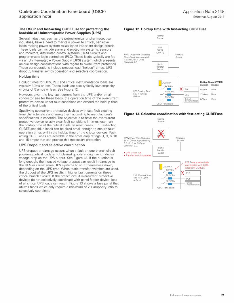
The QSCP and fast-acting CUBEFuse for protecting the loadside of Uninterruptable Power Supplies (UPS)
Several industries, such as the petrochemical or pharmaceutical industries, have a need to maintain power to critical, sensitive loads making power system reliability an important design criteria . These loads can include alarm and protection systems, sensors and monitors, distributed control systems (DCS) circuits and programmable logic controllers (PLC) . These loads typically are fed via an Uninterruptable Power Supply (UPS) system which presents unique design considerations with regard to overcurrent protection . These considerations include process load “holdup” times, UPS dropout, transfer switch operation and selective coordination .
Holdup time
Holdup times for DCS, PLC and critical instrumentation loads are typically 30ms or less . These loads are also typically low ampacity circuits of 5 amps or less . See Figure 12 .
However, given the low fault current from the UPS and/or small conductor size for these loads, the operation time of the overcurrent protective device under fault conditions can exceed the holdup time of the critical loads .
Specifying overcurrent protective devices with fast fault clearing time characteristics and sizing them according to manufacturer’s specifications is essential . The objective is to have the overcurrent protective device reliably clear fault conditions in times less than the holdup time of the critical loads . In most cases, FCF fast-acting CUBEFuses (blue label) can be sized small enough to ensure fault operation times within the holdup time of the critical devices . Fast-acting CUBEFuses are available in the small amp ratings (1, 3, 6, 10 and 15 amps) that can provide this necessary protection .
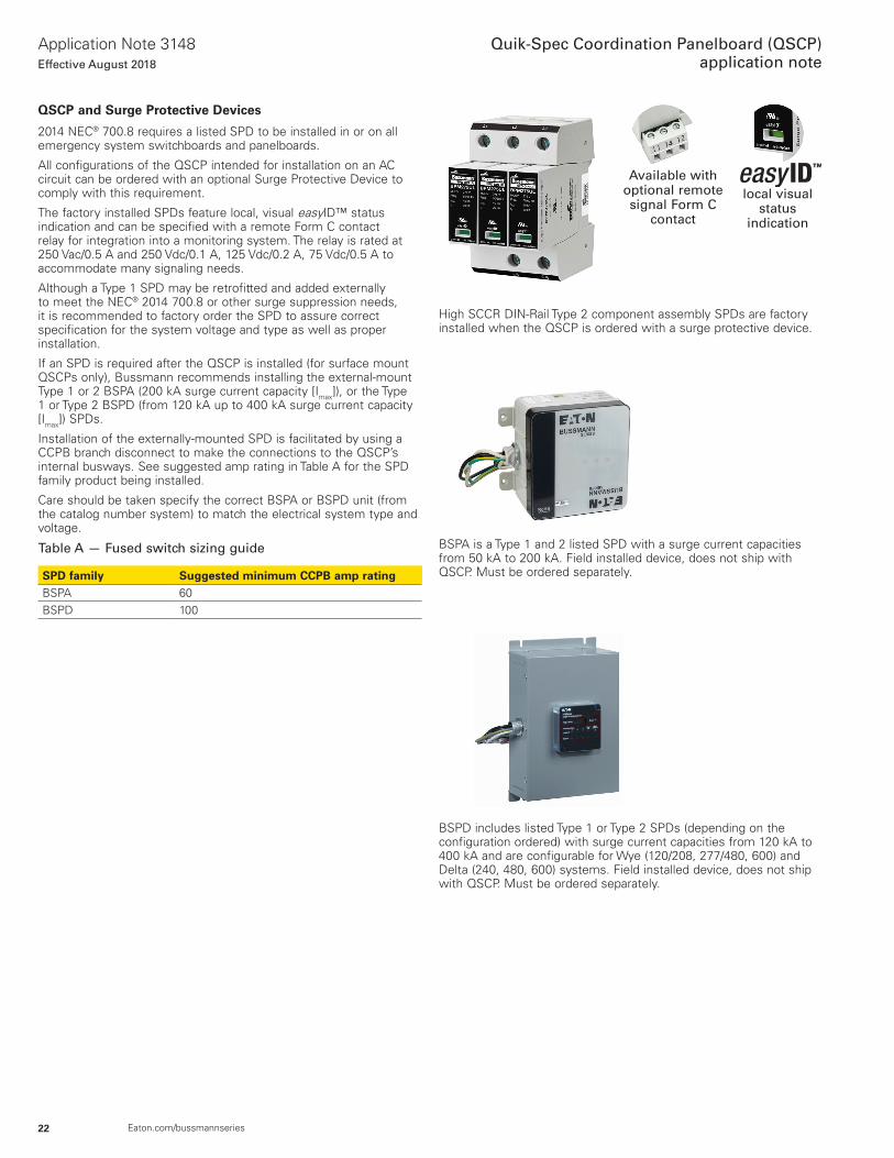
UPS Dropout and selective coordination
UPS dropout or damage occurs when a fault on one branch circuit powering critical loads is not cleared quickly enough so it induces voltage drop on the UPS output . See Figure 13 . If the duration is long enough, the induced voltage dropout can result in damage to the UPS or cause some UPS systems to shut themselves down, depending on the UPS type . When static transfer switches are used, the dropout of the UPS results in higher fault currents on these critical branch circuits . If the branch circuit overcurrent protective devices do not selectively coordinate with panel feeder device, loss of all critical UPS loads can result . Figure 13 shows a fuse panel that utilizes fuses which only require a minimum of 2:1 ampacity ratio to selectively coordinate .
Figure 12. Holdup time with fast-acting CUBEFuse
Figure 13. Selective coordination with fast-acting CUBEFuse
NormalSource
AlternateSource
PWM (Pulse Width Modulated)Short-Circuit Approximately1.5 x FLC for ¼ Cycle300-400A S.C.
FCF Clearing TimeSet. ¼-½ Cycle(4-8ms)
UPS30kVA
120V 1Ø
StaticTransferSwitch
QSCP Panelboard
FCF6RN
FCF10RN
FCF15RN
PLC
DCS
CriticalInstrumentation
Holdup Times 0 VRMSDuration Average
0-40ms 16ms
17-40ms 28ms
0-30ms 15ms
LPJ-200SP
NormalSource
AlternateSource
PWM (Pulse Width Modulated)Short-Circuit Approximately1.5 x FLC for ¼ Cycle300-400A S.C.
FCF Clearing TimeSet. ¼-½ Cycle(4-8ms)
UPS30kVA
120V 1Ø
StaticTransferSwitch
QSCP Panelboard
FCF6RN
FCF10RN
FCF15RN
PLC
DCS
CriticalInstrumentation
LPJ-200SP
• UPS Drops out• Transfer switch operates
FCF Fuse is selectivelycoordinated with 200Aupstream LPJ fuse
22
Application Note 3148Effective August 2018
Quik-Spec Coordination Panelboard (QSCP)application note
Eaton.com/bussmannseries
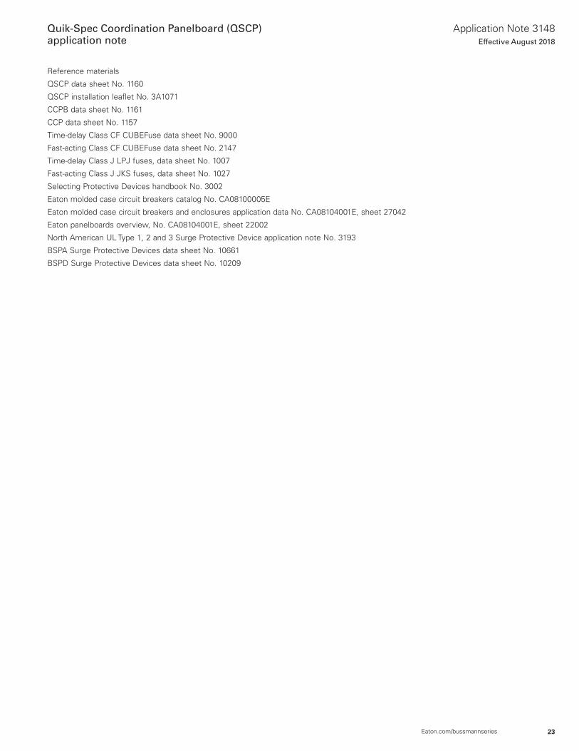
QSCP and Surge Protective Devices
2014 NEC® 700 .8 requires a listed SPD to be installed in or on all emergency system switchboards and panelboards .
All configurations of the QSCP intended for installation on an AC circuit can be ordered with an optional Surge Protective Device to comply with this requirement .
The factory installed SPDs feature local, visual easyID™ status indication and can be specified with a remote Form C contact relay for integration into a monitoring system . The relay is rated at 250 Vac/0 .5 A and 250 Vdc/0 .1 A, 125 Vdc/0 .2 A, 75 Vdc/0 .5 A to accommodate many signaling needs .
Although a Type 1 SPD may be retrofitted and added externally to meet the NEC® 2014 700 .8 or other surge suppression needs, it is recommended to factory order the SPD to assure correct specification for the system voltage and type as well as proper installation .
If an SPD is required after the QSCP is installed (for surface mount QSCPs only), Bussmann recommends installing the external-mount Type 1 or 2 BSPA (200 kA surge current capacity [Imax]), or the Type 1 or Type 2 BSPD (from 120 kA up to 400 kA surge current capacity [Imax]) SPDs .
Installation of the externally-mounted SPD is facilitated by using a CCPB branch disconnect to make the connections to the QSCP’s internal busways . See suggested amp rating in Table A for the SPD family product being installed .
Care should be taken specify the correct BSPA or BSPD unit (from the catalog number system) to match the electrical system type and voltage .
Table A — Fused switch sizing guide
SPD family Suggested minimum CCPB amp ratingBSPA 60BSPD 100
local visual status
indication
Available with optional remote signal Form C
contact
High SCCR DIN-Rail Type 2 component assembly SPDs are factory installed when the QSCP is ordered with a surge protective device .
BSPA is a Type 1 and 2 listed SPD with a surge current capacities from 50 kA to 200 kA . Field installed device, does not ship with QSCP . Must be ordered separately .
BSPD includes listed Type 1 or Type 2 SPDs (depending on the configuration ordered) with surge current capacities from 120 kA to 400 kA and are configurable for Wye (120/208, 277/480, 600) and Delta (240, 480, 600) systems . Field installed device, does not ship with QSCP . Must be ordered separately .
23
Application Note 3148Effective August 2018
Quik-Spec Coordination Panelboard (QSCP)application note
Eaton.com/bussmannseries
Reference materials
QSCP data sheet No . 1160
QSCP installation leaflet No . 3A1071
CCPB data sheet No . 1161
CCP data sheet No . 1157
Time-delay Class CF CUBEFuse data sheet No . 9000
Fast-acting Class CF CUBEFuse data sheet No . 2147
Time-delay Class J LPJ fuses, data sheet No . 1007
Fast-acting Class J JKS fuses, data sheet No . 1027
Selecting Protective Devices handbook No . 3002
Eaton molded case circuit breakers catalog No . CA08100005E
Eaton molded case circuit breakers and enclosures application data No . CA08104001E, sheet 27042
Eaton panelboards overview, No . CA08104001E, sheet 22002
North American UL Type 1, 2 and 3 Surge Protective Device application note No . 3193
BSPA Surge Protective Devices data sheet No . 10661
BSPD Surge Protective Devices data sheet No . 10209
Eaton1000 Eaton BoulevardCleveland, OH 44122United StatesEaton.com
Bussmann Division114 Old State RoadEllisville, MO 63021United StatesEaton.com/bussmannseries
© 2018 EatonAll Rights ReservedPrinted in USAPublication No. 3148 BU-SB14696August 2018
Eaton is a registered trademark.
All other trademarks are property of their respective owners.
Quik-Spec Coordination Panelboard (QSCP)application note
Application Note 3148Effective August 2018