Effect of Tooth Profile Modification In Asymmetric … 28/8-19-E.pdf8 Effect of Tooth Profile...
12
8 Effect of Tooth Profile Modification In Asymmetric Spur Gear Tooth on vibration Analysis with FEM Wasan ibraheem mansoor Misan University/college of Edecation/math Dep. Abstract :- The current research presents a theoretical study for the effect of the form of the edge side or what is known as (profile) of spur gear on the response of vibration .in order to achieve this goal,a study is mad for two different models first model (I) with (straight edge) and second (II) (curved profile)for model was constructed for each of the three-dimensional models using the application of ANSYS v11.0, and element (solid 45). The finite element method( FEM) was used to analyze the theoretical part with the same amount of load had been applied at the same locations (nodes) for both models. The results shown an increase in the values of the first five responses of the first model than in the second model and therefore less vibration and noise in the second model. The use of technology specific elements gives high-quality results for the adoption of best designs, reducing and reduces the time and effort and economic costs of these minute parts in machines and structures. يلمهماز على تحل النوع ال ترس مني السنر تعديل شكل منحن تأثيدةصر المحدلعناستخدام طريقة از باهتزا ا منصور.وسن إبراهيم من / كلية ا جامعة ميسااضياتة/ قسم الريساسي لتربية اصة: الخ- با يعارباو مانبية الجافة السن اة عن تأثير شكل حااسة نظريلحالي در يقدم البحث اprofile لتار) ستقيم النوع الم منspur gear ولتحقياولىحو اماة اللترددياوار اوامن از ضاهتزابة استجا على ا) جينسااة نمااوم درالفاادب تااا ا هاا و النمااوين اااتلابين مان لساان بجااI مسااتوناام بجا) straight profile لثاني وا) II منحناينام بجا) carved profile جينلنماو اد لكاابعاي اثا ث نماوان تام بنا) دام تطبي باستANSYS v11.0 ح وبعنصرsolid 45 دلمحادر االعناة ا وريقادمسات . ا) FEM ايلضان وتحلحت النتارت ا. هرفا)لعقادا قا المواد ناوحمل عنو مقدار الحوتم تسليط نام النظر لجانازهتز قيم الثاني وبالتالي ا في النمو عنفاو النموولى لرددات امو تل لستجابة قيم اد في تزاياعطاي نتا يدر المحدلعنادام تقنية اي اقل . ان استلثان ا في النمووضان والضادعتما لجاودة اليا عا
Transcript of Effect of Tooth Profile Modification In Asymmetric … 28/8-19-E.pdf8 Effect of Tooth Profile...

8
Effect of Tooth Profile Modification In Asymmetric Spur Gear Tooth on
vibration Analysis with FEM
Wasan ibraheem mansoor
Misan University/college of Edecation/math Dep.
Abstract :-
The current research presents a theoretical study for the effect of the form of
the edge side or what is known as (profile) of spur gear on the response of
vibration .in order to achieve this goal,a study is mad for two different models
first model (I) with (straight edge) and second (II) (curved profile)for model was
constructed for each of the three-dimensional models using the application of
ANSYS v11.0, and element (solid 45). The finite element method( FEM) was
used to analyze the theoretical part with the same amount of load had been
applied at the same locations (nodes) for both models. The results shown an
increase in the values of the first five responses of the first model than in the
second model and therefore less vibration and noise in the second model. The use
of technology specific elements gives high-quality results for the adoption of best
designs, reducing and reduces the time and effort and economic costs of these
minute parts in machines and structures.
تأثير تعديل شكل منحني السن ترس من النوع المهماز على تحليل
االهتزاز باستخدام طريقة العناصر المحددة
م.وسن إبراهيم منصور
لتربية األساسية/ قسم الرياضياتجامعة ميسان / كلية ا
-الخالصة:
( لتار profileيقدم البحث الحالي دراسة نظرية عن تأثير شكل حافة السن الجانبية او ماا يعارب با
( على استجابة االهتزاز ضامن األواوار الترددياة ال ماو األولىحولتحقيا spur gearمن النوع المستقيم
straight( بجاناام مسااتو Iلساان بجااانبين م تلاااين النمااو األو هاا ا الفاادب تاام دراسااة نمااو جين
profile والثاني )II بجانام منحناي )carved profile تام بناان نماو ث ثاي األبعااد لكا النماو جين )
FEM( . اسات دم وريقاة العنا ار المحادد solid 45ح وبعنصر ANSYS v11.0باست دام تطبي
لجانم النظر حوتم تسليط ناو مقدار الحمل عند ناو المواقا العقاد(. هرفارت النتاا الحتضان وتحليل ا
تزايد في قيم االستجابة لل مو ترددات األولى للنمو األو عنفا في النمو الثاني وبالتالي قيم االهتزاز
عالياة الجاود العتمااد والضوضان في النمو الثاني اقل . ان است دام تقنية العنا ر المحدد يعطاي نتاا

9
التصاميم األفضل مما ي تصر ويقلل في الجفد والوق والكلف االقتصادية لف ه األجزان الدقيقة فاي المكاا ن
والتراكيم .
1-1 Introduction :-
A Gear is a rotating machine part having cut teeth, or cogs , which mesh with
another toothed part in order to transmit torque . Two or more gears working in
tandem are called a transmission and can produce a mechanical advantage
through a gear ratio and thus may be considered a simple machine(1)
.
1.1.1 Spur gears:- which known also as straight - cut gears are one of
type of gear. They consist of a cylinder or disk and with the teeth projecting
radially as shown in fig (1-1)(2)
, and although they are not in form, thus the edge
of each tooth is straight and aligned parallel to the axis of rotation . These gears
can be meshed. Together correctly only if the ate fitted to parallel axis(3),(4),(5),(6)
.
1 Gears, Wikipedia, the free encyclopedia,7/9/2010, pag(1),http//en.Wikipedia.org/Wiki/Gear.
2 Gears, Wikipedia, the free encyclopedia,same refrence.
3 R.S.Khurmi & J.K.Gupta;'Theory of Machines',S.chand TECHNICAL,PUBLISHING,First
Multicolour Revised &updated edition ,2010,cha.12 ,pag(384).
4 R.S.Khurmi & J.K.Gupta; 'A Text book of Machine Design', S.chand ,RAMNAGAR, New Delhi-110
055,2010,chap.28,pag.(1203).
5 Joseph Edward Shigly & John Joseph Ulcker,JR;'Theory of Machines and Mechanisms', 2
nd
edition,McGraw-Hill,Inc,1995,chap.6, pag.(250-251)
6Budynas-Nisbett:Shigley
,s; "Mechanical Engineering Design", McGraw-Hill companies,2008 8
th
edition, chap.13,pag.(653-666).
Fig. (1-1) Spure gear and the terms used
with(1)
10
1.1.2 Vibration:-is one of the pre-dominate factors for the failures in rotating
machineries, especially, in the spur gear power transmission system ,for a heavy
load transmission, vibration is one of the important parameter to be maintained
within the limit of control ,a vibration in spur gear happens due to several reasons
such as errors (i.e,composite errors which includes static and dynamic
transmission error)(1)
. The prime source of vibration and noise in a gear system is
the transmission error between meshing gears. Transmission error is a term used
to describe or is defined as the differences between the theoretical and actual
positions between a pinion (driving gear) and a driven gear. It has been
recognized as a main source for mesh frequency excited noise and vibration. With
prior knowledge of the operating conditions of the gear set it is possible to design
the gears such that the vibration and noise is minimized(2)
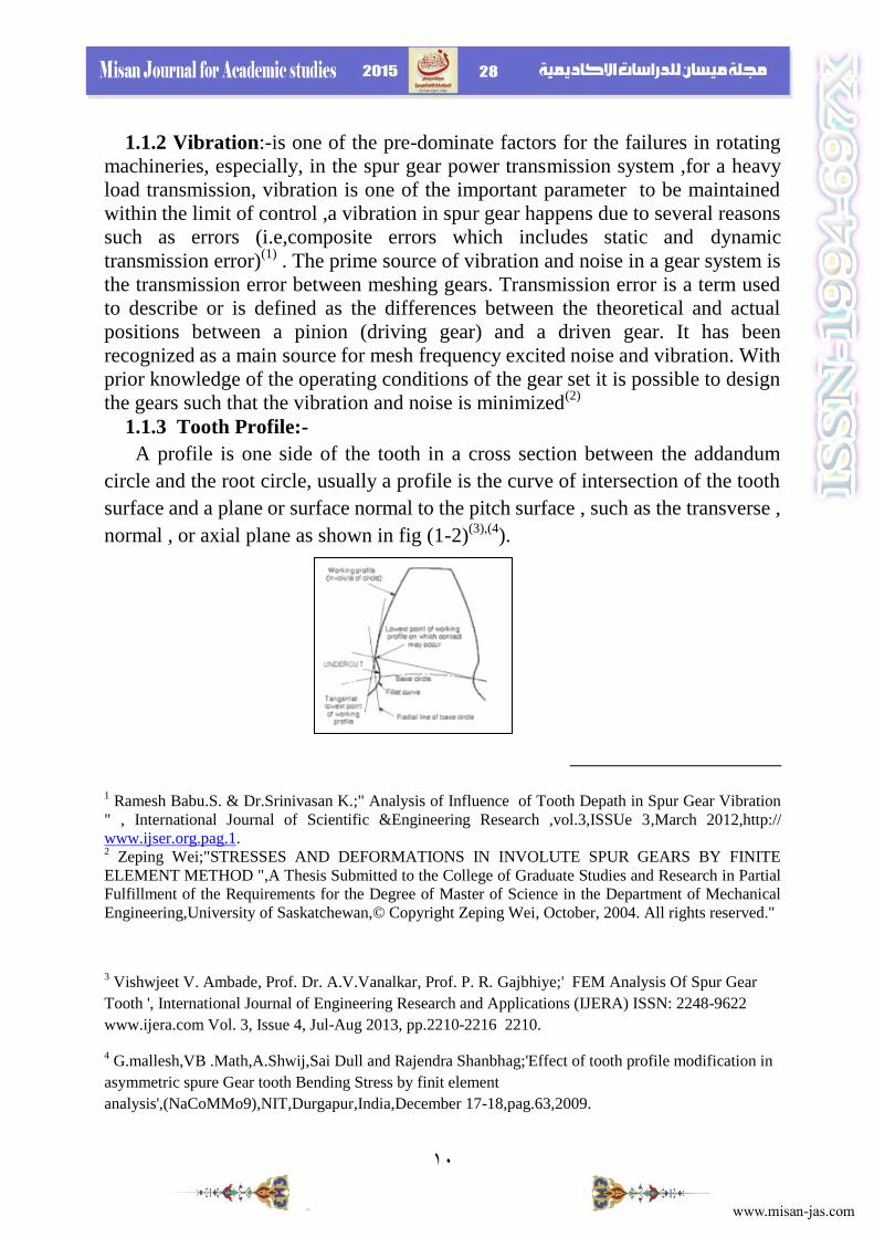
1.1.3 Tooth Profile:-
A profile is one side of the tooth in a cross section between the addandum
circle and the root circle, usually a profile is the curve of intersection of the tooth
surface and a plane or surface normal to the pitch surface , such as the transverse ,
normal , or axial plane as shown in fig (1-2)(3),(4
).
1 Ramesh Babu.S. & Dr.Srinivasan K.;" Analysis of Influence of Tooth Depath in Spur Gear Vibration
" , International Journal of Scientific &Engineering Research ,vol.3,ISSUe 3,March 2012,http://
www.ijser.org.pag.1. 2 Zeping Wei;"STRESSES AND DEFORMATIONS IN INVOLUTE SPUR GEARS BY FINITE
ELEMENT METHOD ",A Thesis Submitted to the College of Graduate Studies and Research in Partial
Fulfillment of the Requirements for the Degree of Master of Science in the Department of Mechanical
Engineering,University of Saskatchewan,© Copyright Zeping Wei, October, 2004. All rights reserved."
3 Vishwjeet V. Ambade, Prof. Dr. A.V.Vanalkar, Prof. P. R. Gajbhiye;' FEM Analysis Of Spur Gear
Tooth ', International Journal of Engineering Research and Applications (IJERA) ISSN: 2248-9622
www.ijera.com Vol. 3, Issue 4, Jul-Aug 2013, pp.2210-2216 2210.
4 G.mallesh,VB .Math,A.Shwij,Sai Dull and Rajendra Shanbhag;'Effect of tooth profile modification in
asymmetric spure Gear tooth Bending Stress by finit element
analysis',(NaCoMMo9),NIT,Durgapur,India,December 17-18,pag.63,2009.

11
Fig (1-2) the tooth profile(9),(10)
So ,in actual practice there are two type of teeth commonly used:-
1) Cycloidal teeth.
2) Inveloute teeth .
The standard gear profile in an involute that keeps the meshing gears in contact
as the gear teeth are revolved(1)
.In this paper the concerned with Involute one
which is a plane curve generated by a point on a tangent and had been compared
with another one which had sort of straight profile ,which rolls on the circle
without slipping or by a point on the taut string which in unwrapped from a
reed(2)
.
Using the present method ANSYS can solve three-dimensional and an
asymmetric model were built. First, parameter definitions were given and then
many points of the involute profile of gear were calculated to plot an involute
profile using a cylindrical system. The equations of an involute curve below were
taken from Zeping(3)
.
= radius of the base circle Where r=radius to the involute form ,
=vertorial angle at the pitch circle
= vertorial angle at the top of the tooth
𝜙=pressure angle at the pitch circle
One spur tooth profile was created using equation (1-1) of the first type (I) , as
are the outside diameter circle, the dedendum circle, and base circle of the gear.
Second, in ANSYS from the toolbars using “CREATE”, “COPY”, “MOVE”, and
1 R.S.Khurmi & J.K.Gupta;,pag(387).aformer refrence.
2 Dr. A. Tolga Bozdana Assistant Professor ;" ME 114 – Engineering Drawing II",Mechanical
Engineering University of Gaziantep, pag.
3 Zeping Wei.,same refrence.
12
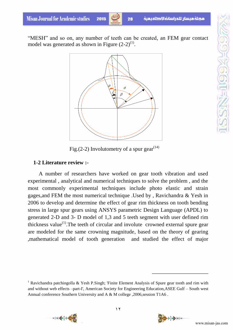
“MESH” and so on, any number of teeth can be created, an FEM gear contact
model was generated as shown in Figure (2-2)(1)
.
1-2 Literature review :-
A number of researchers have worked on gear tooth vibration and used
experimental , analytical and numerical techniques to solve the problem , and the
most commonly experimental techniques include photo elastic and strain
gages,and FEM the most numerical technique .Used by , Ravichandra & Yesh in
2006 to develop and determine the effect of gear rim thickness on tooth bending
stress in large spur gears using ANSYS parametric Design Language (APDL) to
generated 2-D and 3- D model of 1,3 and 5 teeth segment with user defined rim
thickness value(1)
.The teeth of circular and involute crowned external spure gear
are modeled for the same crowning magnitude, based on the theory of gearing
,mathematical model of tooth generation and studied the effect of major
1 Ravichandra patchingolla & Yesh P.Singh; 'Finite Element Analysis of Spure gear tooth and rim with
and without web effects –part-I', American Society for Engineering Education,ASEE Gulf – South west
Annual conference Southern University and A & M college ,2006,session T1A6 .
Fig.(2-2) Involutometry of a spur gear(14)

13
performance characteristics of uncrowned spur gear teeth using the FEM analyses
from Ansys were presented (1)
.
Natural frequencies and dynamic response of a spur gear sector were
investigated using 2-D FEM and the gear teeth were analyzed for different
operating speeds ,ANSYS software has been used on proposetred model to find
the natural frequencies by block Lanczos technique and displacements and
dynamic stresses by transient mode super position method (2)
. To estimate
transmission error in a gear system, the characteristics of involute spur gears were
analyzed using FEM , the contact stresses were examined by 2-D models in
ANSYS and results indicated that combined torsional mesh stiffness increases at
double pair of teeth and decreased in single pair teeth due to mesh cycle and the
change in torsional mesh stiffness leads to change in (Tr.) that causes noise and
vibration(3)
. Analysis of experimental data of gear rattle in Roots Blower Vacuum
Pumps reveals that the source of the noise and vibration problem is the backlash
nonlinearity due to gear teeth losing and re – establishing contact(4)
. FEM used to
developed the real model of the geared set using the self developed the software
and the vibration mode shapes show the relation to the moving center of masses
of the gear that carries the moving mass and show the vibration sensitivity of the
gear set to design parameters (5)
.A tooth depth is increased to identify the
reduction of vibration in a spur gear with two model descried and analyzed by
FEA software under harmonic analysis to identify the displacement and
acceleration of the gear tooth due tooth due to transmitted and radial load(6)
.
1 -Ramalingam Gurumani*, Subramaniam Shanmugam* ;'MODELING AND CONTACT ANALYSIS
OF CROWNED SPUR GEAR TEETH', Engineering MECHANICS, Vol. 18, 2011, No. 1, p. 65–78 .
2 ali H.Al-Wazir & Amal A.Abdulah; "NON-LINEAR ANALYSIS SPUR GEAR MESH BY FEM",
Journal of Kerbala University , vol.5,No.4,Scientific, December,2007.
3 Joanna Mason, Mart Homer & R.Eddie Wislon; "MATHEMATICAL MODELS OF GEAR RATTLE
IN ROOTS BLOWER VACUUM PUMPS", University of Bristol ,BS81TR.
4 Joanna Mason, Mart Homer & R.Eddie Wislon; "MATHEMATICAL MODELS OF GEAR RATTLE
IN ROOTS BLOWER VACUUM PUMPS", University of Bristol ,BS81TR.
5 Dejan Dimitrijević, Vera Nikolić-Stanojević;" Eigenfreuqency Analysis of the Spur Gear Pair with
Moving Excentric Masses on the Body of One of the Gears ", © Faculty of Mechanical Engineering,
Belgrade. All rights reserved FME Transactions (2007) 35, 157-163.
6Ramesh Babu.S* and Dr.Srinivasan.K; " Analysis of Influence of Tooth Depth in Spur Gear Vibration
", International Journal of Scientific & ineering Research, Volume 3, Issue 3, March-2012 1ISSN 2229-
5518.

14
2-1Finite Element Modeling :-
A program is developed using ANSYS parametric Design Language (APDL)
ver.11,to model the gear tooth involute profile of two type with different edge
shape as shown in figures shown to note the effect on vibration .The analysis is
preformed on 3-D finite element models in this paper the element is of the type
(solid 45) of solid structures and the element is defined by eight nodes having
three degrees of freedom at each node viz. Translation in the nodal X,Y and Z
direction. The material is assumed to be isotropic and homogeneous. The finite
element models are analyzed for the case of entire load acting at the HPSTC
(Highest Point of Single Tooth Contact). The edge length of the element along the
profile is calculated and the load is applied as a pressure on the profile edge each
time the same value on same nod for both design (involute profile model I and
involute profile model II ) .
3.1 Case illustrations :-
Table (1) provides the design and operating parameters of the standard spure
gear considered for two shape of profile (circular & straight profile) (1)
Table (1)Design and operating parameters of the standard spure gear
Description The value
Material 40 Ni2Cr Mo28(En24)
high strength
Ultimate tensile strength,Mpa 1550
Yield strength , Mpa 1300
Modulus of elasticity , Mpa 2.07*105
Density , Kg/m3
7840
Pitch circle diameter ,mm 180
Root diameter ,mm 175
Outsid diameter ,mm 184
Base diameter ,mm 169.15
Number of teeth 90
Radius of curvature at pitch point , mm 30.782
1 Ramalingam Gurumani*, Subramaniam Shanmugam* ;'MODELING AND CONTACT ANALYSIS
OF CROWNED SPUR GEAR TEETH', Engineering MECHANICS, Vol. 18, 2011, No. 1, p. 65–78 .

15
Fillet radius , mm 0.3 modula
Top land thickness 0.4 modula
Face wideth ,mm 30
Addendum ,mm 1 modula
Dedendum ,mm 1.25 modula
Poisson's ratio 0.25
Pressure angle ,deg 20
Contact pressure , N/mm2
1238
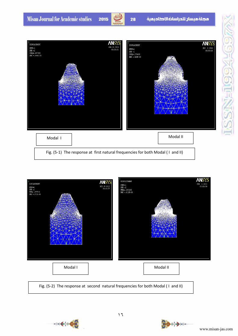
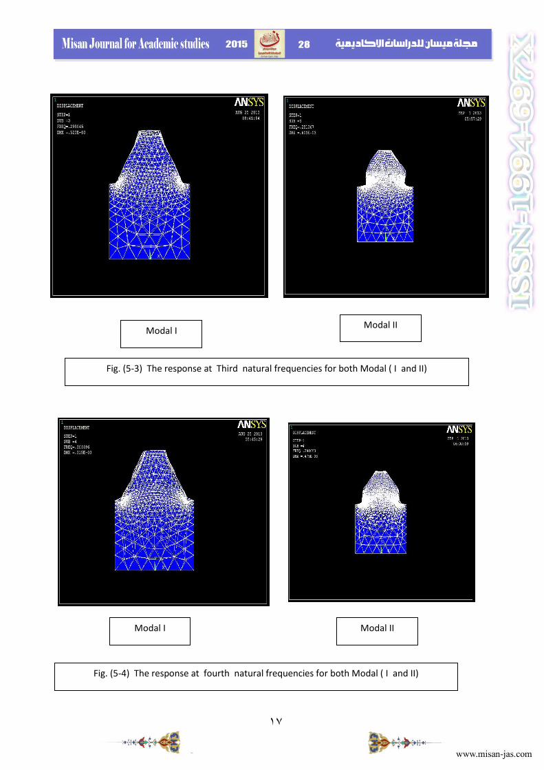
4.1 Results and Conclusions :-
4.1.1 results and figures :-
As mentioned above the results showed that when the involute gear profile of
straight edge had higher values at first five natural frequencies as in table (5-1)
compared with modal II(the modified one),the figures showed that modified
involute profile of modal II have lower vibration at the first five natural
frequencies as in (5-1),(5-2),(5-3)and (5-4) which shown the response of lower
value in modified modal (II) than modal( I) .
Table (5-1) the first five natural frequencies of two involute gear profile
types
Set Tim/ FREQ
Modal I (straight involute
gear profile)
Modal II (carved involute
gear profile)
1 0.29733 0.279425
2 0.29751 0.280485
3 0.29904 0.281367
4 0.30340 0.291083
5 0.30478 0.291555
16
Modal I Modal II
Fig. (5-1) The response at first natural frequencies for both Modal ( I and II)
Modal II Modal I
Fig. (5-2) The response at second natural frequencies for both Modal ( I and II)
17
Modal I Modal II
Fig. (5-3) The response at Third natural frequencies for both Modal ( I and II)
Modal II Modal I
Fig. (5-4) The response at fourth natural frequencies for both Modal ( I and II)

18
4-2 conclusions :-
As shown in tables (5-1) and (5-2) , and in figures above we notes that :-
1- The natural frequencies and vibration responses values had a relation with the
involute gear profile design ,that we had lower value for responses in modal(II)
the modified one with carved edge than modal(I) which had sort of straight edge .
2- The area of contact in modal (II) is slightly lower than that in modal (I) which
provide a less point of contact compared as a result lower vibration and noise.
3- It's evident from the result that vibration of spur gear can be modified by
modifying the involute gear profile design .
4- FEM is an acceptable method for study and analyzed and investigated the
effect of the involute gear profile design with vibration analysis .
5-1 Refrencess : 1- Ali H.Al-Wazir & Amal A.Abdulah; "NON-LINEAR ANALYSIS SPUR
GEAR MESH BY FEM", Journal of Kerbala University , vol.5,No.4,Scientific,
December,2007.
2- A.Tolga Bozdana Assistant Professor ;" ME 114 – Engineering Drawing
II",Mechanical Engineering University of Gaziantep
3-Budynas-Nisbett:Shigley,s;"MechanicalEngineeringDesign",McGraw-Hill
companies,8thedition,chap.13,pag.(653-666) ,2008.
4- Dejan Dimitrijević, Vera Nikolić-Stanojević;" Eigenfreuqency Analysis of
the Spur Gear Pair with Moving Excentric Masses on the Body of One of the
Fig. (5-5) The response at fifth natural frequencies for both Modal ( I and II)
Modal II Modal I
19
Gears ",©Faculty of Mechanical Engineering, Belgrade. All rights reserved FME
Transactions , 2007.
5- G.mallesh,VB .Math,A.Shwij,Sai Dull and Rajendra Shanbhag;'Effect of
tooth profile modification in asymmetric spure Gear tooth Bending Stress by finit
element analysis',(NaCoMMo9),NIT,Durgapur,India,December 17-18,2009.
6-Gears(1),http//en.,Wikipedia,thefreeencyclopedia,7/9/2010,
Wikipedia.org/Wiki/Gear.
7- Joanna Mason, Mart Homer & R.Eddie Wislon; "MATHEMATICAL
MODELS OF GEAR RATTLE IN ROOTS BLOWER VACUUM PUMPS",
University of Bristol ,BS81TR.vol.308, 4 December 2007.
8- Joseph Edward Shigly & John Joseph Ulcker,JR;'Theory of Machines and
Mechanisms', 2nd
edition,McGraw-Hill,Inc,chap.6,1995.
9- Ramalingam Gurumani*, Subramaniam Shanmugam* ;'MODELING AND
CONTACT ANALYSIS OF CROWNED SPUR GEAR TEETH', Engineering
MECHANICS, Vol. 18 , No. 1, 2011
10- Ramesh Babu.S. & Dr.Srinivasan K.;" Analysis of Influence of Tooth
Depath in Spur Gear Vibration " , International Journal of Scientific
&Engineering Research ,vol.3,ISSUe 3,http:// www.ijser.org.pag.1,March 2012.
11-
R.S.Khurmi&J.K.Gupta;'TheoryofMachines',S.chandTECHNICAL,PUBLISHIN
G,
First Multicolour Revised &updated edition,chap.12 ,2010.
12- Vishwjeet V. Ambade, Prof. Dr. A.V.Vanalkar, Prof. P. R. Gajbhiye;'
FEM Analysis Of Spur Gear Tooth ', International Journal of Engineering
Research and Applications (IJERA) ISSN: 2248-9622 www.ijera.com Vol. 3,
Issue 4, Jul-Aug, 2013.
13- Zeping Wei;"STRESSES AND DEFORMATIONS IN INVOLUTE SPUR
GEARS BY FINITE ELEMENT METHOD ",A Thesis Submitted to the College
of Graduate Studies and Research in Partial Fulfillment of the Requirements for
the Degree of Master of Science in the Department of Mechanical
Engineering,University of Saskatchewan,© Copyright Zeping WeiAll rights
reserved, October, 2004.


![Comparison of two maxillary protraction protocols: tooth ... · veloping class III malocclusion for growth modification [1–5]. ... 1Department of Orthodontics, School of Dentistry,](https://static.fdocuments.in/doc/165x107/5b16cf447f8b9a636d8de5aa/comparison-of-two-maxillary-protraction-protocols-tooth-veloping-class.jpg)