Effect of the tool rotational speed - Home | JESTR · However, process parameters such as the tool...
7
Journal of Engineering Science and Technology Review 9 (3) (2016) 123 - 129 Research Article Effect of the Tool Rotational Speed on the Mechanical Properties of Thin AA1050 Friction Stir Welded Sheets N. Vidakis 1 , A. Vairis 1,* , D. Diouf 2 , M. Petousis 1 , K. Savvakis 1 and A. M. Tsainis 1 1 Mechanical Engineering Department, Technological Education Institute of Crete, Estavromenos, 71004, Heraklion, Crete, Greece 2 Institut Supérieur de l’Aéronautique et de l’Espace - Ecole Nationale Supérieure de la Mécanique et de l’Aérotechnique (ISAE-ENSMA), 10 Avenue Edouard Belin, 31400 Toulouse, France Received 14 June 2016; Accepted 22 July 2016 _____________________________________________________________________________________________ Abstract Friction Stir Welding (FSW) is a solid-state process which is extensively used to join aluminum sheet structures in a wide variety of industries, including aerospace, automotive, railway, and maritime. This research is focused on the influence of the tool rotational speed on the mechanical properties of friction stir welded 2 mm thick AA1050 aluminum alloys butt joints. Tool rotational speeds from 500rpm to 2000 rpm with a 250rpm step and 1.7mm and 1.8mm plunge depth values were used. Experiments were conducted in a vertical Haas VF2 3 axis CNC milling machine center. Three joint specimens were tested for each case. The tensile properties of the friction stir welded AA1050 aluminum alloys were investigated in the direction perpendicular to the friction stir welding joint. Tensile experiments were conducted using a Schenk Trebel Co. tensile test machine and the Ultimate Tensile Strength, the Young’s Modulus and strain were calculated. Results were compared with reference material values. In all cases the calculated values were significantly lower than the equivalent reference material values which is expected due to the fact that the area of the welding joint was lower than the specimen cross sectional area, for the welding conditions employed. Keywords: Friction Stir Welding, Aluminum alloys, mechanical properties _____________________________________________________________________________________________ 1. Introduction Friction stir welding (FSW) is a solid-state joining technique that has expanded rapidly since its development in December 1991 at The Welding Institute [1]. The FSW process exhibits a number of attractive advantages compared to other welding processes, perhaps the most significant of which is the ability to weld alloys that are difficult or impossible to weld using fusion welding techniques [2]. During FSW the highest temperature reached is below the melting point of the material, and therefore there are no problems related to re-solidification, such as the formation of second phases, porosity, or cracking. In addition, the lower melting point of the material temperature of the process minimizes thermal distortion and high residual stresses [2], [3]. FSW is also energy efficient since it doesn’t require filler material and, in most cases, the use of a shielding gas [3]. In FSW a rotating tool, consisting of a profiled probe with a length less than the weld depth required and a shoulder riding atop the work surface, is transversely fed at a constant rate along the interface between two clamped pieces of butted material. This rotating tool generates heat through both friction (contact of the tool with the welding surface) and plastic deformation, and traverses the joint line. This heat generated by the combination of the rotational speed and the welding speed causes the stirred materials to soften without melting. The softened materials are moved from the leading edge of the pin to the rear edge while the clamping and forging forces consolidate the weld metal. This process of the tool traversing along the weld line in a plasticized tubular shaft of metal results in severe solid state deformation which may be followed by dynamic re- crystallization of the base material [4]. In the recent years several researchers have studied aluminum alloys with the aim to investigate fully the FSW process mechanics, material flow and metallurgical aspects [5]-[10]. S. Jannet et al. (2013) [11] compared FSW with fusion welding for 6061-T6 and 5083-O aluminum alloys. It was found that in the FSW process there is no porosity or other defects which are usually associated with fusion. However, process parameters such as the tool rotational speed, the welding speed, the axial force and the tool pin profile have a profound effect on joint strength. K. Elangovan et al. (2007) [8] investigated the influence of the pin profile and the tool rotational speed on the formation of friction stir processing zone in 6mm thick AA2219 aluminum alloy sheets, concluding that square pin profiled tools produced defect free welding regions. C. Devanathan et al. 2013 [12] studied the effect of the plunge depth on the mechanical properties of Al 6063, showing that the increase of the plunge depth decreases the mechanical properties and leads to a defective weld. JOURNAL OF Engineering Science and Technology Review www.jestr.org Jestr ______________ * E-mail address: [email protected] ISSN: 1791-2377 © 2016 Eastern Macedonia and Thrace Institute of Technology. All rights reserved.
Transcript of Effect of the tool rotational speed - Home | JESTR · However, process parameters such as the tool...

Journal of Engineering Science and Technology Review 9 (3) (2016) 123 - 129
Research Article
Effect of the Tool Rotational Speed on the Mechanical Properties of Thin AA1050 Friction Stir Welded Sheets
N. Vidakis1, A. Vairis1,*, D. Diouf2, M. Petousis1, K. Savvakis1 and A. M. Tsainis1
1Mechanical Engineering Department, Technological Education Institute of Crete, Estavromenos, 71004, Heraklion, Crete, Greece
2Institut Supérieur de l’Aéronautique et de l’Espace - Ecole Nationale Supérieure de la Mécanique et de l’Aérotechnique (ISAE-ENSMA), 10 Avenue Edouard Belin, 31400 Toulouse, France
Received 14 June 2016; Accepted 22 July 2016
_____________________________________________________________________________________________
Abstract
Friction Stir Welding (FSW) is a solid-state process which is extensively used to join aluminum sheet structures in a wide variety of industries, including aerospace, automotive, railway, and maritime. This research is focused on the influence of the tool rotational speed on the mechanical properties of friction stir welded 2 mm thick AA1050 aluminum alloys butt joints. Tool rotational speeds from 500rpm to 2000 rpm with a 250rpm step and 1.7mm and 1.8mm plunge depth values were used. Experiments were conducted in a vertical Haas VF2 3 axis CNC milling machine center. Three joint specimens were tested for each case. The tensile properties of the friction stir welded AA1050 aluminum alloys were investigated in the direction perpendicular to the friction stir welding joint. Tensile experiments were conducted using a Schenk Trebel Co. tensile test machine and the Ultimate Tensile Strength, the Young’s Modulus and strain were calculated. Results were compared with reference material values. In all cases the calculated values were significantly lower than the equivalent reference material values which is expected due to the fact that the area of the welding joint was lower than the specimen cross sectional area, for the welding conditions employed.
Keywords: Friction Stir Welding, Aluminum alloys, mechanical properties _____________________________________________________________________________________________
1. Introduction Friction stir welding (FSW) is a solid-state joining technique that has expanded rapidly since its development in December 1991 at The Welding Institute [1]. The FSW process exhibits a number of attractive advantages compared to other welding processes, perhaps the most significant of which is the ability to weld alloys that are difficult or impossible to weld using fusion welding techniques [2]. During FSW the highest temperature reached is below the melting point of the material, and therefore there are no problems related to re-solidification, such as the formation of second phases, porosity, or cracking. In addition, the lower melting point of the material temperature of the process minimizes thermal distortion and high residual stresses [2], [3]. FSW is also energy efficient since it doesn’t require filler material and, in most cases, the use of a shielding gas [3]. In FSW a rotating tool, consisting of a profiled probe with a length less than the weld depth required and a shoulder riding atop the work surface, is transversely fed at a constant rate along the interface between two clamped pieces of butted material. This rotating tool generates heat
through both friction (contact of the tool with the welding surface) and plastic deformation, and traverses the joint line. This heat generated by the combination of the rotational speed and the welding speed causes the stirred materials to soften without melting. The softened materials are moved from the leading edge of the pin to the rear edge while the clamping and forging forces consolidate the weld metal. This process of the tool traversing along the weld line in a plasticized tubular shaft of metal results in severe solid state deformation which may be followed by dynamic re-crystallization of the base material [4]. In the recent years several researchers have studied aluminum alloys with the aim to investigate fully the FSW process mechanics, material flow and metallurgical aspects [5]-[10]. S. Jannet et al. (2013) [11] compared FSW with fusion welding for 6061-T6 and 5083-O aluminum alloys. It was found that in the FSW process there is no porosity or other defects which are usually associated with fusion. However, process parameters such as the tool rotational speed, the welding speed, the axial force and the tool pin profile have a profound effect on joint strength. K. Elangovan et al. (2007) [8] investigated the influence of the pin profile and the tool rotational speed on the formation of friction stir processing zone in 6mm thick AA2219 aluminum alloy sheets, concluding that square pin profiled tools produced defect free welding regions. C. Devanathan et al. 2013 [12] studied the effect of the plunge depth on the mechanical properties of Al 6063, showing that the increase of the plunge depth decreases the mechanical properties and leads to a defective weld.
JOURNAL OF Engineering Science and Technology Review
www.jestr.org
Jestr
______________ * E-mail address: [email protected] ISSN: 1791-2377 © 2016 Eastern Macedonia and Thrace Institute of Technology. All rights reserved.

N. Vidakis, A. Vairis, D. Diouf, M. Petousis, K. Savvakis and A. M. Tsainis/ Journal of Engineering Science and Technology Review 9 (3) (2016) 123 - 129
124
Several studies [5-7], [10, 11], [14-18] were performed on the thermal and mechanical effects produced during FSW. These effects are mainly due to the asymmetry of the flow around the material, caused by the difference in the relative velocity between the two sides of the weld. On one side (retreating side - RS) the tangential velocity is opposite to the welding direction and on the other side (advancing side - AS) tangential velocity is on the same direction with the probe. This results in a directional plastic flow from one side of the tool to the other [13]. Regardless of the material in which a friction stir weld is performed, the resulting microstructure has three distinct zones. The weld nugget (WN is also the stir zone) corresponds to the area that has direct interaction with the pin during the welding process. It is a region of high deformation and high temperature. It is also a dynamically re-crystallized zone consisting of fine equiaxed grains [14, 15]. The thermo-mechanically-affected zone (TMAZ) is a zone entirely unique to friction welding. It is located on both sides of the stir zone. In this region, strain and temperatures are lower. It is characterized by severe plastic deformation and elongation of the base material grains as well as exposure to elevated temperature because of the proximity to the WN. In the heat-affected zone (HAZ) which is common to all welding processes, the material experiences thermal conditions that modify its microstructure and/or the mechanical properties without any plastic deformation [16]. Peel et al. 2003 [7] studied the microstructure, the mechanical properties and the residual stresses as a function of the welding speed in AA5083 Friction Stir Welds. The hardness and the yield stress were found to be considerably lower in the WN than in the base metal (BM). During the tensile test, almost all the plastic deformation occurred within the WN area. This study also indicated that the weld properties were dominated by thermal input rather than the mechanical deformation produced by the tool. In the majority of the published studies, the thickness of the specimen ranged from 3 mm to 15 mm [8] [15] [19-23] and only few of them were on thin plates. Rodrigues DM et al. [24] studied the FSW of 1mm thick AA 6016-T4 aluminum alloy with a conical shoulder (HW) and a scrolled shoulder (CW) tool, concluding that the differences in tool geometry and welding parameters significantly affect the material flow as well as the microstructure. Ivan Galvão et al. [16] studied 1 mm thick plates of dissimilar materials indicating that the application of the FSW process in the joining of very thin plates is feasible, with the increase of the welding speed raising the grain refinement and increasing the hardness and the tensile strength of the specimens. Yong-Jai Kwon et al. [25] focused on the study of the FSW of 2 mm 5052 aluminum alloy plates with different rotational speeds ranging from 500 to 3000 rpm under a constant traverse speed of 100 mm/min, showing that defect-free welds are successfully obtained for all the rotational speeds employed. In the current work the influence of the tool rotational speed on the mechanical properties of friction stir welded (FSWed) 2 mm thick AA1050 aluminum alloys butt joints is studied. The challenge of this research was the thinner plates compared to most of the literature studies [26, 27]. FSW specimens’ tensile properties were experimentally studied, to determine mechanical properties, such as the Ultimate Tensile Strength (UTS), the Young’s Modulus and strain. Results were compared with reference material values. In all cases the calculated values were significantly lower than the equivalent reference material values which is expected
because of the smaller area of the welding seam, for the welding conditions used. 2. Methodology The metal sheets were cut into rectangular welding samples from a 2mm thick AA1050 (A91050) aluminum alloy part, using a cutting machine. The samples were butt-welded longitudinally using with a conventional vertical milling machine. The dimensions of each of the 2mm thick specimens were 70 mm (width) × 100 mm (length). A cylindrical profile pin FSW tool was employed in the study (fig. 1) and its geometry was taken from literature [25]. It has a diameter of 10mm for the shoulder, the diameter of the pin is 4mm and the length of the pin is 1.7mm. A Computer Aided Design (CAD) software tool was employed for the three dimensional geometric modelling of the FSW tool. A Computer Aided Manufacturing (CAM) platform was employed for the production of tool paths and the G-code program required to operate the Computer Numerically Controlled (CNC) machines, for both the manufacture of the FSW tool and the FSW experiments. A Haas SL-20 CNC lathe was employed for the manufacturing of the FSW tools and a Haas VF-2 three axis CNC vertical milling machine center was employed in the FSW process experiments. Specimens were fixed on a 155 x 200 mm² hard steel plate in the CNC milling machine. This plate also assists in keeping the joining line parallel to the tool (fig. 2).
Fig. 1. The cylindrical tool employed in the study. The process parameters used for friction stir welding of the 2mm samples were taken from literature [25] and are shown in table 1. No tilt angle was applied during the FSW process with the milling machine. Two more tests were implemented with a plunge depth of 0.1 mm at 1750 rpm and 2000 rpm in order to study the effect of plunge depth on the mechanical properties of the specimens.
N. Vidakis, A. Vairis, D. Diouf, M. Petousis, K. Savvakis and A. M. Tsainis/ Journal of Engineering Science and Technology Review 9 (3) (2016) 123 - 129
125
Fig. 2. Experimental setup of the FSW experiments. Table 1. Welding parameters for the 2mm sheets.
No. Parameters
Welding speed (mm/min) 50 Dwell time (s) 8
Out feed rate (mm/min) 50 Plunge feed rate (mm/min) 10
Rotational speed (rpm) Depth (mm)
1 500 1.7 2 750 1.7 3 1000 1.7 4 1250 1.7 5 1500 1.7 6 1750 1.7
7 2000 1.7 8 2250 1.7 9 2500 1.7
10 1750 1.8 11 2000 1.8
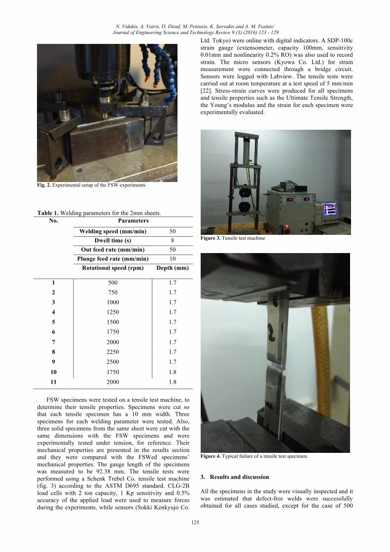
FSW specimens were tested on a tensile test machine, to determine their tensile properties. Specimens were cut so that each tensile specimen has a 10 mm width. Three specimens for each welding parameter were tested. Also, three solid specimens from the same sheet were cut with the same dimensions with the FSW specimens and were experimentally tested under tension, for reference. Their mechanical properties are presented in the results section and they were compared with the FSWed specimens’ mechanical properties. The gauge length of the specimens was measured to be 92.38 mm. The tensile tests were performed using a Schenk Trebel Co. tensile test machine (fig. 3) according to the ASTM D695 standard. CLG-2B load cells with 2 ton capacity, 1 Kp sensitivity and 0.5% accuracy of the applied load were used to measure forces during the experiments, while sensors (Sokki Kenkyujo Co.
Ltd. Tokyo) were online with digital indicators. A SDP-100c strain gauge (extensometer, capacity 100mm, sensitivity 0.01mm and nonlinearity 0.2% RO) was also used to record strain. The micro sensors (Kyowa Co. Ltd.) for strain measurement were connected through a bridge circuit. Sensors were logged with Labview. The tensile tests were carried out at room temperature at a test speed of 5 mm/min [22]. Stress-strain curves were produced for all specimens and tensile properties such as the Ultimate Tensile Strength, the Young’s modulus and the strain for each specimen were experimentally evaluated.
Figure 3. Tensile test machine
Figure 4. Typical failure of a tensile test specimen. 3. Results and discussion All the specimens in the study were visually inspected and it was estimated that defect-free welds were successfully obtained for all cases studied, except for the case of 500

N. Vidakis, A. Vairis, D. Diouf, M. Petousis, K. Savvakis and A. M. Tsainis/ Journal of Engineering Science and Technology Review 9 (3) (2016) 123 - 129
126
rpm. Figure 5 shows the upper surface of the joints. The pin hole, at the end of the FSW process, is present in all joints. The surface of the welded joint at 500 rpm presents excessive defects such as cavities and grooves due to improper flow of the metal caused by insufficient heat input [28]. Small flashes were identified throughout the advancing side of the weld line at rotational speeds from 1000 to 2500 rpm. These flashes are due to the development of excess heat during the experiment. The asymmetry of the FSW process leads to a difference between the temperature on the
advancing and on the retreating side of the specimens. The linear velocity on the perimeter of the shoulder is higher on the advancing side than on the retreating side [29]. The plunge depth of 0.1 mm at rotational speeds of 1750 rpm and 2000 rpm increases the heat generated by the tool. As a result, very small flashes are detected on the advancing side. Semicircular traces were observed but the surface become smoother as the rotational speed increases, which is shown for speeds from 1250 rpm to 2500 rpm.
Fig. 5. AA1050 FSWed specimens at different rotation speeds (Bis: represent test with plunge depth of 0.1 mm; AS: advancing side and RS: retreating side). In figure 6 the 2 mm AA1050 (A91050) reference material stress strain curve of a random specimen is presented as calculated from the tensile tests together with the equivalent curves for the FSWed specimens at various rpms. Table 2 and figure 7 show the calculated tensile properties (ultimate strength, Young’s modulus and strain) average values of the three specimens tested for each welding parameters case and the deviation (joints efficiency) of these values are compared to the base material. In all cases the FSW process of 2mm thick AA1050 alloy at rotational speeds ranging from 500 to 2500 rpm with a constant welding speed of 50 mm/min produced specimens with decreased tensile properties are compared to the parent material. The joint efficiency
reported in this work is in agreement with similar studies in literature, reporting efficiency 70% [26]. The ultimate strength is lower than the base metal (average calculated UTS 107 MPa for the base metal specimens of this study) ranging from 57 to 91 %. The lowest ultimate strength was calculated at the rotational speed of 500 rpm, which is expected due to the presence of defects on the upper-surface of the specimen. The maximum ultimate strength was calculated at the rotational speed of 750 rpm. For higher rpm values up to 1500 rpm the ultimate strength value decreases. At 1750, 2000 and 2250 rpm, the average value of the ultimate strength is the same (70 MPa) and at 2500 rpm it increases (74 MPa). The strain values

N. Vidakis, A. Vairis, D. Diouf, M. Petousis, K. Savvakis and A. M. Tsainis/ Journal of Engineering Science and Technology Review 9 (3) (2016) 123 - 129
127
calculated are lower than the base metal (4.5%) in all cases studied with an efficiency ranging from 25 to 43%. The minimum strain was calculated at 500 rpm and the highest strain value was calculated at 750 rpm. The Young’s modulus values calculated are lower than the base metal,
too, with the welded samples efficiencies ranging between 80 and 100%. At 750 rpm, the FSWeld sample has the same Young’s modulus as the base metal. The minimum value was calculated at 500 and 2250 rpm.
Fig. 6. Stress-strain curves of 2 mm AA1050 FSWed specimens Table 2. Results of the tensile properties of FSWed 2mm thick AA1050 alloy at different welding tool rotational speeds. The experiment welding speed was constant at 50mm/min and the depth was 1.7mm in all cases studied
Parameter Mechanical properties Joint Efficiency (% deviation from the base metal)
Rotational speed (rpm)
Ultimate Strength [MPa]
Strain [%] Young's
Modulus E [GPa]
Ultimate strength Strain Young's
Modulus E
500 61 1.21 75 56,93 24,84 100,00 750 97 2.06 91 91,42 42,53 100,05
1000 88 1.77 88 82,52 36,52 96,62 1250 78 1.76 86 73,49 36,32 94,89 1500 73 1.73 75 68,36 35,73 82,63 1750 70 1.85 77 65,24 38,19 84,94 2000 70 1.68 76 65,39 34,65 84,07 2250 70 1.66 74 65,65 34,15 81,76 2500 74 1.95 79 69,61 40,22 87,06
Base metal 107 4.85 91 - - -

N. Vidakis, A. Vairis, D. Diouf, M. Petousis, K. Savvakis and A. M. Tsainis/ Journal of Engineering Science and Technology Review 9 (3) (2016) 123 - 129
128
Fig. 7. Joint Efficiency of AA1050 Friction Steer Welding The best tensile properties for the FSW experiments conducted in this study with AA1050 at 50 mm/min were obtained at a rotational speed of 750 rpm with joints efficiencies compared to the base material of 91% for the ultimate strength, 43% of the strain and 100% for the young’s modulus. The influence of 0.1 mm plunge depth is also studied for the rotational speeds of 1750 and 2000 rpm. The results are summarized in table 3. These results show that the tensile properties decrease with plunge depth. At 1750 rpm the ultimate strength decreases about 8%, the Young’s modulus decreases about 45% and the strain decreases about 50%. Similar values were calculated for the 2000 rpm case. Table 3. Results of the tensile properties of AA1050 FSWed at 1750 and 2000 rpm with a 0.1 mm plunge depth
Parameters Mechanical properties
Rotational speed (rpm)
Plunge depth (mm)
Welding speed
(mm/min)
Ultimate strength [MPa]
Strain [%]
Young's Modulus E [GPa]
1750 0 50 70 1.85 77
1750bis 0.1 same 64 0.92 41
2000 0 same 70 1.68 76
2000bis 0.1 same 69 0.8 42 4. Conclusions The aim of this study was on the effect of the welding tool rotational speed on the mechanical properties of friction stir welded 2 mm thick AA1050 aluminum alloys butt joints. To evaluate the quality of the welded joint, tensile tests were performed in order to determine mechanical properties such as the Ultimate Tensile Strength, the Young’s Modulus and strain. The results show that 2mm thick AA1050 commercial aluminum alloy sheets can be successfully joined with FSW. Except for the case of welds at the rotational speed of 500 rpm, defect-free welds were obtained in all the rotational speeds tested with a constant welding speed of 50 mm/min. The surface morphology is smoother when increasing the rotational speed. The FSW of 2mm thick AA1050 alloy at rotational speeds ranging from 500 to 2500 rpm with a constant welding speed of 50 mm/min produces welded specimens with decreased tensile properties (ultimate strength, Young’s modulus and strain) compared to the parent material, with the calculated ultimate strength values ranging from 57 to 91 % of the base metal and the calculated strain values ranging from 25 to 43% of the base metal. The minimum strain was calculated at 500 rpm and the highest strain was calculated at 750 rpm. The Young’s modulus decrease as well. However, its values have efficiencies ranging from 80 to 100% of the base metal. The best tensile properties were calculated for the case of FSWed AA1050 at 50 mm/min at a rotational speed of 750 rpm with joints efficiencies of 91% for the ultimate strength and 43% for the strain.
______________________________
References 1. Thomas M.W., Nicholas E.D., Needham J.C., Murch M.G.,
Templesmith P., Dawes C.J., 1991. GB Patent Applications No. 9,125,978.8, December 1991.
2. Vishwanath S Godiganur, Shivakumar Biradar, “Comparison of friction stirs welding technique with conventional welding methods”, IJRET, Volume: 03 Special Issue: 03 | May-2014| eISSN: 2319-1163 | pISSN: 2321-7308
3. B.T. Gibson, D.H. Lammlein, T.J. Prater, W.R. Longhurst, C.D. Cox, M.C. Ballun, et al., Friction stir welding: process, automation, and control, J. Manuf. Process., 16 (2014), pp. 56–73
4. Kumar R, Ghost A, Chattopadhyaya (2014), “Emerging friction stir welding for aluminium and its applications”, Journal of Manufacturing and Industrial Engineering, 14(1-2):1-5
5. Scialpi, L.A.C.D. Filippis, P. Cavaliere, “Influence of shoulder geometry on microstructure and mechanical properties of friction stir welded 6082 aluminum alloy”. Mater Des, 28 (2007), pp. 1124–1129
6. Kumbhar NT, Sahoo SK, Samajdar I, Dey GK, Bhanumurthy K., “ Microstructure and microtextural studies of friction stir welded aluminum alloy 5052”, Mater. Des. 2011; 32: 1657-66.
7. M. Peel, A. Steuwer, M. Preuss, P.J. Withers, “Microstructure, mechanical properties and residual stresses as a function of welding speed in aluminium AA 5083 friction stir welds”, Acta Mater, 51 (2003), pp. 4791–4801
8. K. Elangovan, V. Balasubramanian, “Influences of pin profile and rotational speed of the tool on the formation of friction stir processing zone in AA2219 aluminium alloy”. Mater Sci Eng A, 459 (2007), pp. 7–18
9. Y.H. Zhao, S.B. Lin, L. Wu, F.X. Qu, “The influence of pin geometry on bonding and mechanical properties in friction stir weld 2014 Al alloys”. Mater Lett, 59 (2005), pp. 2948–2952
10. H. Fujii, L. Ling Cui, M. Masakatsu Maeda, K. Kiyoshi Nogi, “Effect of tool shape on mechanical properties and microstructure of friction stir welded aluminum alloys” Mater Sci Eng A, 419 (2006), pp. 25–31
11. S. Jannet P.K. Mathews, R.Raja, “Comparative investigation of friction stir welding and fusion welding of 6061-T6 and 5083-O aluminum alloy based on mechanical properties and microstructure”, Journal of Achievements in Materials and Manufacturing Engineering 61/2 (2013) 181-186.
12. C. Devanathan, A.Suresh Babu, “Effect of Plunge Depth on Friction Stir Welding of Al 6063”, International Conference on Advanced Manufacturing and Automation (INCAMA-2013), March 2013.
13. Mishra, R.S. and Z.Y. Ma, 2005, “Friction stir welding and processing”. Mater. Sci. Eng.: R: Rep., 50: 1-78.
14. M. Di Paola., A. Falchero, S. Spigarelli, “Mechanical and microstructural characterisation of an aluminium friction stir welded butt joint”: Metallurgical Science and Technology 17-21 (accessed on 27 October 2011).
15. T. Srinivasa Rao, G. Madhusudhan Reddy, S. R. Koteswara Rao, “Microstructure and mechanical properties of friction stir welded AA7075−T651 aluminum alloy thick plates” Trans. Nonferrous Met. Soc. China 25(2015) 1770−1778.

N. Vidakis, A. Vairis, D. Diouf, M. Petousis, K. Savvakis and A. M. Tsainis/ Journal of Engineering Science and Technology Review 9 (3) (2016) 123 - 129
129
16. Ivan Galvão, Carlos Leitão, Altino Loureiro, Dulce Rodrigues, “Friction Stir Welding of Very Thin Plates”, Soldag. insp. vol.17 no.1 São Paulo Jan. /Mar. 2012.
17. L. Ceschini, I. Boromei, G. Minak, A. Morri, F. Tarterini, “Effect of friction stir welding on microstructure, tensile and fatigue properties of the AA7005/10 vol.%Al2O3p composite”. Composites Science and Technology, 2007. 67(3-4): p. 605-615.
18. W.Y. Li, T. Fu, L. Hütsch, J. Hilgert, F.F. Wang, J.F. dos Santos, N. Huber, “Effects of tool rotational and welding speed on microstructure and mechanical properties of bobbin-tool friction-stir welded Mg AZ31”, Materials & Design Volume 64, December 2014, Pages 714–720.
19. H. Liu, M. Maeda, H. Fujii, K. Nogi, “Tensile properties and fracture locations of friction-stir welded joints of 1050-H24 aluminum alloy” Journal Of Materials Science Letters 22, 2003, 41– 43.
20. N. Mendes, A. Loureiro, C. Martins, P. Neto, J.N. Pires, “Effect of friction stir welding parameters on morphology and strength of acrylonitrile butadiene styrene plate welds” Materials and Design 58 (2014) 457–464.
21. S. G. Khobragade, Dr. P. M. Khodke, “An effect of Pin less Mild Steel Tool on Friction Stir Welding for Joining Aluminium 6082 Plates” International Research Journal of Engineering and Technology (IRJET) e-ISSN: 2395 -0056 Volume: 02 Issue: 02 | May-2015.
22. D. M. Rodrigues, C. Leitzao, R. Louro, H. Gouveia and A. Loureiro, “High speed friction stir welding of aluminium alloys”, Science and Technology of Welding and Joining Volume 15, Issue 8, 01 November 2010, pp. 676-681.
23. N. A. McPherson, A. M. Galloway, S. R. Cater and S. J. Hambling, “Friction stir welding of thin DH36 steel plate” Science and Technology of Welding and Joining 2013 VOL 18 NO 5 442.
24. Rodrigues DM et al., “Influence of friction stir welding parameters on the microstructural and mechanical properties of AA 6016-T4 thin welds”, J Mater De-sign (2008), doi:10.1016/j.matdes.2008.09.016.
25. Yong-Jai Kwon, Seong-Beom Shim, Dong-Hwan Park, “Friction stir welding of 5052 aluminum alloy plates”, Trans. Nonferrous Met. Soc. China 19(2009) s23−s27.
26. Rao, T.S., Reddy, G.M. & Rao, S.R.K., 2015. Microstructure and mechanical properties of friction stir welded AA7075–T651 aluminum alloy thick plates. Transactions of Nonferrous Metals Society of China, 25(6), pp.1770–1778.
27. Han, B. Huang Y., Lv S., Wana L., Feng J., Fu G., 2013. AA7075 bit for repairing AA2219 keyhole by filling friction stir welding. Materials and Design, 51, pp.25–33.
28. P. Podržaj, B. Jerman, D. Klobčar, “Welding defects at friction stir welding”, Metalurgija 54 (2015) 2, 387-389
29. J. Adamowski, M. Szkodo, Friction Stir Welds (FSW) of aluminum alloy AW6082-T6, Vol. 20 Issues 1-2 January-February 2007