Effect of the coefficient of friction and tightening speed ... · gold-coated abutment screws can...
7
RESEARCH AND EDUCATION Effect of the coefficient of friction and tightening speed on the preload induced at the dental implant complex with the finite element method Haddad Arabi Bulaqi, MSc, a Mahmoud Mousavi Mashhadi, PhD, b Farideh Geramipanah, DDS, MS, c Hamed Safari, DDS, MS, d and Mojgan Paknejad, DDS, MS e One of the most important factors in the survival and success of dental implants is their biomechanical properties. Problems with single tooth implants include screw joint instability, screw loosening, and fracture as the result of fatigue. 1-3 Clinically, screw loosening is more critical in cemented restoration because the intact removal of the crown is problematic in many patients. Additionally, crown loosening may create oblique forces at the implant-abutment connection. 4 Abutment screw loosening was reported in 7% of im- plants restored as single molar or premolar crowns. 5 Also, screw loosening and implant abutment hexagonal rotational misfit appear to be directly correlated. 6 Jemt et al 7 ob- served that the prevalence of screw loosening in the first year of function was 43%. In another study, 8 26% of these screws needed to be retightened within the first year. Bickford 9 described the screw loosening process as occurring in 2 steps. First, external loads such as masti- cation may erode the preload in the screw joint by a Graduate student, Department of Mechanical Engineering, School of Mechanics, University of Tehran, Iran. b Professor, Department of Mechanical Engineering, School of Mechanics, University of Tehran, Iran. c Associate Professor, Implant Research Center, Department of Prosthodontics, School of Dentistry, Tehran University of Medical Sciences, Tehran, Iran. d Assistant Professor, Department of Periodontics, School of Dentistry, Qom University of Medical Sciences, Qom, Iran. e Associate Professor, Dental Research Center, Department of Periodontics, School of Dentistry, Tehran University of Medical Sciences, Tehran, Iran. ABSTRACT Statement of problem. To prevent screw loosening, a clear understanding of the factors influ- encing secure preload is necessary. Purpose. The purpose of this study was to investigate the effect of coefficient of friction and tightening speed on screw tightening based on energy distribution method with exact geometric modeling and finite element analysis. Material and methods. To simulate the proper boundary conditions of the screw tightening process, the supporting bone of an implant was considered. The exact geometry of the implant complex, including the Straumann dental implant, direct crown attachment, and abutment screw were modeled with Solidworks software. Abutment screw/implant and implant/bone interfaces were designed as spiral thread helixes. The screw-tightening process was simulated with Abaqus software, and to achieve the target torque, an angular displacement was applied to the abutment screw head at different coefficients of friction and tightening speeds. The values of torque, preload, energy distribution, elastic energy, and efficiency were obtained at the target torque of 35 Ncm. Additionally, the torque distribution ratio and preload simulated values were compared to theoretically predicted values. Results. Upon reducing the coefficient of friction and enhancing the tightening speed, the angle of turn increased at the target torque. As the angle of turn increased, the elastic energy and preload also increased. Additionally, by increasing the coefficient of friction, the frictional dissipation energy increased but the efficiency decreased, whereas the increase in tightening speed insignificantly affected efficiency. Conclusion. The results of this study indicate that the coefficient of friction is the most influential factor on efficiency. Increasing the tightening speed lowered the response rate to the frictional resistance, thus diminishing the coefficient of friction and slightly increasing the preload. Increasing the tightening speed has the same result as reducing the coefficient of friction. (J Prosthet Dent 2015;113:405-411) THE JOURNAL OF PROSTHETIC DENTISTRY 405
Transcript of Effect of the coefficient of friction and tightening speed ... · gold-coated abutment screws can...
RESEARCH AND EDUCATION
aGraduate stubProfessor, DcAssociate PrdAssistant PreAssociate Pr
THE JOURNA
Effect of the coefficient of friction and tightening speed on thepreload induced at the dental implant complex with the finite
element method
Haddad Arabi Bulaqi, MSc,a Mahmoud Mousavi Mashhadi, PhD,b Farideh Geramipanah, DDS, MS,cHamed Safari, DDS, MS,d and Mojgan Paknejad, DDS, MSe
ABSTRACTStatement of problem. To prevent screw loosening, a clear understanding of the factors influ-encing secure preload is necessary.
Purpose. The purpose of this study was to investigate the effect of coefficient of friction andtightening speed on screw tightening based on energy distribution method with exact geometricmodeling and finite element analysis.
Material and methods. To simulate the proper boundary conditions of the screw tighteningprocess, the supporting bone of an implant was considered. The exact geometry of the implantcomplex, including the Straumann dental implant, direct crown attachment, and abutment screwwere modeled with Solidworks software. Abutment screw/implant and implant/bone interfaceswere designed as spiral thread helixes. The screw-tightening process was simulated with Abaqussoftware, and to achieve the target torque, an angular displacement was applied to theabutment screw head at different coefficients of friction and tightening speeds. The values oftorque, preload, energy distribution, elastic energy, and efficiency were obtained at the targettorque of 35 Ncm. Additionally, the torque distribution ratio and preload simulated values werecompared to theoretically predicted values.
Results. Upon reducing the coefficient of friction and enhancing the tightening speed, the angle ofturn increased at the target torque. As the angle of turn increased, the elastic energy and preloadalso increased. Additionally, by increasing the coefficient of friction, the frictional dissipation energyincreased but the efficiency decreased, whereas the increase in tightening speed insignificantlyaffected efficiency.
Conclusion. The results of this study indicate that the coefficient of friction is themost influential factoron efficiency. Increasing the tightening speed lowered the response rate to the frictional resistance,thusdiminishing the coefficient of friction and slightly increasing thepreload. Increasing the tighteningspeed has the same result as reducing the coefficient of friction. (J Prosthet Dent 2015;113:405-411)
One of the most importantfactors in the survival andsuccess of dental implants istheir biomechanical properties.Problems with single toothimplants include screw jointinstability, screw loosening,and fracture as the resultof fatigue.1-3 Clinically, screwloosening is more critical incemented restoration becausethe intact removal of thecrown is problematic in manypatients. Additionally, crownloosening may create obliqueforces at the implant-abutmentconnection.4
Abutment screw looseningwas reported in 7% of im-plants restored as single molaror premolar crowns.5 Also,screw loosening and implantabutment hexagonal rotationalmisfit appear to be directlycorrelated.6 Jemt et al7 ob-served that the prevalence of
screw loosening in the first year of function was 43%. Inanother study,8 26% of these screws needed to beretightened within the first year.dent, Department of Mechanical Engineering, School of Mechanics, Univepartment of Mechanical Engineering, School of Mechanics, University ofofessor, Implant Research Center, Department of Prosthodontics, Schoolofessor, Department of Periodontics, School of Dentistry, Qom University oofessor, Dental Research Center, Department of Periodontics, School of D
L OF PROSTHETIC DENTISTRY
Bickford9 described the screw loosening process asoccurring in 2 steps. First, external loads such as masti-cation may erode the preload in the screw joint by
ersity of Tehran, Iran.Tehran, Iran.of Dentistry, Tehran University of Medical Sciences, Tehran, Iran.f Medical Sciences, Qom, Iran.entistry, Tehran University of Medical Sciences, Tehran, Iran.
405

Clinical ImplicationsDuring the clinical assembly of implant compo-nents, understanding the effect of the coefficient offriction and tightening speed on preload mightimprove the stability of joint surface characteristicsand tightening speed. This could reduce the inci-dence of screw loosening. Therefore, the use ofelectronic or powered torque controller to controlthe speed of tightening might be useful.
406 Volume 113 Issue 5
producing vibration and micromovement. Second, thepreload falls below a critical value so that the externalforces and vibrations cause the mating threads to turn or“back off.” Interface parameters have an important rolein screw loosening.10 These factors include tighteningtorque,11 functional load,12 preload or clamping force,12
thread embedment or relaxation,13 and misfit.14
The preload created in the implant complex isdependent on the tightening torque, modulus of elas-ticity of materials, coefficient of friction of contact sur-faces,12 speed of tightening, lubrication, componentfitness,13 and screw design parameters,15 such as taperangle, contact length, inner and outer diameters of themembers, and depth of insertion. Friction and preloadare inversely correlated so that with decreasing friction,preload increases.16 Additionally, the manufacturingprocess influences the coefficient of friction. Other in-fluential factors include metallurgical properties, design,quality of surface finish, quantity of wet or dry lubricant,and tightening speed.17,18 The coefficient of friction isenhanced by increasing the material hardness and sur-face roughness, and reduced by lubrication (dry and wet)and tightening speed.17 The humid medium reduces theresistive frictional force by eliminating the shear force.4
Likewise, the sliding speed has an inverse proportionalrelationship with the coefficient of friction.19 Burwellet al20 suggested reducing the frictional force to increasethe sliding speed.
According to first law of thermodynamics, tighteningthe threaded fasteners is essentially an energy transferprocess, wherein the total energy (work done by torque =torque × angular displacement) is converted to 3 forms ofenergy: kinetic, elastic, and frictional dissipation at thetotal duration of the fasteners tightening process. Thetarget torque applied to the implant complex is mostlyabsorbed as conical head friction, thread friction, andpreload. Preload is used to develop the clamping forcethat holds the components together.18,21-23
Budynas and Nisbett24 presented uniform pressureand uniform wear theories for calculating the torque inthe conical region. For d/D (diameter ratio) > 0.6, boththese theories give the same result. In the uniformpressure theory, which is highly applicable for the new
THE JOURNAL OF PROSTHETIC DENTISTRY
conical surface, the pressure distribution in the radialdirection is uniform at the conical surface. Budynas andNisbett24 offered equation (1) to determine the frictionalresistance of conical torque ðTcÞ and equation (2) todetermine the frictional resistance of thread torque ðTthÞ(according to the pressure uniform theory). Wrench tor-que ðTwÞ is the sum of conical and thread torque;equation (3).
Tc=m
3 sin b×D3−d3
D2−d2×F=Kc×F (1)
Tth=dm2×L+ðm×p×dm×sec aÞðp×dmÞ−ðm×L×sec aÞ×F=Kth×F (2)
Tw=Tc+Tth=½Kc+Kth�×F (3)
Tc−w=Tc
Tw=
Kc
Kc+Kth(4)
P=Tw
Kc+Kth=
35Kc+Kth
; (5)
where Tc−w is the ratio of conical torque to the wrenchtorque; F is the preload created in the screw, P is thepreload at the recommended torque of 35 Ncm, m is thecoefficient of friction in the threads and conical head, dis the inner head friction diameter, D is the outer headfriction diameter, b is the cone angle, a is the half angleof the thread, L is the pitch, and dm is the pitchdiameter. The geometric parameters are presented inFigure 1.
Cantwell et al13 stated that the angle of rotation in theapplied torque of 12, 20, and 32 Ncm increased by 73%,76%, and 62%, respectively, in gold-coated titaniumabutments. In another study, Lang et al23 observed thatgold-coated abutment screws can gain more preloadthan ordinary noncoated screws by obtaining lower shearstrength. The increase in preload was 24%, 24%, and26% in the applied torque of 12 Ncm, 20 Ncm, and 32Ncm, respectively.23 Nigro et al4 suggested that lubri-cating abutment screws with saliva may reduce abutmentscrew loosening. In a study conducted by Stüker et al,25
the generated preloads on gold screws (dry lubricant)were 3 times greater than on titanium screws. In a finiteelement analysis study, Jorn et al12 indicated that thefriction coefficient has a major influence on preload. In anexperimental study, Sayed et al26 also found that byincreasing the screw tightening speed in lubricated plainand zinc coated fasteners, the nut factor values and
Bulaqi et al
Wrenchzone
Conicalzone
Threadzone
2α
L
dm
D
d
β
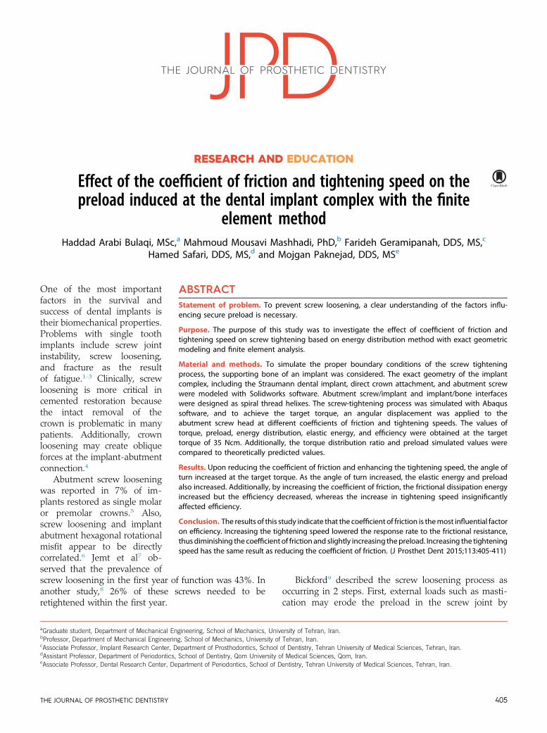
Figure 1. Geometric parameters of implant complex. d=2:015 mm;D=2:6 mm; a=2b= p=6 radian; L=0:4 mm; dm=1:66 mm.
May 2015 407
coefficient of friction decreased slightly. Work by Oliveret al16 found that as the screw tightening speedincreased, the thread and underhead coefficient of fric-tion decreased for lubricated and unlubricated fasteners,but the preload force increased.
Although friction and tightening speed are bothimportant interacting factors influencing the preload,most investigations have only focused on friction, dis-regarding the effect of tightening speed. These studiesare mainly experimental and have investigated the effectof surface characteristics and tightening speed on thecoefficient of friction.13,16,23,25,26 The experimentalmethods are time consuming and costly. Additionally,stress-strain and the force induced in the surroundingbone and implant complex have rarely been calculatedprecisely; therefore, the finite element approach was usedin this investigation. The finite element method (FEM) isadvantageous because it provides accurate, reliable in-formation, as well as a precise representation of complexgeometries and the internal state of stress and othermechanical quantities. However, FEM is approximate,and, although the obtained results should be consideredqualitative, they can be useful in studying various pa-rameters and in further characterization of the problem.Thus FEM provides an appropriate comparison of thequality of stress distribution within the implant complex.
Bulaqi et al
In this study, an attempt is made to investigate the effectof coefficient of friction and tightening speed on preload/clamping from the energy viewpoint.
MATERIAL AND METHODS
For a simulation with proper boundary conditions of thescrew tightening process, the bone surrounding theimplant was considered. A cone beam computed to-mography image of a mandible was used to construct a3-dimensional model of the bone, wherein the corticaland trabecular areas were separated. Then, a computer-aided design file was created by reverse engineeringmethods with Solidworks software (Dassault Systèmes).
To simulate the tightening process of the abutmentscrew within the implant complex, the exact geometry ofthe components was obtained by microscope projectionto allow the resulting clamping and preload force to beinvestigated within the complex. A 4.18 mm Straumanndental implant ITI (SLA 043.031S; Institute Straumann),direct crown attachment (048.642; RN SynOcta goldabutment), and abutment screw (048.356; SynOcta basalscrew) were chosen as the standard model, and themanufacturer’s recommended torque of 35 Ncm was used.
The inner surfaces of the bone and implant bore weregeometrically modeled with a continuous spiral threadedbore, and the outer surfaces of the abutment screw andimplant were geometrically modeled with a continuousspiral threaded helix. The implant thread pitch was1.25 mm, and abutment screw thread pitch was 0.4 mm.Tangential behavior and contact interfaces with a specificcoefficient of friction were defined for the contactingreciprocal interfaces. Four coefficients of friction (m) of0.1, 0.12, 0.16, and 0.20 were assumed in order tocompare the influence of qualitative and quantitativecharacteristics of the surface.27,28 Normal behavior wasmodeled as hard contact. The implant complex was in-serted into the sectioned mandibular bone, upon whichthe boundary conditions were applied. Because completeosseointegration was considered, the bone-implant in-terface was defined as “tie contact.” The implant complexwas assembled within the bone. A “snug tight” conditionbetween the abutment screw-abutment and abutmentscrew-implant were provided so that the initial torquewas zero (Fig. 2).9
Isotropic and homogeneous materials were applied tothe modeling. The mechanical behavior of implantcomponent material was considered in elastic and plasticregions. Additionally, the mechanical properties of thesurrounding bone were only considered in the linearelastic region. The mechanical properties of the materialswere obtained from the manufacturer specifications andthe literature29 and are presented in Table 1.
Abaqus 6.11 software (Dassault Systèmes SimuliaCorp) was used to perform explicit dynamic simulations.
THE JOURNAL OF PROSTHETIC DENTISTRY

Figure 2. Three-dimensional solid model of implant complex assembledwithin bone.
Table 1.Mechanical properties of materials simulated
Materialcomponent
Youngmodulus(GPa)
Poissonratio
Density(g/cm3)
Strength(MPa)
Elongation(%)
Gold abutment* 136 0.37 17.5 765 10 min
Titanium grade 4* 110 0.34 4.5 550 15 min
Cortical bone29 13.7 0.3 3 190 2 max
Trabecular bone29 1.37 0.3 3 10 2 max
*Manufacturer’s specifications.
Table 2.Number of tetrahedral elements for each part in model
Part Number of Elements
Implant (fixture) 78 774
Abutment screw 32 303
Abutment 24 925
Cortical bone 39 700
Trabecular bone 55 947
Figure 3. Finite element models. A, Fixture. B, Abutment. C, Abutmentscrew.
40
35
30
25
20
15
10
5
0.1 0.2 0.3 0.4 0.50
0
SoT = 15 rpmSoT = 30 rpm
CoF =
0.10, 0.12, 0
.16, 0.20
Angle (radian)
To
rqu
e (
Nc
m)
Figure 4.Wrench torque values with respect to angle of turn. SoT: Speedof tightening.
408 Volume 113 Issue 5
An explicit element library and free meshing techniquewith linear geometric order were applied to generatetetrahedral elements. The number of elements for eachof the models are listed in Table 2, and Figure 3 showsthe meshed models of fixture, abutment screw, andabutment.
Upon a complete turn around its axis, the abutmentscrew displaces one pitch along the axis. Torque iscreated by the resultant rotational resistance. Clampingforce and preload are induced by the resistance againstthe axial displacement. Preload manifests as the elon-gation in the abutment screw. In order to achieve therecommended torque in this single-step simulation,angular displacement was applied to the head of theabutment screw at speeds of tightening of 15 and 30rotations per minute (rpm) and under different frictionalconditions.
THE JOURNAL OF PROSTHETIC DENTISTRY
The amounts of wrench torque in terms of the angleof turn were investigated under different frictional con-ditions and rotational speeds. To validate the obtaineddata, the predicted and simulated ratio of conical torqueto wrench torque and preload were compared. Finally,the energy distribution and the transfer ratio of the totalenergy to the frictional dissipation, elastic, and kineticenergies were derived, and the efficiency and amount ofelastic energy were obtained under different frictionalconditions.
RESULTS
The wrench torque-angle curve is shown in Figure 4 atvarious frictional conditions and rotational speeds. Thevalues of turn angle and conical torque at the targettorque are listed in Table 3. Additionally, Figure 5Acompares the simulated and predicted values of conicalto wrench torque ratio ðTc−w; equation [4]), Figure 5Bcompares simulated and predicted values of preload at
Bulaqi et al

Table 3. Turn angle and conical torque values at target torque for eachcoefficient of friction and speed of tightening
Coefficientof Friction
Angle (radian) Conical Torque (Ncm)
15 rpm 30 rpm 15 rpm 30 rpm
0.10 0.47 0.54 26.04 25.51
0.12 0.39 0.47 26.39 25.97
0.16 0.30 0.37 27.77 26.50
0.20 0.24 0.31 27.09 26.88
0.9
0.75
0.6
0.45
0.3
0.15
0.05 0.1 0.15 0.2 0.25 0.30
0
Coefficient of Friction
Ra
tio
of
Tco
nic
al t
o T
wre
nc
h
Equation (4)
Tightening speed = 30 rpm
Tightening speed = 15 rpm
Equation (5)
Tightening speed = 30 rpm
Tightening speed = 15 rpm
750
600
450
300
0.1 0.15 0.2 0.25 0.3150
0.05
Coefficient of Friction
Pre
loa
d (
N)
B
A
Figure 5. Comparison of predicted and simulated values. A, Conical towrench torque ratio. B, Preload.
Table 4. Simulated and predicted values of conical to wrench torqueratio and preload for each coefficient of friction and speed of tightening
Coefficientof Friction
Ratio of Tc to Tw ðTc−wÞ Preload (N)
Simulated
Predicted
Simulated
Predicted15 rpm 30 rpm 15 rpm 30 rpm
0.10 0.744 0.729 0.735 574 593 577
0.12 0.754 0.742 0.748 489. 504 488
0.16 0.765 0.757 0.764 377 393 375
0.20 0.774 0.768 0.774 312 320 304
B
A
1
0.8
0.6
0.4
0.2
0.1 0.2 0.3 0.4 0.50
0
Angle (radian)
En
erg
y R
ati
o
Kin/Tot energy
Fri/Tot energy
Ela/Tot energy
(CoF, SoT) = (0.20, 15)
(CoF, SoT) = (0.12, 15)
(CoF, SoT) = (0.20, 30)
(CoF, SoT) = (0.12, 30)
1
0.8
0.6
0.4
0.2
0.1 0.2 0.3 0.4 0.50
0
Angle (radian)
En
erg
y R
ati
o
Figure 6. A, Transfer energy distribution (CoF=0.12, SoT=30 rpm). B,Ratio of frictional dissipation to total energy. CoF: Coefficient of friction;SoT: Speed of tightening.
May 2015 409
the target torque (equation [4]), and their values atdifferent frictional conditions and rotational speeds arepresented in Table 4.
Figure 6A shows the ratio of elastic, kinetic, andfrictional dissipation energies to the total energy (m=0:12,SoT=30 rpm). At the beginning of the screw tighteningprocess, the ratio of kinetic energy to the total energy(Kin/Tot) equaled 1 unit, and the ratio of frictionaldissipation and elastic energy to the total energy (Fri/Totand Ela/Tot) was zero. The proportional values of energyratios at recommended torque were 0.2% (Kin/Tot),88.75% (Fri/Tot), and 11.05% (Ela/Tot). In Figure 6B, theratio of frictional dissipation energy to the total energy
Bulaqi et al
was compared at the coefficients of friction of 0.12 and0.2 and at tightening speeds of 15 and 30 rpm. The valuesof these ratios, efficiency, total energy, and elastic energyat the recommended torque are reported in Table 5.
DISCUSSION
Screw retained components are used to convert torque totension. Upon turning an abutment screw with a wrench,the external work (total energy) is applied on the implantcomplex. During the screw tightening process, this
THE JOURNAL OF PROSTHETIC DENTISTRY

Table 5. Energy and efficiency values for different coefficients of frictionand speed of tightening
Coefficient ofFriction, Speedof Tightening
Fri/TotEnergy(%)
Efficiency(%)
TargetTorque(Ncm)
Angleof Turn(radian)
TotalEnergy(Ncm)
ElasticEnergy(Ncm)
(0.12, 15) 88.93 10.82 35 0.39 13.65 1.48
(0.20, 15) 90.85 8.65 35 0.24 8.4 0.73
(0.12, 30) 88.75 11.05 35 0.47 16.45 1.82
(0.20, 30) 90.72 8.88 35 0.31 10.85 0.96
410 Volume 113 Issue 5
energy is converted into kinetic, frictional dissipation,and elastic energies, which are distributed differentlyduring the process.9,21 Geometric parameters, surfacequality, and frictional response are the key factors influ-encing these distributions. For a specific geometry of theimplant complex, the geometric parameters are constant,but the coefficient of friction could be varied by dry andwet lubrication and also tightening speed.4,13,15-17,19 Atthe start of the turning process, the kinetic energy wasequal to the total energy, and at the end of process (attarget torque), the amount of kinetic energy was almostzero (Fig. 6A).
Frictional dissipation energy is the result of energydissipation in the conical and thread zones.9,18,23 Themeasured torque is the result of the rotational resistanceforce that is induced by the coefficient of friction in these2 zones.
Elastic energy is stored in the form of elastic defor-mation or preload in the abutment screw and providesthe holding power to clamp the parts together. Thisenergy is directly related to the square root of preload.9,30
By defining efficiency as the ratio of elastic energy (usefulenergy) to total energy, preload can be increased byreducing the frictional dissipation energy as a result ofdecreasing the coefficient of friction. Because most of thetotal energy is converted into heat through the frictionaldissipation energy,9 efficiency is estimated to be less than10% at most mechanical complexes31; the kinetic energyat the recommended torque is negligible.
According to the modern theory of friction, betweendry metal surfaces or with a dry lubricant, local minutewelds occur at the rough peaks of surfaces in contactwith each other. In other words, adhesion and slidingfriction force can limit the motion between the 2 sur-faces.20 Burwell et al20 presented 2 methods of studyingthe effects of speed on the frictional force at a dry metalsurface: (1) increase of the shear strain rate at the local ofwelding junctions and (2) the length of required time fora junction of full strength to be formed. Additionally,according to hydrodynamic theory for a wet frictioncondition, by increasing the speed, the contact pressurebetween the surfaces increases and thus film thicknessbetween these surfaces increases, thereby reducing thecoefficient of friction.24
The effect of coefficient of friction and tighteningspeed can be assessed in 3 ways: torque-angle
THE JOURNAL OF PROSTHETIC DENTISTRY
relationship, ratio of conical torque to wrench torqueðTc−w), and energy distribution. In accordance with thetorque-angle curve shown in Figure 4, as the coefficientof friction increases, the frictional force or the rotationalresistance force also increases, leading to a higher slopeof the curve. With the increase of the curve slope, thetarget torque was achieved at a lower angle of turn(Table 3).13
By increasing the tightening speed, the length ofrequired time for junction deformation at a specific angleof turn was reduced.20 In other words, by decreasing theresponse rate to the frictional resistance, the friction forceand rotational resistance force decrease, leading to alower torque-angle curve slope. To achieve the targettorque, such a reduction leads to greater angular rotationas a result of greater tightening speed (Table 3).16
The created torque within the conical zone has adifferent distribution that is dependent on geometricparameters such as height and angle of the cone.13,15 Thedata presented in Table 3 imply that for a cone angle of15 degrees, the torque distribution is almost 75% for theconical zone and 25% for the thread zone. Merz et al32
reported that these distributions for ITI implants with acone angle of 8 degrees were 91% for the conical zoneand 9% for the thread zone.32
The values predicted by Equation 4 show that bydecreasing the coefficient of friction, the ratio of Tc to Twdecreased (Fig. 5A); this was confirmed by the simulateddata (Table 4). Considering that the increase of tight-ening speed was accompanied by a decrease in the Tc−wvalues, it can be concluded that increasing the tighteningspeed has the same result as reducing the coefficient offriction.16,19
According to the results predicted by Equation 5 andthe simulated data in Figure 5B, the coefficient of frictionand preload are inversely correlated.12,16,19 Additionally,the simulated data further indicate that as the tighteningspeed increases, the preload also increases. As a result,the tightening speed and preload are directly related, inthat with an increase in speed, the coefficient of frictiondecreases.4,23,25 By comparing the difference of gainedpreload under various frictional conditions, it can beconcluded that the tightening speed effect increased atlower coefficient of friction (Table 4).16,19
A better understanding of the screw tightening pro-cess can be achieved through the transferred energydistribution (Fig. 6A). The area under the torque-anglecurve is proportional to the total energy required totighten the fastener. By multiplying the target torque bythe turn angle, the required total energy for tighteningcan be approximately calculated. The ratio of frictionaldissipation energy to total energy was enhanced at thetarget torque by increasing the coefficient of friction,thereby decreasing efficiency (Table 5), whereas thisratio decreased for a specific angle of turn because of the
Bulaqi et al

May 2015 411
smaller area under the torque-angle curve. Tighteningspeed has a negligible effect on efficiency; however, ifincreased, the elastic energy and thus preload would alsoincrease (Fig. 6B).
CONCLUSION
Within the limitations of this FEM analysis, decreasingthe coefficient of friction resulted in decreased frictionaldissipation energy and a subsequent increase in turnangle, thus increasing the efficiency enhanced preloadand elastic energy. Torque distribution at the conicalzone was approximately 75% and at the thread zoneapproximately 25%. By increasing the tightening speed ata specific turn angle, the length of required time for ajunction of full strength to form decreased, leading to asubsequent decrease in the coefficient of friction andfriction force. Higher tightening speed showed no sig-nificant effect on efficiency. However, as the elastic en-ergy increased, the preload also increased. Increasing thetightening speed has the same result as reducing thecoefficient of friction. To achieve the specified targettorque, speed of tightening has more of an effect at alower coefficient of friction. Increasing the tighteningspeed and reducing the coefficient of friction are 2influencing factors in enhancing preload and thusimproving stability and preventing screw loosening.
REFERENCES
1. Worthington P, Bolender CL, Taylor TD. The Swedish system of osseointe-grated implants: problems and complications encountered during a 4-yeartrial period. Int J Oral Maxillofac Implants 1987;2:77-84.
2. Zarb GA, Schmitt A. The longitudinal clinical effectiveness of osseointegrateddental implants: the Toronto study. Part III: Problems and complicationsencountered. J Prosthet Dent 1990;64:185-94.
3. Glantz PO, Rangert B, Svensson A, Stafford GD, Arnvidarson B, Randow K,et al. On clinical loading of osseointegrated implants. A methodological andclinical study. Clin Oral Implants Res 1993;4:99-105.
4. Nigro F, Sendyk CL, Francischone CE Jr, Francischone CE. Removal torqueof zirconia abutment screws under dry and wet conditions. Braz Dent J2010;21:225-8.
5. Simon RL. Single implant-supported molar and premolar crowns: a ten-yearretrospective clinical report. J Prosthet Dent 2003;90:517-21.
6. Binon PP. The effect of implant/abutment hexagonal misfit on screw jointstability. The International journal of prosthodontics 1996;9:149-60.
7. Jemt T, Lekholm U, Grondahl K. 3-year followup study of early singleimplant restorations ad modum Branemark. Int J Periodontics RestorativeDent 1990;10:340-9.
8. Jemt T, Laney WR, Harris D, Henry PJ, Krogh PH Jr, Polizzi G, et al.Osseointegrated implants for single tooth replacement: a 1-year report from amulticenter prospective study. Int J Oral Maxillofac Implants 1991;6:29-36.
9. Bickford JH. An introduction to the design and behavior of bolted joints. 3rded. New York: Marcel Dekker; 1995. p. 515-64.
10. Aboyoussef H, Weiner S, Ehrenberg D. Effect of an antirotation resistanceform on screw loosening for single implant-supported crowns. J ProsthetDent 2000;83:450-5.
Bulaqi et al
11. Jaarda MJ, Razzoog ME, Gratton DG. Effect of preload torque on theultimate tensile strength of implant prosthetic retaining screws. Implant Dent1994;3:17-21.
12. Jorn D, Kohorst P, Besdo S, Rucker M, Stiesch M, Borchers L. Influence oflubricant on screw preload and stresses in a finite element model for a dentalimplant. J Prosthet Dent 2014.
13. Cantwell A, Hobkirk JA. Preload loss in gold prosthesis-retaining screws as afunction of time. Int J Oral Maxillofac Implants 2004;19:124-32.
14. Farina AP, Spazzin AO, Consani RL, Mesquita MF. Screw joint stability afterthe application of retorque in implant-supported dentures under simulatedmasticatory conditions. J Prosthet Dent 2014;111:499-504.
15. Bozkaya D, Muftu S. Mechanics of the taper integrated screwed-in (TIS)abutments used in dental implants. J Biomech 2005;38:87-97.
16. Oliver M, Jain V. Effect of tightening speed on thread andunder-head coefficient of friction. Journal of ASTM International 2006;3:45-52.
17. Burguete RL, Johns RB, King T, Patterson EA. Tightening characteristicsfor screwed joints in osseointegrated dental implants. J Prosthet Dent1994;71:592-9.
18. Barbosa GS, Silva-Neto JP, Simamoto-Junior PC, Neves FD, Mattos Mda G,Ribeiro RF. Evaluation of screw loosening on new abutment screws and aftersuccessive tightening. Braz Dent J 2011;22:51-5.
19. Rabinowicz E. Friction and wear of materials. 2nd ed. New York: Wiley; 1995.20. Burwell JT, Rabinowicz E. The nature of the coefficient of friction. J Appl Phys
1953;24:136-9.21. Breeding LC, Dixon DL, Nelson EW, Tietge JD. Torque required to loosen
single-tooth implant abutment screws before and after simulated function.International J Prosthodont 1993;6:435-9.
22. Tzenakis GK, Nagy WW, Fournelle RA, Dhuru VB. The effect of repeatedtorque and salivary contamination on the preload of slotted gold implantprosthetic screws. J Prosthet Dent 2002;88:183-91.
23. Lang LA, Kang B, Wang RF, Lang BR. Finite element analysis to determineimplant preload. J Prosthet Dent 2003;90:539-46.
24. Budynas RG, Nisbett JK. Shigley’s mechanical engineering design. 9th ed.New York: McGraw-Hill; 2011. p. 845-55.
25. Stüker RA, Teixeira ER, Beck JC, da Costa NP. Preload and torque removalevaluation of three different abutment screws for single standing implantrestorations. J Appl Oral Sci 2008;16:55-8.
26. Sayed A, Nassar SG, Ramanathan M. Effect of tightening speed on thetorque-tension and wear pattern in bolted connections. J Press VesselTechnol 2006;129:426-40.
27. Haack JE, Sakaguchi RL, Sun T, Coffey JP. Elongation and preload stressin dental implant abutment screws. Int J Oral Maxillofac Implant 1995;10:529-36.
28. Bowden FP, Tabor D. The friction and lubrication of solids. Oxford New York:Clarendon Press ; Oxford University Press; 2001.
29. Borchers L, Reichart P. Three-dimensional stress distribution around adental implant at different stages of interface development. J Dent Res1983;62:155-9.
30. Beer FP. Mechanics of materials. 6th ed. New York:McGraw-Hill; 2011. p. 694-9.31. Cornwell JF. Some observation on friction in screw threads. Wear 1981;67:
329-39.32. Merz BR, Hunenbart S, Belser UC. Mechanics of the implant-abutment
connection: an 8-degree taper compared to a butt joint connection. Int J OralMaxillofac Implant 2000;15:519-26.
Corresponding author:Dr Mojgan PaknejadDental Research CenterTehran University of Medical SciencesNorth Amir-Abad, TehranIRANEmail: [email protected]
AcknowledgmentsThe authors thank the Amirkabir University of Technology’s high-performancecomputing research center (HPCRC) for computing support of this research.
Copyright © 2015 by the Editorial Council for The Journal of Prosthetic Dentistry.
THE JOURNAL OF PROSTHETIC DENTISTRY