Effect of Tether Routing and Anchor Location on Child ... · This report describes a series of 16...
28
DOT HS 812 467 December 2017 Effect of Tether Routing And Anchor Location on Child Restraint Kinematics
Transcript of Effect of Tether Routing and Anchor Location on Child ... · This report describes a series of 16...
DOT HS 812 467 December 2017
Effect of Tether Routing And Anchor Location on Child Restraint Kinematics
Disclaimer
This publication is distributed by the U.S. Department of Transportation, National Highway Traffic Safety Administration, in the interest of information exchange. The opinions, findings, and conclusions expressed in this publication are those of the authors and not necessarily those of the Department of Transportation or the National Highway Traffic Safety Administration. The United States Government assumes no liability for its content or use thereof. If trade or manufacturers’ names or products are mentioned, it is because they are considered essential to the object of the publication and should not be construed as an endorsement. The United States Government does not endorse products or manufacturers.
Suggested APA Format Citation:
Klinich, K. D., Manary, M. A., & Orton, N. R. (2017, December). Effect of tether routing and anchor location on child restraint kinematics (Report No. DOT HS 812 467). Washington, DC: National Highway Traffic Safety Administration.

i
Technical Report Documentation Page 1. Report No.DOT HS 812 467
2. Government Accession No. 3. Recipient's Catalog No.
4. Title and SubtitleEffect of Tether Routing and Anchor Location on Child Restraint Kinematics
5. Report DateDecember 2017 6. Performing Organization Code
7. Author(s)Klinich, Kathleen D., Manary, Miriam A., Orton, Nichole R.
8. Performing Organization Report No.UMTRI-2013-27
9. Performing Organization Name and AddressUniversity of Michigan Transportation Research Institute 2901 Baxter Rd. Ann Arbor, MI 48109
10. Work Unit No. (TRAIS)
11. Contract or Grant No.
12. Sponsoring Agency Name and AddressNational Highway Traffic Safety Administration 1200 New Jersey Avenue SE. Washington, DC 20590
13. Type of Report and Period CoveredFinal, October 2012-August 2013
14. Sponsoring Agency Code
15. Supplementary Notes
16. Abstract
A series of 16 sled tests were performed to examine the effect of tether routing with respect to the vehicle head restraint on the kinematics of the Hybrid III 3-year-old ATD secured in two forward-facing harnessed child restraints. The main outcome of interest was whether a particular tether routing provided a safety benefit by reducing head excursions. Two different child restraints were used, one with a single strap tether and the other with a V-style tether. The single strap was routed either under or over the head restraint, while the V-style tether was routed either under or around the head restraint. Three different tether anchor locations were evaluated, representing locations on the roof, rear filler panel, or the lower vehicle seatback. Two different vehicle seats were mounted to the FMVSS 213 sled buck. One was the outboard second-row seat from the 2011 Ford Explorer, while the other was the center second-row seat from the 2011 Jeep Grand Cherokee. Child restraints were installed with lower anchors in the Explorer seat and the seatbelt in the Grand Cherokee.
The specific tether routing did not have an effect on head excursion. Rather, head excursion increased as the length of tether webbing between the tether attachment point on the child restraint and the tether anchor hardware increased. The results of these tests suggest that the tether routing providing the shortest distance to the vehicle tether anchor be recommended, as long as that routing allows the user to achieve a tight tether installation. This study is limited by the use of only two different vehicles and two different child restraints for testing.
17. Key WordTether, LATCH, usability, child restraint installation
18. Distribution StatementAvailable to the public from the National Technical Information Service www.ntis.gov
19. Security Classif. (of this report) 20. Security Classif. (of this page) 21. No. of Pages28
22. Price
Form DOT F 1700.7 (8-72) Reproduction of completed page authorized

ii
EXECUTIVE SUMMARY This report describes a series of 16 tests that examine the effect of tether routing with respect to the vehicle head restraint on the kinematics of a crash test dummy representing a 3-year-old child secured in forward-facing harnessed child restraints. Two different child restraints were used, one with a single strap tether and the other with a V-style tether. Three different tether anchor locations were evaluated, representing locations on the roof, rear filler panel, or the lower vehicle seatback. Two different vehicle seats were mounted; one was the outboard second-row seat from the 2011 Ford Explorer, while the other was the center second-row seat from the 2011 Jeep Grand Cherokee. Child restraints were installed with lower anchors in the Explorer seat and the seat belt in the Grand Cherokee. The specific tether routing did not have an effect on head excursion. Rather, head excursion increased as the length of tether webbing between the tether attachment point on the child restraint and the tether anchor hardware increased. The results of these tests suggest that the tether routing providing the shortest distance to the vehicle tether anchor be recommended, as long as that routing allows the user to achieve a tight tether installation.

iii
TABLE OF CONTENTS List of Figures ......................................................................................................................................... iv
List of Tables ........................................................................................................................................... v
Introduction ............................................................................................................................................ 1
Methods.................................................................................................................................................. 2
Vehicle Survey ..................................................................................................................................... 2
Selecting Seats for Testing ................................................................................................................... 4
Child Restraint Selection ...................................................................................................................... 6
Test Matrix .......................................................................................................................................... 6
Results .................................................................................................................................................. 12
Discussion ............................................................................................................................................. 18
Conclusions ........................................................................................................................................... 19
References ............................................................................................................................................ 20

iv
LIST OF FIGURES Figure 1. Distribution of vehicles by directed tether routing for each style of outboard
head restraint. ...................................................................................................................... 4 Figure 2. Distribution of vehicles by directed tether routing for each style of center
head restraint. ..................................................................................................................... 4 Figure 3. Outboard (left) and center (right) head restraints in the Ford Explorer. ................................ 5 Figure 4. Outboard (left) and center (right) head restraints in the Jeep Grand Cherokee. .................... 5 Figure 5. ComfortSport (left) and Marathon (right) installed in Ford Explorer outboard seat. .............. 6 Figure 6. Side view of “back” tether anchorage location representing a tether mounted
to the rear filler panel. .......................................................................................................... 8 Figure 7. Side view of the “low” tether anchorage location representing a
seatback-mounted tether, plus a rear-view close-up of the hardware. .................................. 8 Figure 8. Side view of the “high” tether anchorage location representing a
roof-mounted tether. ........................................................................................................... 9 Figure 9. Measuring slack in tether post-test. .................................................................................... 11 Figure 10. Variation in length of “active” tether webbing for each test condition
(ComfortSport=left eight bars, Marathon=right eight bars). ................................................ 14 Figure 11. Peak tether force (N) versus the tether length from CRS attachment to tether anchor. ....... 14 Figure 12. Peak head excursion versus the tether length from CRS attachment to tether anchor. ....... 15 Figure 13. Tether load measured in tests with Marathon. ................................................................... 16 Figure 14. Tether load measured in tests with ComfortSport. .............................................................. 16 Figure 15. Axial neck loads in tests run with Marathon. ....................................................................... 17 Figure 16. Axial neck loads in tests run with ComfortSport. ................................................................. 17

v
LIST OF TABLES Table 1. Examples of head restraint styles for the outboard and center positions. ............................. 3 Table 2. Test conditions ..................................................................................................................... 7 Table 3. Examples of tether strap routings used with each child restraint and vehicle seat. ............. 10 Table 4. Summary of peak test results ............................................................................................. 13 Table 5. Amount of tether slack measured in 4 studies of volunteers installing
forward-facing child restraints ............................................................................................ 18
1
INTRODUCTION Several recent studies of child restraint installation errors indicated that a common mistake when installing tethers was to route the tether with respect to the head restraint in a manner other than that prescribed by the vehicle manufacturer (Klinich et al., 2010, 2012, 2013a, 2013b). In some cases, volunteer test subjects attached the tether hook to the correct hardware in the vehicle at the correct orientation and were able to tighten the tether, but the installation was considered to be in error because the subject did not follow the vehicle manufacturer’s tether routing instructions (Klinich et al., 2012, 2013a).
Vehicle manufacturer’s directions for tether routing vary considerably. The routing can depend not only on the features of the head restraint, but on the location of the tether anchorage and may be different for adjacent seating positions. Tether anchorages are most commonly located on the rear filler panel, vehicle seatback, floor, or roof. Vehicle manufacturers direct users to route the tether strap under, over, around, inboard, or outboard of the head restraint. In some cases, users are allowed or directed to remove the head restraint when using a tether.
The variety of tether anchorage locations and tether routing directions can lead to confusion during child restraint installation. While tether anchorage locations may be restricted by the features of the vehicle, the number of options for routing the tether strap could potentially be simplified across vehicles. If a particular tether routing provides a safety benefit by reducing head excursion more than other routings, it could be recommended for use in most vehicles. If all tether routings provide a similar reduction in head excursion, users could use any routing as long as they can get the tether tight and the anchor hardware meets Federal Motor Vehicle Safety Standard (FMVSS) 225 strength tests.
The objectives of this study were to perform sled testing to determine if particular method of routing the tether strap offers a safety benefit in terms of reduced head excursion.

2
METHODS Vehicle Survey
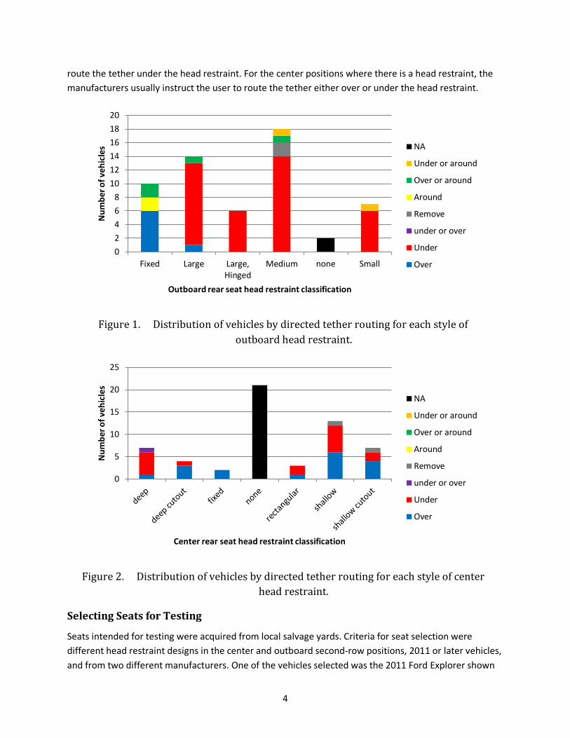
To begin, 57 popular late model vehicles were surveyed at local dealerships to identify trends in second row head restraint designs, as well as to check user manual instructions for routing tether straps with respect to head restraints. Compared to the head restraint designs seen in a recent vehicle survey of 2010-2011 vehicles (Klinich et al., 2012), the designs of the outboard and center head restraints now tend to differ more than in past years. In addition, many vehicles specify different tether strap routing for the center and outboard seating positions. Table 1 shows examples of different styles of head restraint found in the vehicles surveyed, as well as a term used to categorize each style of head restraint for the purposes of this study.

3
Table 1. Examples of head restraint styles for the outboard and center positions.
Outboard Center
Larg
e
Deep
Larg
e hi
nged
Shal
low
Med
ium
Rect
angu
lar
Smal
l
Deep
cuto
ut
Fixe
d
Shal
low
Cut
out
Figure 1 and Figure 2 show the number of vehicles with each type of head restraint, broken down by the recommended tether routing. For the outboard seating positions, the most common direction is to
4
route the tether under the head restraint. For the center positions where there is a head restraint, the manufacturers usually instruct the user to route the tether either over or under the head restraint.
Figure 1. Distribution of vehicles by directed tether routing for each style of outboard head restraint.
Figure 2. Distribution of vehicles by directed tether routing for each style of center head restraint.
Selecting Seats for Testing
Seats intended for testing were acquired from local salvage yards. Criteria for seat selection were different head restraint designs in the center and outboard second-row positions, 2011 or later vehicles, and from two different manufacturers. One of the vehicles selected was the 2011 Ford Explorer shown
02468
101214161820
Fixed Large Large,Hinged
Medium none Small
Num
ber o
f veh
icle
s
Outboard rear seat head restraint classification
NA
Under or around
Over or around
Around
Remove
under or over
Under
Over
0
5
10
15
20
25
Num
ber o
f veh
icle
s
Center rear seat head restraint classification
NA
Under or around
Over or around
Around
Remove
under or over
Under
Over

5
in Figure 3. This vehicle has a large head restraint in the outboard second-row seating positions and a shallow head restraint in the center second-row position. The directions state to route the tether under the outboard head restraints but over the center seating position. The tether anchors for this vehicle are located near the bottom of the vehicle seatback.
Figure 3. Outboard (left) and center (right) head restraints in the Ford Explorer.
The second vehicle selected for testing was the 2011 Jeep Grand Cherokee. The second-row seats of the Grand Cherokee have large hinged head restraints in the outboard positions, and a shallow cutout head restraint in the center position. The directions indicate that tethers should be routed under the head restraint in the outboard positions and over the head restraint in the center position.
Figure 4. Outboard (left) and center (right) head restraints in the Jeep Grand Cherokee.

6
Child Restraint Selection
Two different child restraints were selected for testing to allow evaluation of single-strap and V-style tethers. V-style tethers are most commonly found on Britax child restraints, so the Britax Marathon was chosen for assessing this style of tether. The other convertible was the Graco ComfortSport that uses a single-strap tether. Another difference between these two products is that the Marathon construction is more rigid, while the ComfortSport is more flexible. As shown in Figure 5, the overall height of the ComfortSport places it lower relative to the head restraint compared to the Marathon. However, the tether is attached to the Marathon at a distance of 56 cm (22 in) when measured from the floor, while the tether is attached to the ComfortSport at a location 61 cm (24 in) above the floor. Finally, the Marathon has push-on lower connectors while the ComfortSport has hook-on lower connectors.
Figure 5. ComfortSport (left) and Marathon (right) installed in Ford Explorer outboard seat.
Test Matrix
The matrix of test conditions is shown in Table 2. Half of the tests were run with the outboard Ford Explorer seat, while the other half were run with the center seat of the Jeep Grand Cherokee. With the Ford Explorer seats, child restraints were secured with LATCH belt using the standard 15 lb pretension.

7
Hardware was constructed to approximate lower anchor locations found in the vehicle. With the Jeep Grand Cherokee seats, child restraints were secured with 15 lb lap belt tension and 2-4 lb shoulder belt tension. Belt anchors approximate those found in vehicle.
The seats were mounted to the FMVSS 213 test buck so the fore-aft location of the H-point measured in an exemplar vehicle aligned with the fore-aft location of the H-point of the FMVSS 213 sled buck. This allowed excursion measurements calculated from video analysis during this test series to be comparable to the excursions measured in standard FMVSS 213 testing.
Table 2. Test conditions
TestID Seat CRS Routing Tether Anchorage
Tether webbing length: CRS to TA (mm)
NT1307 Ford Explorer ComfortSport under back 419 NT1308 Ford Explorer Marathon under back 445 NT1309 Ford Explorer Marathon around back 394 NT1310 Ford Explorer ComfortSport over back 660 NT1311 Ford Explorer ComfortSport under low 699 NT1312 Ford Explorer Marathon around low 648 NT1313 Ford Explorer Marathon under high 654 NT1314 Ford Explorer ComfortSport over high 610 NT1315 Jeep Grand Cherokee Marathon under back 419 NT1316 Jeep Grand Cherokee ComfortSport under back 419 NT1317 Jeep Grand Cherokee ComfortSport over back 464 NT1318 Jeep Grand Cherokee Marathon around back 445 NT1319 Jeep Grand Cherokee Marathon under low 724 NT1320 Jeep Grand Cherokee ComfortSport over low 756 NT1321 Jeep Grand Cherokee ComfortSport under high 635 NT1322 Jeep Grand Cherokee Marathon around high 584
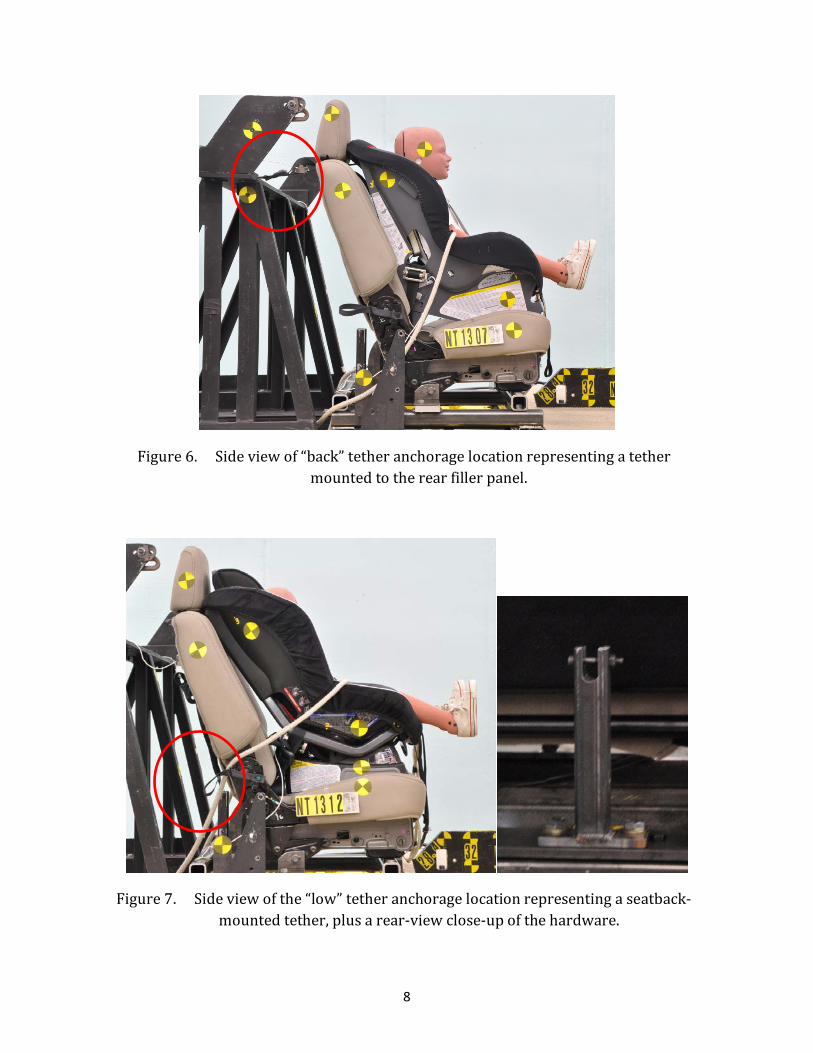
Three different tether anchorage locations were used. The back location approximates a tether anchorage location on the rear filler panel commonly located in sedans. The standard tether anchorage fixture used in FMVSS 213 testing was used to approximate this tether anchorage location as shown in Figure 6. The low tether anchorage location represents a tether anchor located on the bottom of the vehicle seatback. For this test series, a fixture was constructed as shown in Figure 7 that places the anchorage in the general area of the lower seatback. Its location is approximately 350 mm forward and 500 mm lower than the standard FMVSS 213 tether anchorage. The third tether anchorage location represents a “high” roof-mounted tether as shown in Figure 8. Its location is approximately 25 mm rearward and 450 mm higher than the standard FMVSS 213 tether anchorage.
8
Figure 6. Side view of “back” tether anchorage location representing a tether mounted to the rear filler panel.
Figure 7. Side view of the “low” tether anchorage location representing a seatback-mounted tether, plus a rear-view close-up of the hardware.

9
Figure 8. Side view of the “high” tether anchorage location representing a roof-mounted tether.
Three different tether strap routings were used, with examples shown for each child restraint and vehicle seat in Table 3. With both child restraints, the tether straps could be routed under the head restraint. During testing, the head restraint was placed in the lowest position possible after the tether strap was routed underneath it. For the other test conditions, the ComfortSport tether strap was routed over the head restraint, while the Marathon tether strap was routed around the head restraint. Because of the spacing of the Marathon’s tether attachment points relative to the widths of the head restraints, the Marathon tether strap could not be routed over the head restraint and tightened in a stable manner.
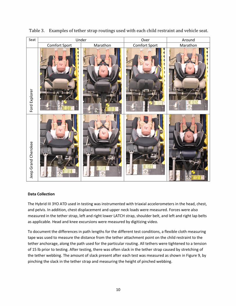
10
Table 3. Examples of tether strap routings used with each child restraint and vehicle seat.
Seat Under Over Around Comfort Sport Marathon Comfort Sport Marathon
For
d Ex
plor
er
Je
ep G
rand
Che
roke
e
Data Collection
The Hybrid III 3YO ATD used in testing was instrumented with triaxial accelerometers in the head, chest, and pelvis. In addition, chest displacement and upper neck loads were measured. Forces were also measured in the tether strap, left and right lower LATCH strap, shoulder belt, and left and right lap belts as applicable. Head and knee excursions were measured by digitizing video.
To document the differences in path lengths for the different test conditions, a flexible cloth measuring tape was used to measure the distance from the tether attachment point on the child restraint to the tether anchorage, along the path used for the particular routing. All tethers were tightened to a tension of 15 lb prior to testing. After testing, there was often slack in the tether strap caused by stretching of the tether webbing. The amount of slack present after each test was measured as shown in Figure 9, by pinching the slack in the tether strap and measuring the height of pinched webbing.

11
Figure 9. Measuring slack in tether post-test.

12
RESULTS Table 4 summarizes the peak measured response values for each test. Text is color-coded by tether strap routing; italics signify tests run with the Jeep while bold text indicates those run with the Marathon. All tests fell below the allowable limits for HIC and chest 3-ms clip.
The head restraint did not move during any of the tests between its original and post-test position. However, in some cases when routing the tether strap under the head restraint, the head restraint could not be locked into the lowest position because of interference with the tether strap adjustor.
Figure 10 plots the length of the tether from child restraint attachment point to tether anchor for each condition. For the ComfortSport tests shown on the left, the length was longer going over the Ford head restraint compared to going under it when using the back (B) tether location, but the lengths were fairly similar when going over and under the Jeep head restraint. The lengths were similar when going over the Ford head restraint to the high (H) location and under the Jeep head restraint to the high location with the ComfortSport. Lengths were also similar when routing under the Ford head restraint to the low (L) location and over the Jeep head restraint to the low location. For the Marathon, the differences in tether lengths between going under or around the head restraint were generally smaller than the differences between going under or over the head restraint with the ComfortSport. With the Marathon, all four routings to the back tether location were similar; the routings under the head restraints to the high or low tether locations took more tether length to reach than those going around to the same tether locations.
The peak tether load versus the active tether length is shown in Figure 11. Trendlines are included for each child restraint, with the ComfortSport values generally higher than the Marathon values. As the distance between the child restraint attachment point and the tether increases, the peak tether load decreases. The range of values is larger for the ComfortSport.
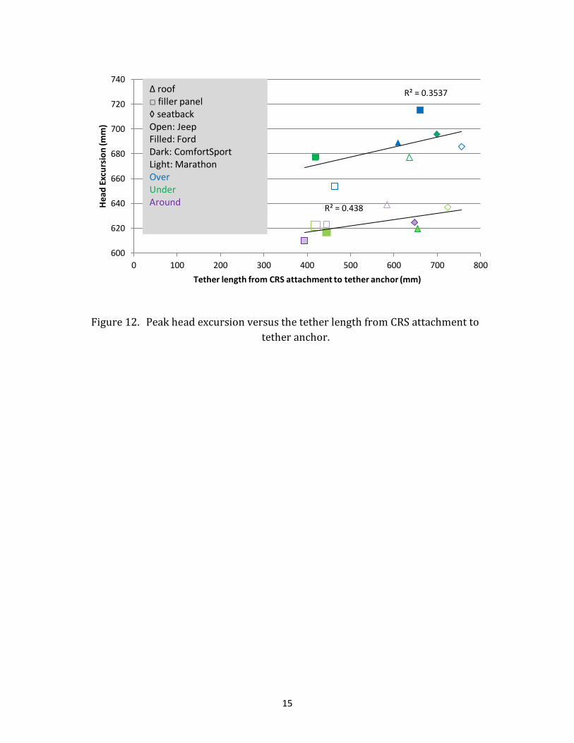
The peak forward head excursion versus the tether length is shown in Figure 12. Trendlines are included for each child restraint. As the distance between the child restraint and tether anchor increases, the head excursion increases. Among the Marathon tests, the difference between the largest and smallest head excursion is 29 mm, while the range for the ComfortSport is 61 mm.
The tether load histories are shown in Figure 13 for the Marathon and Figure 14 for the ComfortSport. The peak tether loads for the Marathon are more consistent across different test conditions than those for the ComfortSport. The Marathon tether is advertised as having energy-absorbing features, which may be responsible for the somewhat oscillatory nature of the tether load response. Although the tether loads look different for the two child restraints, the axial neck loads, shown in Figure 15 and Figure 16, show smaller differences in peak values. When restrained by the Marathon, the ATD’s neck initially goes into compression before increasing to a peak ranging from 1,402 to 2,127 N. The ComfortSport range of peak neck axial tension is comparable at 1,644 to 2,046 N.

13
Table 4. Summary of peak test results
TestID HIC36 Head 3ms clip (g)
Chest 3 ms clip (g)
Neck Force Res (N)
Neck Moment Res (Nm)
Chest Displ (mm)
Left LATCH Or Belt (N)
Right LATCH Or Belt (N)
Tether Force (N)
Shoulder Belt Force (N)
Head Ex (mm)
Knee Ex (mm)
Post-test Tether Slack (mm)
NT1307 599 69.5 39.3 2062 14.4 25.4 1969 2450 3900 677 696 25 NT1310 732 63.8 42.5 1999 16.4 22.9 4154 4259 2306 715 737 20 NT1311 630 72.4 39.7 2142 14.2 25.4 3184 3017 2158 696 722 0 NT1314 694 67.9 43.6 2095 17.4 20.3 3877 3858 3267 689 732 45 NT1316 759 61.5 47.2 1864 19.3 22.9 1786 1458 2777 3812 678 723 50 NT1317 658 62.4 40.1 1902 16.1 22.9 1617 1475 3037 4036 654 689 25 NT1320 766 72.7 47.0 1895 19.1 20.3 1908 2034 1151 4023 686 737 0 NT1321 727 58.9 43.3 1758 21.1 20.3 1836 1545 2359 5036 677 734 25 NT1308 548 50.7 49.6 1679 18.2 15.2 1587 1667 1772 617 689 100 NT1309 455 50.8 50.9 1578 19.3 15.2 1444 1463 1928 610 703 100 NT1312 615 68.1 55.2 2329 20.2 20.3 1787 2078 937 625 744 76 NT1313 571 69.0 54.8 1948 19.8 17.8 1626 1888 1729 620 709 50 NT1315 596 53.7 40.8 1758 13.3 17.8 2489 1316 2041 3991 622 713 75 NT1318 576 56.5 51.7 1775 16.1 17.8 2522 1504 1645 4126 623 725 89 NT1319 695 62.6 48.3 1944 16.7 17.8 1692 823 1044 5540 637 741 50 NT1322 724 74.2 46.0 1887 16.3 15.2 2770 2108 2297 4769 639 744 100
Under, over, around; Jeep, Ford; ComfortSport, Marathon

14
Figure 10. Variation in length of “active” tether webbing for each test condition (ComfortSport=left eight bars, Marathon=right eight bars).
Figure 11. Peak tether force (N) versus the tether length from CRS attachment to tether anchor.
0
100
200
300
400
500
600
700
800
F, B F, B J, B J, B F, H J, H F, L J, L F, B F, B J, B J, B F, H J, H F, L J, L
Dist
ance
from
CRS
att
achm
ent t
o te
ther
an
chor
(mm
)
Vehicle, Tether location
Over
Under
Around
R² = 0.6503
R² = 0.3525
0
500
1000
1500
2000
2500
3000
3500
4000
4500
0 100 200 300 400 500 600 700 800
Teth
er l
oad
(N)
Tether length from CRS attachment to tether anchor (mm)
Δ roof□ filler panel◊ seatbackOpen: JeepFilled: FordDark: ComfortSportLight: MarathonOverUnderAround
15
Figure 12. Peak head excursion versus the tether length from CRS attachment to tether anchor.
R² = 0.3537
R² = 0.438
600
620
640
660
680
700
720
740
0 100 200 300 400 500 600 700 800
Hea
d Ex
curs
ion
(mm
)
Tether length from CRS attachment to tether anchor (mm)
Δ roof□ shelf◊ seatbackOpen: JeepFilled: FordDark: ComfortSportLight: BritaxOverUnderAround
Δ roof□ filler panel◊ seatbackOpen: JeepFilled: FordDark: ComfortSportLight: MarathonOverUnderAround
Δ roof□ filler panel◊ seatbackOpen: JeepFilled: FordDark: ComfortSportLight: MarathonOverUnderAround

16
Figure 13. Tether load measured in tests with Marathon.
Figure 14. Tether load measured in tests with ComfortSport.
-500
0
500
1000
1500
2000
2500
3000
3500
4000
4500
0 0.02 0.04 0.06 0.08 0.1 0.12
Teth
er Lo
ad (N
)
Time (sec)
F, CS, U, B
F, CS, O, B
F, CS, U, L
F, CS, O, H
J, CS, U, B
J, CS, O, B
J, CS, O, L
J, CS, U, H
Thick: Ford Explorer (F)Thin: Jeep Grand Cherokee (J)Solid: Back (B)Dash: Low (L)Dot: High (H)Green: Under (U)Blue: Over (O)Purple: Around (A)

17
Figure 15. Axial neck loads in tests run with Marathon.
Figure 16. Axial neck loads in tests run with ComfortSport.
-750
-250
250
750
1250
1750
2250
0 0.05 0.1 0.15 0.2 0.25
Nec
k Fo
rce
Z
Time (sec)
F, CS, U, B
F, CS, O, B
F, CS, U, L
F, CS, O, H
J, CS, U, B
J, CS, O, B
J, CS, O, L
J, CS, U, H
Thick: Ford Explorer (F)Thin: Jeep Grand Cherokee (J)Solid: Back (B)Dash: Low (L)Dot: High (H)Green: Under (U)Blue: Over (O)Purple: Around (A)

18
DISCUSSION These tests were performed to estimate whether a particular direction for routing a tether with respect to a head restraint was more effective at limiting head excursion. The results did not suggest that a particular routing was best. However, they do suggest that the shortest routing between the child restraint tether attachment point and the tether anchorage leads to the lowest head excursion. These results are consistent with earlier tests performed on forward-facing harnessed child restraints that focused on the relative benefits of different tether attachment locations on the child restraint (Brown et al., 1995, LeGault, Gardner & Vincent, 1997). These studies indicated that child restraint attachment points higher on the seatback generally showed that tether strap attachment points located higher on the child restraint were more effective at reducing head excursion compared to attachment points lower on the child restraint. The results were attributed to the location of the tether attachment relative to the center of gravity of the child. However, the lower attachment points would also lead to a longer length of tether webbing. The previous studies did not vary the actual tether anchorage location and did not usually include a head restraint on the test buck so the effect of routing the tether with respect to the test buck to different tether locations was usually not considered.
One caveat of these results is that the differences among test conditions were not large. In typical FMVSS 213 testing, achieving head excursions repeatable within 12 mm under the same test conditions is normal. When child restraints are tested with and without using a tether, the difference in head excursion are usually about 100 mm. So the range of head excursion values seen with the Marathon of 29 mm is just over double the typical range of repeatability, and the maximum difference in head excursions seen with the ComfortSport of 61 mm is smaller than not substantially larger than the typical range of repeatability.
The differences in head excursion resulting from using different tether routing and different tether anchor locations may be smaller than differences in excursion caused by not tightening the tether during installation. In four volunteer installation test series (sponsored by the NHTSA or the IIHS), the amount of slack measured in forward-facing installations with tether use are summarized below. Average slack in the tether ranged from 7 to 15 mm, with the standard deviation ranging from 16 to 42 mm, and maximum slack ranging from 102 to 305 mm. In addition, failure to use the tether when recommended was common in these volunteer tests, as well as studies of tether use in the field (Jermakian & Wells 2010, Decina & Lococo 2007).
Table 5. Amo
unt of tether slack measured in 4 studies of volunteers installing forward-facing child restraints
Tether Slack (mm) Study # tethers attached Mean Std Min Max CRS Features 44 15 37 0 229 CRS Labels/Manuals 69 7 16 0 102 Vehicle Features 133 9 40 0 305 LATCH Usability 72 14 42 0 254

19
The benefits of requiring the shortest tether routing to have less active length of tether webbing that can be stretched must be balanced with the potential for allowing slack in the tether during installation. In the studies in which volunteers performed forward-facing child restraint installations in different vehicles, some vehicles placed the tether anchor close to the vehicle head restraint on the filler panel, such that the tether could not physically be tightened if it was routed under the head restraint, although it could be tightened if the subjects were allowed to route the tether over the head restraint. In other vehicles, there was sufficient distance between the child restraint and tether anchor to allow the tether to be tightened. However, when routing the tether under the head restraint, the tether adjustment hardware was placed under the head restraint, and the volunteers could not achieve a tight installation because it was difficult to adjust.
The main limitation of this study is that it only considered two child restraint systems and two vehicle seats. The deformation characteristics of head restraints and seatbacks likely affect interaction with tethers differently in different vehicles. In addition, despite substantially different head restraint designs, the head excursions were very similar when comparing the two vehicle seat types under the same routing and anchorage location conditions.
The tether anchors used in this study were rigid and intended to provide repeatable non-deforming anchors for multiple tests. Tether anchors in vehicles may deform more than those measured in the current test series, which could affect results. During the tests, none of the head restraints shifted from their original position. In addition, none of the head restraint mounting posts were damaged.
One of the child restraints tested employs a tether that has energy-absorbing features. This produced lower peak tether loads in the tests with the Marathon compared to those run with the ComfortSport. However, the measured neck axial loads had a similar range of peak values across test conditions when run with the ComfortSport and Marathon, and the range of head excursions was also similar for both child restraints tested. When comparing the amount of post-test slack in the tether, the Marathon generally had higher levels of slack compared to the ComfortSport, which is likely due to its energy-absorbing features.
CONCLUSIONS This small scale study suggests that there is not a particular method of routing the tether that provides the greatest safety benefit in terms of reduced head excursion. Rather, the lowest head excursions were associated with the routing and tether locations that involved the shortest amount of tether webbing between the tether anchor and the attachment point on the child restraint.
In general, the preferred directions for routing tethers would direct users to route the tether along a path that minimizes the distance to the tether anchor. However, the shortest distance to the tether (i.e., under the head restraint to the rear filler panel or seatback) may make it difficult for the user to adequately tighten the tether if the adjustor mechanism ends up near or below the head restraint. If the user cannot tighten the tether, slack in the tether may offset the benefit of having a shorter distance to the tether anchor and less stretch in the tether webbing. If this is the case, directions for tether routing that allow removal of the headrest may provide the most beneficial tether installation.

20
REFERENCES Brown, J., Kelly, P., Griffiths, M., Tong, S., Pak, R., & Gibson, T. (1995). The performance of tethered and untethered forwarding child restraints. In: Proceedings of the International Research Council on the Biomechanics of Impact Conference on the Biomechanics of Impact, September 13-15, 1995, Brunnen, Switzerland, p. 61-74.
Decina, L. E., & Lococo, K. H. (2007). Observed LATCH use and misuse characteristics of child restraint systems in seven states. Journal of Safety Research 38:271-281.
Jermakian, J. S., & Wells, J. K. (2010). Observed use of tethers in forward-facing child restraint systems. Inj Prev. 17(6): 371-4.
Klinich, K. D., Manary, M. A., Flannagan, C. A. C., Ebert, S. M., Malik, L. A., Green, P. A., & Reed, M. P. (2010). Labels, instructions, and features of convertible child restraint systems (CRS): Evaluating their effects on CRS installation errors (Report No. UM-2010-37). Ann Arbor, MI: University of Michigan Transportation Research Institute.
Klinich, K. D., Manary, M. A., Flannagan, C. A. C., Malik, L. A., & Reed, M. P. (2010). Effect of vehicle features on CRS installation errors (Report No. UM-2010-38). Ann Arbor, MI: University of Michigan Transportation Research Institute.
Klinich, K. D., Flannagan, C. A. C., Manary, M. A., Moore, J.L. (2012). LATCH usability in vehicles (Report No. UMTRI-2012-7). Ann Arbor, MI: University of Michigan Transportation Research Institute.
Klinich, K. D., Manary, M. A., Flannagan, C. A., Ebert, S. M., Malik, L. A., Green, P. A., & Reed, M. P. (2013). Effects of child restraint features on installation errors. Applied Ergonomics. doi:pii: S0003-6870(13)00077-X. 10.1016/j.apergo.2013.04.005.
Klinich, K. D., Flannagan, C. A.C., Jermakian, J. S., McCartt, A. T., Manary, M. A., Moore, J. L., & Wells, J. K. (2013). Vehicle LATCH system features associated with correct child restraint installations. Traffic Injury Prevention, 14(5):520-31. doi: 10.1080/15389588.2012.701030.
Legault, F., Gardner, W., & Vincent, A. (1997) The effect of top tether strap configurations on child restraint performance (Technical Paper 973304). Warrendale, PA: SAE International.

DOT HS 812 467 December 2017
11788-122017-v3