EFFECT OF TEMPERING TEMPERATURE AND … EFFECT OF TEMPERING TEMPERATURE AND TIME ON STRENGTH AND...
63
1 EFFECT OF TEMPERING TEMPERATURE AND TIME ON STRENGTH AND HARDNESS OF DUCTILE CAST IRON This thesis Submitted In Partial Fulfilment of The requirement For the Degree of Master of Technology ( DUAL DEGREE ) In Metallurgical and Materials Engineering By RAVINDRA KUMAR (Roll no. 710MM1165) Under the Guidance of Dr. Sudipta Sen 2015
Transcript of EFFECT OF TEMPERING TEMPERATURE AND … EFFECT OF TEMPERING TEMPERATURE AND TIME ON STRENGTH AND...

1
EFFECT OF TEMPERING TEMPERATURE AND TIME ON
STRENGTH AND HARDNESS OF DUCTILE CAST IRON
This thesis Submitted
In Partial Fulfilment of The requirement For the Degree of
Master of Technology ( DUAL DEGREE )
In Metallurgical and Materials Engineering
By
RAVINDRA KUMAR
(Roll no. 710MM1165)
Under the Guidance of
Dr. Sudipta Sen
2015

2
CERTIFICATE
This is to certify that the thesis qualified, “Effect of Tempering
Temperature and Time on Strength and Hardness of Ductile Cast
Iron” submitted by Ravindra Kumar (710MM1165) for requirements
Master of Technology degree in metallurgical & Materials Engineering at
National Institute of Technology, Rourkela is a genuine work carried out
under my guidance and supervision.
Dr. Sudipta Sen
Associate professor
Department of Metallurgical and Materials Engineering
National Institute of Technology Rourkela-769008, Odisha

3
ACKNOWLEDGEMENT
I would like to express my sincere gratitude to Dr. Sudipta Sen, Department of
Metallurgical and Materials Engineering for assigning me the project “Effect of
Tempering Temperature and Time on Strength and Hardness of Ductile Cast
Iron” His positive behavior and regular guidance made it possible to understand
this project better . It is not possible to acknowledge suitable his important
contribution of our knowledge and time given selflessly in proceeding with my
project work. I have received infinite support and good guidance from him.
I am very grateful to our all professors of Metallurgical and materials engineering
department. And Mr. Ranjan Kumar Behera, Ph.D. Scholar, and all my
Classmate and my M.Tech friends to given excellent support for helping me
throughout the project and providing me with lot of information and support as and
when I required. I am also thank full to L&T Kansbahal, India. For providing
project materials
Ravindra Kumar
Department of Metallurgical and Materials Engineering
National Institute of Technology Rourkela-769008, Odisha

4
CONTENTS
TOPICS PAGE NO.
Certificate 2
Acknowledgement 3
Abstract 6
List of figures 7-8
List of table 9
CHAPTER 1. INTRODUCTION OF DUCTILE IRON 10-11
1.1 Production of ductile cast iron. …………………………………………………12-14
1.2 Types of cast iron and ductile cast iron. ………………………………………..15-17
1.3 Effect chemical composition of ductile cast iron. ……………………..……….18-19
1.4 Different Microstructure of ductile cast iron. ………………………………….19-20
1.5 Ductile or brittle behavior of ductile cast iron. …………………………………20-21
Chapter 2. A BRIEF REVIEW OF PREVIOUS WORK ON DUCTILE CAST IRON 22-28
Chapter 3. PROPERTIES AND APPLICATION OF DUCTILE CAST IRON
3.1 Properties of ductile cast iron. …………………………………………………...29-30
3.2 Effect of alloying elements on the properties of ductile cast iron. ……………...30-31
3.3 Applications of Ductile cast iron. ……………………………………………….. 32
CHAPTER 4. HEAT TREATMENT OF DUCTILE CAST IRON
4.1. Austenitizing. …………………………………………………………………….34
4.2. Tempering. ………………………………………………………………………35
4.3. Annealing. ………………………………………………………………………..35
4.4. Quench Hardening. …………………………………………………………….35-3
…
…
.
1

5
CAHPTER 5: EXPERIMENTAL PROCEDURE
5.1: Specimen preparation………………………………………………………………37
5.2: Heat treatment processes……………………………………………………………38
5.3: Tensile test and factrography………………………………………………………39
5.4: Polishing and Etching………………………………………………………………39
5.5: Nodular and Nodularity count……………………………………………………40-44
5.6: Microstructure study……………………………………………………………….44
5.7: Study of mechanical properties……………………………………………………45
5.7.1: Hardness testing…………………………………………………………………45
5.7.2: Impact testing……………………………………………………………………46
5.7.3: Wear test…………………………………………………………………………47
5.7.4: Surface mechanism after wear test……………………………………………….47
5.8: X-Ray Diffraction………………………………………………………………….48
CHAPTER 6: RESULT AND DISCUSSION………………………………………49-58
CHAPTER 7: CONCLUSION……………………………………………………….59
CHAPTER 8: REFERENCES………………………………………………………60-63
…
1

6
ABSTRACT
The use of ductile cast iron is as an engineering materials has been increase day by day.it is widely
used in manufacturing industry. It have excellent combination of mechanical properties due to
same heat treatment process at different time and temperature. It have an excellent combination of
tensile strength, wear resistance, good corrosion resistance, good ductility, toughness, impact
strength, by using different types of heat treatment process. The effects of tempering temperature
and time on the mechanical properties of ductile cast iron is investigated in the current work. The
all sample were austenitized at 900°C for 120 minutes and then quenched in mineral oil at room
temperature. After quenching the specimens were tempered at 400°C and 200°C for 60min, 90min,
and 120min, respectively. In the tempering temperature range of 200°C - 400°C, there is sudden
increase in impact strength, ductility and toughness of the materials, as the temperature and time
increase. The Ultimate tensile strength drops initially, and hardness of materials will also depends
on amount of matrix phase of martensitic and retain-austenitic/ferrite and graphite nodules. In this
work alloying elements also effected the microstructure of the specimen. And due to increase
tempering time the amount of martensitic phase will decrease and austenitic phase will increase,
austenitic phase is softer then martensitic so hardness will decrease. and sample treated to ball on
plate wear tester under 20N load at constant speed 10rpm with different times 10min, 20min,
30min for sliding distance 4mm track diameter respectively of same sample. Weight loss was
observed in all sample after wear test, the wear resistance was calculated according to the ASTM
G 65 standard, and the result showed that in all cases, when the nodules count and nodularity
increase the wear resistance decrease and when tempering time and temperature increase the wear
resistance will also effected. And by XRD investigate the different matrix and volume fraction,
peak analysis.
7
LIST OF FIGURES: Figure Content Page
no.
Figure 1.1 G.F. Fisher Method for production of ductile iron 14
Figure 1.2 Microstructure of ductile iron and gray iron 19
Figure 1.5 Ductile to Brittle transition occurs as temperature increases 21
Figure 4.1 Conventional Quench & Tempering Process 34
Figure 4.2: CCT diagram showing annealing, normalizing and quenching, martensite 36
Figure 5.1 Specimen Specifications 37
Figure 5.2 Microstructure of 200°C at 1h before etching and threshold value of that image 40
Figure 5.3 Investigation of 200°C at 1h by using metal power image analyzer software 40
Figure 5.4 Microstructure of 200°C at 1.5h before etching and threshold value of that image 41
Figure 5.5 Investigation of 200°C at 1.5h by using metal power image analyzer software 41
Figure 5.6 Microstructure of 200°C at 2h before etching and threshold value of that image 41
Figure 5.7 Investigation of 200°C at 2h by using metal power image analyzer software 42
Figure 5.8 Microstructure of 400°C at 1h before etching and threshold value of that image 42
Figure 5.9 Investigation of 400°C at 1h by using metal power image analyzer software 42
Figure 5.10 Microstructure of 400°C at 1.5h before etching and threshold value of that image 43
Figure 5.11 Investigation of 400°C at 1.5h by using metal power image analyzer software 43
Figure 5.12 Microstructure of 400°C at 2hr before etching and threshold value of that image 43
Figure 5.13 Investigation of 400°C at 2hr by using metal power image analyzer software 44
Figure 5.6.1 Measurement of hardness test by using Vickers hardness test 45
Figure 5.7.1 Charpy V-Notch Impact Testing Specimen Measurements 46
Figure 5.7.2 Charpy V-Notch Impact Testing Instrument 46

8
Figure 5.7.3 (a) Ducom TR-208-M1 Ball on plate type wear monitor 47
Figure 5.7.3 (b) Schematic diagram of pin on disc wear test machine 47
Figure 7.1 Effect of tempering Time On Elongation %, Impact Strength, Tensile Strength, Y.S. 50
Figure 7.2 Microstructure of different tempered sample and amount of phases 51-52
Figure 7.3 Fractography Image of tempered specimen a) at 200°C in 60 min b) at 200°C in 90 min
c) at 200°C in 120 min d) at 400°C in 60 min e) at 400°C in 90 min f) at 400°C in 120
53
Figure 7.4 % weight loss of different tempered sample. 54
Figure 7.5 Fractography image of wear surface of different tempered sample 55-57
Figure 7.6 XRD analysis data of tempered sample with different matrix phases 58

9
LIST OF TABLES:
Table Page
Table 5.1 Chemical composition of specimens in wt. % 37
Table 6.1 Mechanical properties of specimen at 200°C and 400°C at different time 49
Table 6.2 Amount of matrix presence in specimen at different time and temperature 51

10
CHAPTER 1
1:- INTRODUCTION Ductile cast Iron is likewise called to as “Spheroidal Graphite” iron or “nodular Iron” it is a kind
of cast iron designed in 1943 by Keith Millis. While highest of the diversities of cast iron have brittle
behavior. But ductile iron has much extra impact strength and fatigue resistance, because of its
nodular graphite inclusions [1]. It was produced 1948 in American Foundry men’s Society Annual
Conference. J.W. Bolton, taking at the 1943 Convention of the American Foundry men’s Society
(AFS) going to make cast iron - an as-cast "gray iron" with mechanical properties equivalent or
better to Malleable Iron [3]. A couple of weeks after the fact, in the International Nickel Company
Research Laboratory, Keith Dwight Millis made a ladle addition of magnesium (as a copper-
magnesium alloy) to cast iron and supported Bolton's idealism –after casting they absorbed the
solidified castings not contained flakes, but rather about perfect spheres of graphite which is called
graphite nodules[4]. After five years, at the 1948 AFS Convention, Henton Morrogh of the British
Cast Iron Research Association reported that they also produced of spherical graphite successfully
in hypereutectic gray iron by the mixing of small amounts of cerium. Ductile Iron is also called a
high strength nodular cast iron. It have excellent engineering properties. Ductile cast iron have
spherical graphite nodules in its internal/inward structure. It have uncommon combination of
properties because the graphite formed as spheroids nodules slightly than flakes as in grey iron.
The shape flakes of graphite create more stress concentration at a points or edges flakes within the
metal phases and the rounded structure of the nodules less stress concentration so, thus preventing
the formation of cracks and providing the higher ductility properties that gives also the same
specifics alloys[6]. This method of hardening is gotten by including A Small amount of Mg & Ce
or both they are Maine reasons the flake graphite to take on a spheroidal shape.

11
The including Mg reacts with S or O in the molten condition or liquid cast iron and because of
that reaction graphite will formed on shape. It’s have good fluidity, good wear resistance, excellent
machinability, high strength, reasonable toughness and ductility [7]. It’s Application in as like
Door lock, Crankshafts, gears and rollers, pressure castings such as valve and pump bodies, and
huge press rolls. Due to presence of high amount of carbon and silicon element of ductile iron give
the casting procedure with a couple of profits, but the graphite nodules have only a significant
effect on the mechanical properties of the metal. Ductile iron shows a linear stress-strain relation,
a significant variety of yield strengths. Different types of Castings are made in an extensive variety
of sizes with segments that can be either thick or thin [11]. Flexibility of Ductile Iron, are provides
the greatest combination of overall properties. That adaptability is particularly apparent in the area
of mechanical properties whereas Ductile Iron proposals the formation of different type of designs
with the option of choosing high ductile metal, with have more than 18% elongation, or high
strength, with tensile strengths exceeding (825 MPa). Austempered Ductile Iron (ADI),
suggestions more mechanical properties and wear resistance, and it have tensile strengths
exceeding (1600 MPa) [21]. When compared to Ductile Iron with steel castings, it also suggestions
additional cost savings. Its most commercial cast metals, Malleable Iron and steel reduction in
volume during solidification, therefore it require connected stores (feeders or risers) of liquid metal
to counterbalance and prevent the formation of interior or outside shrinkage imperfections.
The formation of graphite nodules/flack during solidification are Maine reason an internal
expansion properties of Ductile Iron [26]. It may be provided cast free of important shrinkage the
elimination or reduction of feeders can be obtained by only appropriately design castings. This
reduction necessities for increases feed metal and productivity of Ductile Iron increases and
decreases energy requirements of material and it resulting in considerable cost savings process.

12
1.1 Production of ductile cast iron
Ductile cast iron is also known as nodular cast iron or spheroidal graphite cast iron. It is made by
treating molten iron of proper composition of Mg & Ce or both before casting. They help to
formation of graphite in the form of separate nodules in its place of inter connected flakes [28]. It
have good fluidity, good wear resistance, excellent machinability, high strength, reasonable
toughness and ductility.
Following factor is also important for production of ductile cast iron
Desulphurization: Sulphur helps in the development of graphite flakes. But for ductile
cast iron we want graphite nodules. Therefor at producing ductile cast iron the Sulphur
content should be low as like less < 0.1% in raw materials. Therefor during melting Sulphur
should be eliminate by addition of a desulphurising agent as like calcium carbide or soda
ash.
Nodularizing: Small amount of Magnesium is mixed with bath to stalemate up Sulphur
and oxygen and then drastically change in the graphite growth mechanism. When
Magnesium treat with oxygen it form highly stable MgO and which is floats on the molten
surface and can be removed easily [19]. It reduces levels from of 90-135ppm to about 15-
35ppm.when Magnesium treated with Sulphur than it form less stable MgS. Because of
magnesium have low solubility and volatile nature of in the metal and, reaction can become
reversible if Si is added for additional deoxidation. Other things Cerium is also forms
highly stable oxides with Sulphur and Oxygen and it’s have less volatile than Mg.
Addition of Mg is done when the materials melt is at 1500°C but Mg vaporizes at 1100°C.
Magnesium is lighter then it floats on bath and it’s more reactive then it burn off at the

13
surface. For saving Mg we generally added as Ni-Mg, Ni-Si-Mg alloy or magnesium coke
to reduce chemical reaction. Therefore magnesium plays an important role in the
manufacture of ductile cast iron [15]. After nodulising treatment inoculants like Mg
providing their nodulising effect on the graphite structure therefor the graphite nodules can
be formed.
Inoculation: before the metal molt or either during pouring the small amount of
inoculation of cast iron added. Therefore Inoculation increases the precipitation and
consequent growth of graphite. This effect is increasing the degree of nucleation growth of
cast iron. It can be assumed that high levels formation of graphite structure whilst low
levels of formation of either mottled structure or white irons [15].
When cooling rate increases, the requirement for a high level of nucleation is also increases
and segment size decreases. The main purpose of addition of inoculation, is an important
in maintaining good nodule shape and also increase more numbers of nodules. Graphite
are not more effective inoculants for ductile cast irons. Basically based on silicon all
inoculants are more effective. Ferrosilicon generally used in foundry grade, containing
about 75% silicon. This alloy also must contain small amounts of Al and calcium, the
amounts of required are about 1.5-2.05 aluminum and approx. about calcium 0.3-1.0%.
The inoculating effect initially increases as the amount of inoculants is increased in the
materials. This partially reimburses for their increased cost and has the advantage of
reducing the amount of silicon contained.

14
Solidification of Ductile cast iron:
Solidification of Ductile cast iron is continuously related with correct under cooling.
Graphite nuclei growth gradually and then it enclosed by austenite. The formation of
austenite and graphite corresponds of eutectic point at the eutectic temperature. Austenite
gets supersaturated position with carbon. And at the graphite/austenite interface new
equilibrium stage is established. The extra carbon diffuses towards the graphite nodule
which is precipitates out.
Fig 1.1: G.F. Fisher Method for production of ductile iron
15
1.2 Types of Cast iron and ductile cast iron
Types of cast iron
Cast irons mostly contain more than 2% Carbon with multiplicity of alloying elements.
Classification of cast iron is done on the basis of the presence of their mechanical properties and
fracture surface and their microstructure with a different matrix phases. basically two class of cast
irons historically, one having a gray fracture and another having a white fracture, which is called
gray cast iron and white cast iron respectively [6]. Those cast irons having both gray and white
properties are called mottled iron. Other type of cast irons have been developed in 19 century
which have their name on their mechanical property, such as malleable iron and ductile iron. More
recently in ductile cast iron have compacted graphite iron and austempered ductile iron have been
introduced.
There are four elements which lead to the different types of cast irons namely,
1) The Amount of carbon content,
2) Different type of alloy elements content
3) The Amount of impurity content,
4) The cooling rate and the heat treatment after casting.
These factors control the composition as well as the form of parent matrix phase present.
Classification of different types of cast iron.
1. Gray cast iron:
2. White cast iron:
3. Malleable cast iron:
4. Ductile cast iron:

16
1. Gray cast irons:
Gray cast iron is the very popular type of cast iron and it is easily found. It has a high amount of
graphite flakes therefor it have gray crack surface. Carbon is more stable than carbide form at
graphite form. At a cooling time if it’s controlled cooling rate and negligible alloying addition then
carbon gets precipitated out as graphite flakes. Gray cast iron has high amount of Si content
therefor it is help the formation of graphite flakes during solidification. It have minor ductility
properties but it is very useful because they have a properties to easily casted to complex shapes
and it is very economical. It is also have much low impact resistance.
2. White cast iron:
White cast iron developed by quick solidification of gray iron. It has white crack surface. This
type of cast iron does not content Graphite flakes.it have iron carbide network in our surface whose
are gives white fracture surface [3]. Low amount of Si content is reduce the graphitizing effect. It
is has very hard surface and have good abrasion resistance. But it is also have unnecessary
brittleness and low machinability. For improve its wear resistance we are generally added Mo, Cr,
Ni, in it.
3. Malleable cast iron:
Malleable cast iron is developed by heat treatment of white cast iron. When white cast iron heat
treated at high temperature then the presence of iron carbide network breaks down into temper
carbon. This treatment is called malleablization. It is contains two stages of annealing processes.
It have two stages of annealing processes. As in the first stage of annealing and other the second
stage of annealing. Malleable cast iron becomes malleable, Due to absence of hard phase and brittle
carbide phase. Malleable cast iron is one of the important engineering materials which possesses
good properties such as cast ability, machinability, good corrosion resistance strength, toughness.

17
5. Ductile cat iron:
It’s developed by adding special alloying elements and proper cooling rates therefor the carbon
can be easily transformed to spherical graphite nodules. The graphite nodules are formed during
solidification and not at heat treatment [3]. It have three different types of cast iron, ferritic,
pearlitic/ferritic, and martensitic. Ductile cast iron have good mechanical properties which can be
equivalent to steels. Austempered ductile iron is the subclass of ductile cast iron. It has the same
spherical graphite nodules as like in ductile iron but it have different the matrix phase. Which is a
combination of bainite and stabilized austenite. In ductile cast iron have graphite nodules in
compact form and shape of graphite nodules are controlled by same alloying element. Austemperd
ductile irons have good mechanical properties such has tensile strength, wear resistance and
ductility.
Different types of Ductile cast iron
Ductile cast iron have high amount of graphite nodules in the structure, therefor its mechanical
properties are depend on the ductile cast Iron matrix. Matrix phase is depend on heat treatment
processes and different types of alloying elements presence in melting processes.
Depending on the matrix phases, ductile cast iron can be classified into four different groups.
1. Ferritic
2. Pearlitic
3. Martensitic
4. Austentic
Ductile cast irons are mostly ferritic type of cast iron. But it’s not used in certain applications
because it have high ductility and low yield strength. Thus if some amount of carbon are presence
in cementite form then its property gets improved. This type of ductile iron is called as pearlitic
ductile iron. If the cooling rate is very high then the matrix phase of ductile cast iron will get
converted into martensite. It have limited applications because of its ductile nature

18
1.3 Chemical composition of ductile cast iron
Chemically Ductile cast iron are equally as grey iron. Ductile cast iron obtained many
combination of properties because the graphite phase have a spheroids nodules rather than flakes
in the grey cast iron. Same main alloying elements present in ductile iron can have effect on the
microstructure and change the properties of cast iron. Exception of silicon, all alloying elements
promote pearlite formation and nickel and copper also promotes carbide formation. Those alloying
elements are go in to solution which mostly increased the Properties of ferritic of the ductile iron.
Exception of carbon, all alloying elements increase the tensile strength and hardness. For example
ferrite is affected by solid solution strengthening it is explained by silicon and nickel content.
When 1% of Si added in solution it increase the resistant and tensile strength of a ferritic iron of
the ductile cast iron by approximately 82 N/mm2. Whereas adding of 1% of nickel increases these
properties by 46 N/mm2. Ductile cast iron become embrittled if ferritic iron increase tensile
strength and resistant strength [31]. Graphite flakes have sharp and edge shape due to sharp edge
it create more stress concentration at sharp and edge points within the surface matrix and rounded
shape of graphite nodules create very less stress concentration, therefor it preventing the cracks
and providing higher ductility all their properties gives by adding same alloying elements.
This method of solidification is become by adding a small amount of Mg & Ce or both, it causes
a spheroidal shape of the flake graphite. The added Mg which is reacts with S and or O in the
molten cast iron and due to that reaction graphite will formed.
19
A Typical chemical composition of ductile cast iron.
1. Amount of Carbon 3.2 to 3.6%
2. Amount of Silicon 2.2 to 2.8%
3. Amount of Manganese 0.1 to 0.5%
4. Amount of Magnesium 0.03 to 0.05%
5. Amount of Phosphorus 0.005 to 0.04%
6. Amount of Sulfur 0.005 to 0.02%
7. Amount of Copper <0.40%
8. Amount of Iron = balance
Other types of elements also added as like copper or tin to increase tensile and yield strength
whereas suddenly reducing ductility. And if amount of nickel, copper, and chromium added with
replacing 15% to 30% of the iron to improved corrosion resistance [2].
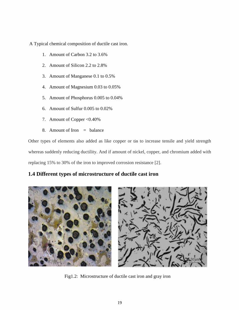
1.4 Different types of microstructure of ductile cast iron
Fig1.2: Microstructure of ductile cast iron and gray iron
20
Cast iron are the most used materials in engineering manufacturing. They belong to a family of
ferrous alloys. Application of cast iron have been based upon gray irons or flake graphite which
are providing an different range of tensile strengths between 150 N/mm² and 400N/mm² with
suggested design stresses in tensile applications of 0.25 x tensile strength. Different types of ductile
irons have tensile strengths ranging between from 350 to 1500 N/mm² with excellent elongation
and high toughness. Difference between ductile iron and grey iron is only the graphite formation
in the microstructure. Which is flake like or spherical nodules they form after proper treatments
and with the help of same alloying elements.
1.5: Ductile or brittle behavior of ductile cast iron
All ferrous materials, with the exception of the austenitic grades shows a transition from ductile to brittle
behavior when tested above and below a certain temperature known as transition temperature. A
comprehensive treatment of the subject by Barton has been used to identify and discuss some of the factors
affecting Ductile and Brittle behavior as follows. Ductile failure is accompanied by considerable general
or local plastic deformation, usually shown by visible distortion of a failed component and by slow crack
extension or tearing. A ductile fracture appears black in a fully ferritic ductile iron and gray in pearlitic
irons. Ductile fractures occur by tearing from the sites of graphite nodules along grain boundaries. So that,
the fracture contains numerous graphite nodules. Brittle failure, by contrast, generally occurs without
deformation, and very rapid crack propagation is involved. Brittle fractures in ductile irons are not
associated with graphite sites and occur by cleavage of the metallic grains, usually before
significant deformation has occurred. The separation through the grains very rapid and such
fractures appears bright because the cleavage facets of the grains reflect light, a brittle fracture
characteristically passes through the grains and very few, if any, graphite nodules are present along
the fracture path. The transition temperature of a material is raised if loading speeds are high or if
a notch is present. For this reason, brittle fractures are more commonly observed during impact

21
testing then there during normal tensile testing. It is important to appreciate, however, that brittle
failure can occur under normal tensile loading if the conditions favour this mode of failure. A
simplified explanation for this ductile – to – brittle transition behavior is shown in figure 1.7, At
higher temperatures, the stress required to cause plastic deformation is relatively low and failure
occurs in a ductile manner, with considerable deformation, before the stress to trigger brittle failure
by cleavage is exceeded. The stress required to cause plastic yielding increases rapidly as the
temperature is decreased, and the stress required to produce brittle fracture may then be exceeded
before plastic yielding can take place.
Fig 1.5: Ductile to Brittle transition occurs as temperature increases.
22
2. A BRIEF REVIEW OF PREVIOUS WORK ON DUCTILE CAST IRON
From the accessible writing and study materials, it is truly denoted that numerous endeavors were
made to comprehend and expect the practices of bendable iron that incorporates the investigation
of graphite morphology, its properties and its advancement, the change of grid structure by the
diverse warmth treatment, and we think about structure and properties relationship and its
mechanical properties and conceivable application [10]. A brief survey of a few literary works
here is introduced under here.
Literature Review
Ali M.Rashidi and M.Moshrefi-Torbati [5] have explored the impact of treating conditions on the
mechanical properties of ductile iron with double framework structure. Tempering is the most vital
heat treatment transform that was connected to extinguished steel & cast iron. The targets of this
procedure incorporate decreases the brittleness of the material, change of toughness and ductility
and decreases the cracking probability. The materials have that arrangement for dissected the
properties of test 3.56% C, 1.94% Si, 1.33%Ni, 0.28 %Mn, 0.29% Mo, 0.017%P, 0.012%S.
Keeping in mind locate a complete ferrite structure, the specimen were first heat treatment in
austenazing temperature at 950°C for 2 hrs. The examples were tempered at 300°C, 400°C, 450°C,
500°C, 600°C for 1 hrs furthermore at 500°C for 30, 90,120, 150 and 180 min. after heat treatment
diverse mechanical properties investigated. It was seen that by expanding the tempering
temperature, there was an ascent in elongation rate, past to the sudden rebound that happened
inside of the ranges of 400-500 °C, trailed by a moderate & progressive increment of elongation.
Consequently, if the point is to accomplish high ductility & toughness, the double stage pliable
iron with ferrite-martensite network structure ought to be tempered at temperature higher than
500°C.Again as the tempering temperature expanded, the yield quality extreme elasticity at first

23
reduced then inside of the scope of 400-500°C remained generally consistent and afterward there
was an ascent in extension rate for treating up to 120 min before it is at long last dropped. The
purpose behind this impoverishment was liable to be because of a phenomena called temper
embitterment. Inside of the temperature scope of 400-500°C, both quality and yield anxiety
diminish .Longer length of time of treating period at 500°C expands the extension rate for treating
period up to 120 min lessens quality and yield stress, from that point, they both go up once more.
For any mix of temperature of treating and treating period and of up to 120 min. the measure of
extreme rigidity can attractively be gotten from the expert bend's quality tempering parameter.

24
25

26
27

28
CHAPTER 3: 3.1 Properties of ductile cast iron.
Mechanical properties of ductile cast iron is very important. With the help of properties we know
about materials properties and its application. We consider that types of material to be used for
industrial applications which have perfect mechanical properties and with very economical.
During mechanical properties takes into account hardness, tensile strength, elongation, elastic
modulus, impact and fatigue strength, conductivity and machinability, physical properties include
damping capacity,. The material to be used should be capable to survive under the service
conditions without any risk. Which can be determined by its corrosion resistance wear resistance,
heat resistance.
Different types of mechanical properties of ductile cast iron:-
Tensile strength: Ductile iron has greater tensile strength mostly ranging between from 414Mpa
for ferritic grades of ductile iron and for martensitic or austempered ductile iron have 1380Mpa.
Yield strength: Yield strength is that stress at which the materials initiates to plastic deformation.
Ductile irons mostly have 0.2% yield strength. Yield strength of ferritic grades of ductile iron have
ranges from 275Mpa and martensitic grades of ductile iron have ranges from. 620Mpa
Ductility: Ductility is very important properties in cast iron. Austempered ductile irons have the
highest combination of strength and ductility properties. If the materials have more elongation
properties then it can’t break easily that types of materials have good strength and toughness.
Modulus of elasticity: Modulus of elasticity of ductile iron ranges from 162-170Gpa.
Ductile irons have a proportional stress-strain limit which is similar to the steels but is hampered
by plastic deformation.
Easy to cast: If materials have High fluidity then its enables to be easily casted.

29
Excellent corrosion resistance: Ductile irons have excellent corrosion resistance.
Machinability: Ductile iron have also excellent machinability due the presence of graphite which
is available in free form with softer phase. Therefor chip formation is easier in ductile iron.
Cost per unit strength: Ductile iron have very lower cost than other materials. Therefor its wide
range of applications in manufacture industry.
3.2 Effect of alloying elements on the mechanical properties.
1): Silicon: Adding of the Si in the ductile iron Melton metal which is provides the ferritic matrix
with pearlitic matrix. Silicon improves the properties of ductile iron at elevated temperature by
stabilizing. If increasing silicon content increase the proof stress, hardness and tensile strength.
Formation of ferritic matrix and silicon reach on surface layer, which is prevent the oxidation. The
potentially objectionable influences of increasing silicon content are:
1). Reduced impact test energy of materials.
2). Increased impact transition temperature of the materials.
3). Decreased thermal conductivity of materials.
Si is used to developed ferrite and to strengthen ferrite. Therefor Si is mostly held below 2.2%
when developing the ferritic grades and if producing pearlitic grades then Si content between 2.5%
and 2.8%.
2). Manganese: Manganese promote the mild pearlite, for developed required properties like proof
stress and hardness to a small level. Mn delays the beginning of the eutectoid transformation,
therefor its decreases the rate of diffusion of Carbon in ferrite and stabilize cementite (Fe3C)
formation. But due to embrittlement formation its limiting range between 0.3 to 1%.

30
3). copper: Copper is promoter strong pearlite formation. It increases the tensile Strength with
also proof stress and hardness with no embrittlement in matrix phase. Therefor for formation
pearlitic grade of the ductile Iron we used copper between ranges 0.4- 0.8% and is a contaminant
in the ferritic grade.
4). Nickel: Nickel help to increase the ultimate tensile strength without any affected of the impact
strength, therefor its added range between 0.5 to 2.0% in the metal composition to maintained the
proper and perfect mechanical properties. It has much less effect on strengthens ferrite, than
Silicon in reducing ductility. If nickel added more than 2% in materials than it is danger to
formation of embrittlement.
5). Molybdenum: Molybdenum is an also slight promoter the pearlite formation. In heavy
sections it Forms intercellular carbides. It Increases proof stress and hardness. There is also danger
of embrittlement, it is gives low tensile strength and ductility and also improves properties at
elevated temperature.
6). Chromium: chromium prevents the formation corrosion on the surface by forming of layer of
chromium oxide and it also prevent to exposition of the surface to atmosphere.it is not required
carbide free structure because it formed strong carbide.
8).Sulphur and Phosphorus: Amount of Phosphors in the metal kept very low, because It main
reasons for cold shortness therefor ductile iron properties will be ruined. But the S is better for
machinability, Sulphur amount kept very low between 0.009 to 0.015%. If larger amount of
Sulphur added it may cause the red shortness.
31
3.3 Applications of Ductile cast iron.
Ductile iron used in many industrial application to manufacture industrial equipment as like pipe
used for water and sewer lines. Its pipe are stronger and easier to tap and it requires very less
support and provides Better flow area for water. It also compared with others pipe which made
from other materials. Ductile iron pipe can be a Better choice than PVC, polyethylene, concrete,
or steel pipe. Ductile iron is very useful in automobile industry to made several automotive parts,
where strength needs better than of aluminum but do not necessarily require steel. The main
industrial applications of the ductile iron on off-highway diesel trucks, agricultural tractors, and
oil well pumps.
Engine crank shaft
Brake caliper, disc – brake anchor, brake anchor plate
Machine – tool bed
Electric insulator post and cap
Steering knuckle
Rack and pinion of steering assembly
Piston for impact drills
Rolling mill rolls
Moulding boxes and mould box clamps
Brake shoe for heavy duty brakes
Glass moulds
Spacer cage for rolling bearing
Piston rings
Wind mill items

32
CHAPTER 4. HEAT TREATMENT OF DUCTILE IRON
Heat treatment is a very valuable processes which can change the materials mechanical properties.
The heat Treatments can be done for formation of graphite and different types of microstructure.
Heat treatment is the control of microstructure and properties of materials, it allowing a high amount of
ferritic and pearlitic matrix in the materials microstructure. For better mechanical properties obtain by
improvement of heat treatment and different types of processes and if charge materials quality is better than
the application of consistent and effective practices for melting, inoculation holding, treating, and cooling
in the mold.
Following properties of ductile cast iron affected by heat treatment processes.
1. Increase toughness and ductility,
2. Increase strength and wear resistance,
3. Increase corrosion resistance,
4. Stabilize the Microstructure, to reduce growth,
5. Equalize properties in castings with widely varying section sizes,
6. Improve consistency of properties,
7. Improve machinability, and
8. Relieve internal stresses.
Different types of heat treatment processes:
1. Austenitizing
2. Tempering
3. Annealing
4. Normalizing
5. Quench Hardening
6. Austempering

33
4.1 Austenitizing
Austenitizing is a heat treatment process in which ferrous metal heat treated above the critical
temperature for an appropriately time that matrix of the materials fully transformed to austenite.
For produce a uniform matrix austenitizing temperature take before any heat treatment process.
The carbon content in the austenite phase is define by presence of silicon content at in the
austenitizing temperature. Time and Austenitizing temperature both are depend on the formation
of microstructure and composition of material. Austenitizing temperatures in the range (900-
950oC) are normally used in the heat treatment, with times ranging from 1h to 3h. If high amount
of silicon presence in the ductile iron then high nodule count, decrease breakdown times, carbide
stabilizers are presence as like chromium, vanadium and molybdenum required significantly more
times for nodule count. At lower temperatures pearlite decomposed rapidly than carbide
breakdown. This types of breakdown is improve by high amount of silicon and high nodularity
and underdeveloped by pearlite stabilizing elements such as copper, Manganese, tin, antimony,
and arsenic. Manganese and chromium both separated in to cell boundaries for incomplete
dissolution of both carbides and pearlite and to prevent mechanical properties to damage.
Figure 4.1: Conventional Quench & Tempering Process
34
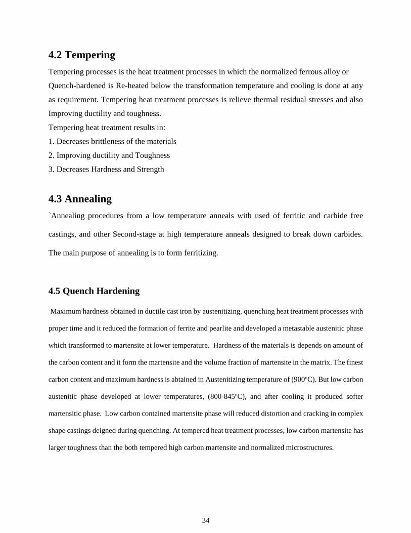
4.2 Tempering
Tempering processes is the heat treatment processes in which the normalized ferrous alloy or
Quench-hardened is Re-heated below the transformation temperature and cooling is done at any
as requirement. Tempering heat treatment processes is relieve thermal residual stresses and also
Improving ductility and toughness.
Tempering heat treatment results in:
1. Decreases brittleness of the materials
2. Improving ductility and Toughness
3. Decreases Hardness and Strength
4.3 Annealing
`Annealing procedures from a low temperature anneals with used of ferritic and carbide free
castings, and other Second-stage at high temperature anneals designed to break down carbides.
The main purpose of annealing is to form ferritizing.
4.5 Quench Hardening
Maximum hardness obtained in ductile cast iron by austenitizing, quenching heat treatment processes with
proper time and it reduced the formation of ferrite and pearlite and developed a metastable austenitic phase
which transformed to martensite at lower temperature. Hardness of the materials is depends on amount of
the carbon content and it form the martensite and the volume fraction of martensite in the matrix. The finest
carbon content and maximum hardness is abtained in Austenitizing temperature of (900oC). But low carbon
austenitic phase developed at lower temperatures, (800-845oC), and after cooling it produced softer
martensitic phase. Low carbon contained martensite phase will reduced distortion and cracking in complex
shape castings deigned during quenching. At tempered heat treatment processes, low carbon martensite has
larger toughness than the both tempered high carbon martensite and normalized microstructures.
35
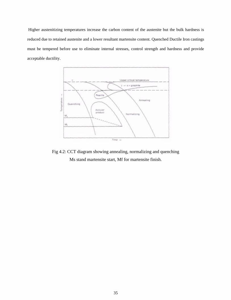
Higher austenitizing temperatures increase the carbon content of the austenite but the bulk hardness is
reduced due to retained austenite and a lower resultant martensite content. Quenched Ductile Iron castings
must be tempered before use to eliminate internal stresses, control strength and hardness and provide
acceptable ductility.
Fig 4.2: CCT diagram showing annealing, normalizing and quenching
Ms stand martensite start, Mf for martensite finish.

36
CHAPTER 5. EXPERIMENTAL PROCEDURE 5.1 Specimen preparation. Chemical compositions of the material are given in Table 5.1
Table 5.1 Chemical composition of specimens in wt. %
Elements Wt. %
C 3.52
Si 2.04
Mn 0.17
S 0.008
Mg 0.042
P 0.024
Cr 0.02
Ni 0.15
Mo 0.001
Cu 0.02
Ce 0.007
Fe Balance
I have 6 pieces of specimen, each have a specific size according to ASTM standards. The every
specimen have same gauge length but Width & thickness in measurement is according to fig.5.1.
Figure 5.1: Specimen Specifications
In order to investigate the structure-property relationship, ductile iron test blocks with different
alloying elements were brought from L&T Kansbahal, India. The chemical composition of test
block by weight percentage is presented in Table 5.1. In order to carry out the experiment
specimens were machined from the test blocks.

37
5.2 Heat treatment.
The various heat-treatments processes for our study were:
1. Austenitising
2. Quenching
3. Tempering
Austenitising
By using induction furnace for austempering process of all sample were heated in austeniging temperature
at 900°C for 120 minutes. After 120 minutes stop the furnace and quickly transferred the all sample in to
the salt bath or mineral oil at room temperature.
Quenching
All sample was quenched in mineral oil at room temperature up to 15 minutes. after quenching
Immediately tempering heat treatment processes was done of three sample at 400°C and remaining three at
200°C for different times 60 min, 90 min, and 120 min respectively.
Tempering
1) All the three sample tempered in the furnace and rise the temperature up to 400°C then
sample was kept on 400°C temperature up to 60 min, 90 min, and 120 min, respectively.
2) Then remaining all three sample again tempered in the furnace and rise the temperature up to 200°C
then sample was kept on 200°C temperature up to 60 min, 90 min, 120 min, respectively.
After heat treatment oxide layer from each of the specimen was removed by conventional filing & emery
paper polishing and cloth and diamond polishing method.

38
5.3 Tensile strength
Tensile test were carried out according to ASTM (E8 370-2002) Test were conducted by using
Instron 1195 universal testing machine connected to computer to draw the stress-strain curve
accounting to tensile strength, tensile load of 50KN applied to the specimen up to the breaking
point. Specimen have specific measurement of each sample. After failure we obtained tensile
strength of different sample and stress-strain curve at different time and temperature. After tensile
test we cut the small fracture surface part very carefully to investigate the brittle and ductile
behavior by using SEM (Scanning Electron Microscope).
Fractography: Fracture surface of the sample after tensile test are analyzed by scanning
Electron microscopy (SEM). First cleaned with acetone and properly handle, so that the fracture
surface does not get damaged. Thereafter the specimen is cut to appropriate size for analysis using
SEM (Scanning Electron Microscope.) Then all the specimens are kept under SEM for analysis
of fracture surface. A series of photographs are taken in due course of experiment which helps in
determining the type of fracture that has taken place.
5.4 Polishing & Etching.
After tensile test cut the small fracture surface and remaining part of sample use to investigate the
microstructure of materials by using grinding machine. Then all Specimens were first polished
with belt polisher then followed by 1/0, 2/0, 3/0, 4/0 grades of emery paper and given a sufficient
time for each paper and after paper polishing cloth polishing was done with using alumina slurry
followed and finally diamond polishing done. Then etched 2% nital. But after polishing takes
microstructure before etching for investigate the number of nodules and nodularity in each sample
then we takes 10 images of each sample and using Software to investigate the nodules and
nodularity.

39
5.5 Nodularity and Nodular count
Before etched taken metallographic images thought optical microscope and investigate number of
nodules present in the 1mm² area and calculate nodularity thought the computer software. We
takes 10 images of each sample before etching and by using metal power image analyzer software
we investigate the nodules and nodularity. Frist we select one image and select the circular shape
nodules and then remaining two phase and gives different color for each phase. Then similar
remaining all images and finally investigate the threshold value of all images and after we got the
number of nodules and nodularity as like given below.
Fig.5.2: Microstructure of sample 200°C at 1h before etching and threshold value of that image
Fig.5.3: Investigation report of sample 200°C at 1h by using metal power image analyzer software

40
Fig.5.4: Microstructure of sample 200°C at 1.5h before etching and threshold value of that image
Fig.5.5: Investigation report of sample 200°C at 1.5h by using metal power image analyzer
software
Fig.5.6: Microstructure of sample 200°C at 2h before etching and threshold value of that image

41
Fig.5.7: Investigation report of sample 200°C at 2h by using metal power image analyzer software
Fig.5.8: Microstructure of sample 400°C at 1h before etching and threshold value of that image
Fig.5.9: Investigation report of sample 400°C at 1h by using metal power image analyzer software
42
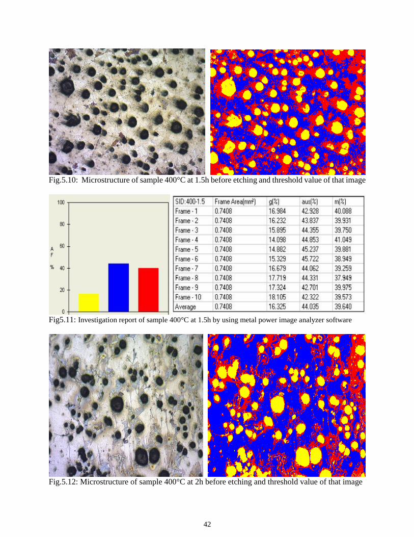
Fig.5.10: Microstructure of sample 400°C at 1.5h before etching and threshold value of that image
Fig5.11: Investigation report of sample 400°C at 1.5h by using metal power image analyzer software
Fig.5.12: Microstructure of sample 400°C at 2h before etching and threshold value of that image
43
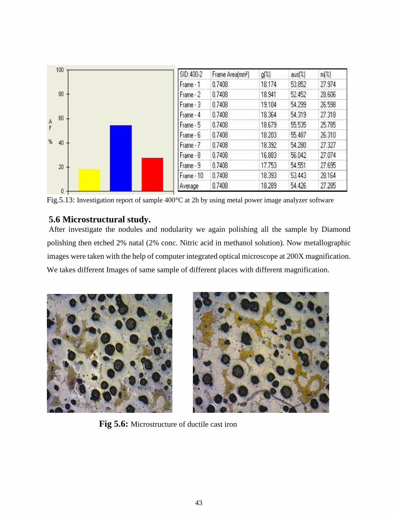
Fig.5.13: Investigation report of sample 400°C at 2h by using metal power image analyzer software
5.6 Microstructural study. After investigate the nodules and nodularity we again polishing all the sample by Diamond
polishing then etched 2% natal (2% conc. Nitric acid in methanol solution). Now metallographic
images were taken with the help of computer integrated optical microscope at 200X magnification.
We takes different Images of same sample of different places with different magnification.
Fig 5.6: Microstructure of ductile cast iron

44
5.7 STUDY OF MECHANICAL PROPERTIES:
5.7.1 Hardness testing
The method utilized for hardness testing was Vickers hardness testing. Vickers hardness was
measured by applying a load of 20Kg and dwell time being 10seconds on each heat treated
tempered specimen. When the load was applied by Instrument on the sample. The square shape
diamond indenter was penetrate the sample surface with in few 10 seconds. And by manually two
diagonals, d¹ and d², are measured. We measure 10 different place on same sample then take
averaged and the surface area calculated then divided into the load applied.
The method utilized for hardness testing was Vickers hardness testing (XHB20).
Fig.5.6.1: Measurement of hardness test by using Vickers hardness test

45
5.7.2 Impact testing:
Investigate the Impact energy by Charpy V-notch test and described in ASTM E23. The Charpy
specimen was placed horizontally across supports with the notch away from the hammer. The
indicator pointer was slide to the left until it indicates the maximum energy range on the upper
Charpy- Tension scale. The pendulum arm was raised to the right until it is firmly supported by
the latching mechanism. The pendulum was released by pushing up on the release knob. The
hammer dropped, striking the specimen, with a swing through dependent on the amount of energy
absorbed by the test specimen. The indicator moved and stopped when peak swing through was
registered, providing a direct reading of the energy absorbed by the specimen. The indicated value
from charpy scale was recorded.
Fig.5.7.1: Charpy V-Notch Impact Testing Specimen Measurements
Fig5.7.2: Charpy V-Notch Impact Testing Instrument

46
5.7.3 Wear test:
Wear properties investigate on Ducom TR-208-M1 Ball on plate type wear monitor. Specimen
was as flat plate and a spherical tipped diamond cone of 120° angle 4mm track diameter was used
in order to investigate the wear system response of the different tempered specimens. The
mechanism of Ball on plate wear test is very much similar to that of Pin on disc wear tester.
However the minor difference is that in pin-on-disc specimen is in the form of cylindrical pin, held
stationary in specimen holder and disc is the counter body which rotates against the pin, whereas
in case of Ball on plate wear test instead of pin specimen is a flat one rotates against a counter ball
which is fixed. Also, in pin on disc machine only the disc rotates whereas in Ball on plate
mechanism both the specimen and indenter rotate at same relative speed. The Ducom TR-208-M1
Ball on plate type wear monitor along with schematic diagram of pin on disc wear monitor is
presented in Fig. 1 (a) and Fig. 1 (b) respectively. Test was conducted at 20N loads for a sliding
distance of 7.54m at a constant speed 10rpm with three different wear time 10min, 20min, 30min,
respectively on each tempered sample. The weight loss for corresponding specimens was
measured with the help of electronic balance of 0.1mg accuracy. With the help of electronic data
plot graph to investigate the wear properties.
Fig.5.7.3: (b) Schematic diagram of pin on disc wear test machine
Fig.5.7.3 (a) Ducom TR-208-M1
Ball on plate type wear monitor

47
5.8:- Study of the X-Ray Diffraction:
The X-Ray diffraction (XRD) analysis was done for tempered samples. This method was used to
approximation the volume fractions of retained austenite, ferrite, martensite, of matrix in the
material after treatment. XRD was performed 40 KV and 40 mA using a Cu- Kα target
diffractometer. Scanning was done in angular range 2θ from 40° to 90° at a Scanning speed of
10°/min. The profile were analyzed on computer by using X’ Pert High Score and JCPDS Software
to obtain the peak position and integrated intensities of the {101}{2 0 0}{211} plane of BCC of
martensite at 200°C and other 400°C tempered sample obtained ferrite and {111},{220},{311}
planes of FCC austenite. By comparing these intensities the volume fractions of retained austenite
and ferrite were estimated.
48
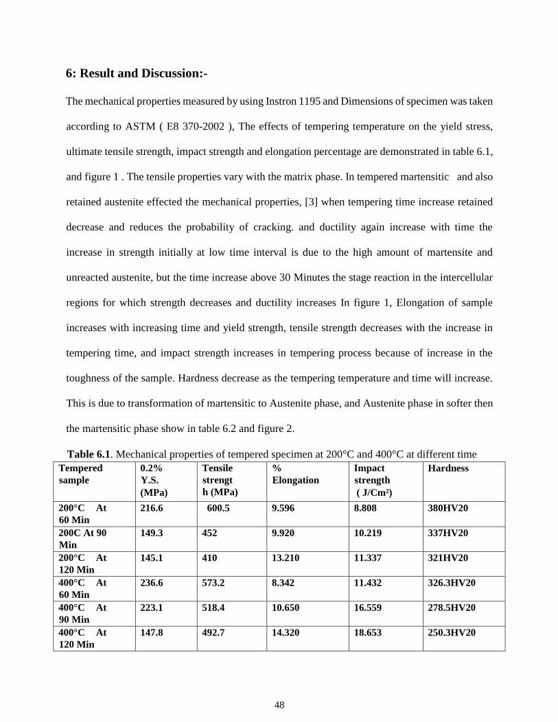
6: Result and Discussion:-
The mechanical properties measured by using Instron 1195 and Dimensions of specimen was taken
according to ASTM ( E8 370-2002 ), The effects of tempering temperature on the yield stress,
ultimate tensile strength, impact strength and elongation percentage are demonstrated in table 6.1,
and figure 1 . The tensile properties vary with the matrix phase. In tempered martensitic and also
retained austenite effected the mechanical properties, [3] when tempering time increase retained
decrease and reduces the probability of cracking. and ductility again increase with time the
increase in strength initially at low time interval is due to the high amount of martensite and
unreacted austenite, but the time increase above 30 Minutes the stage reaction in the intercellular
regions for which strength decreases and ductility increases In figure 1, Elongation of sample
increases with increasing time and yield strength, tensile strength decreases with the increase in
tempering time, and impact strength increases in tempering process because of increase in the
toughness of the sample. Hardness decrease as the tempering temperature and time will increase.
This is due to transformation of martensitic to Austenite phase, and Austenite phase in softer then
the martensitic phase show in table 6.2 and figure 2.
Table 6.1. Mechanical properties of tempered specimen at 200°C and 400°C at different time
Tempered
sample
0.2%
Y.S.
(MPa)
Tensile
strengt
h (MPa)
%
Elongation
Impact
strength
( J/Cm²)
Hardness
200°C At
60 Min
216.6 600.5 9.596 8.808 380HV20
200C At 90
Min
149.3 452 9.920 10.219 337HV20
200°C At
120 Min
145.1 410 13.210 11.337 321HV20
400°C At
60 Min
236.6 573.2 8.342 11.432 326.3HV20
400°C At
90 Min
223.1 518.4 10.650 16.559 278.5HV20
400°C At
120 Min
147.8 492.7 14.320 18.653 250.3HV20

49
[11]The drop in hardness accompanying secondary graphitization produces a corresponding
reduction in tensile and fatigue strength as well. [11] Because alloy content affects the rate of
secondary graphitization, each alloy will have a unique range of useful tempering temperatures.
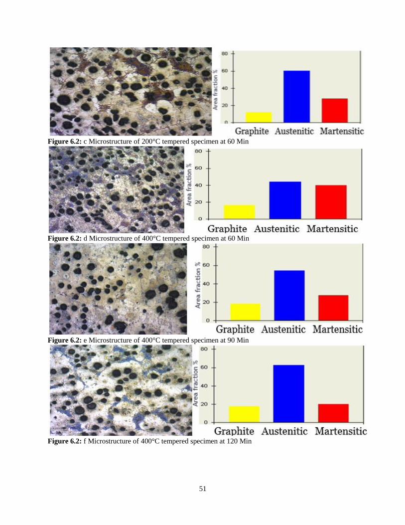
The microstructures of respective specimens were shown in Fig.2 and this microstructure have
different matrix phase, [10] tempered ductile Cast Iron have nodules graphite structure and they
have also austenite and martensitic phase. [12]. the nodularization amount and graphite shape have
a great effect on the workability
Figure.6.1: Effect of tempering Time On Elongation %, Impact Strength, Tensile Strength, Yield Strengt

50
In microstructures At 200°C have different amount of phase in table 3. at after austenitized temperature
sample immediately quench in mineral oil at room temperature then at quenching martensitic
transformation occurs and retained austenite formed ,after tempering in microstructures martensitic and
retained austenite will transform into austenite and austenite phase is softer than other, that amount of
matrix define the mechanical properties of ductile cast Iron.
Table 6.2. Amount of matrix presence in tempered specimen at different time and temperature
Figure 6.2:.a Microstructure of 200°C tempered specimen at 60 Min
Figure 6.2: b Microstructure of 200°C tempered specimen at 60 Min
Tempering
Temperature &Time
%of Martensitic %of Austenite % of Graphite Nodularity
200C at 60 Min 37.062% 45.029% 17.909% 79.630
200C at 90 Min 35.283% 45.861% 18.857% 100
200c at 120 Min 27.583% 60.473% 11.944% 79.167
400C at 60 Min 39.640% 44.035% 16.325% 96.327
400C at 90 Min 27.285% 54.426% 18.289% 100
400C at 120 Min 19.904% 62.342% 17.754% 87.143
51
Figure 6.2: c Microstructure of 200°C tempered specimen at 60 Min
Figure 6.2: d Microstructure of 400°C tempered specimen at 60 Min
Figure 6.2: e Microstructure of 400°C tempered specimen at 90 Min
Figure 6.2: f Microstructure of 400°C tempered specimen at 120 Min

52
The morphology of the fracture specimens are analyzed by Scanning Electron Microscopy (SEM).
Figure 3 show the fracture surface of different sample Specimens tempered at 200°C were
dominant by brittle failure mode characterized by the presence flat shiny surfaces. Whereas with
increase in tempering time shallow dimples were also observed in every specimens & were
increased in the specimen tempered for 120 minutes. On the other hand specimens tempered at
400°C for various times showed dimples around the spherical nodules suggesting dominating
nature of ductile failure mode. However the specimen tempered for 90 minutes showed mixed
mode of failure characterized by presence of flat shiny surfaces along with dimples. On the other
hand specimen tempered for 120 minutes showed complete ductile mode of failure.
(d) (e) (f)
Figure 6.3: Fractography Image of tempered specimen a) at 200°C in 60 min b) at 200°C in 90
min c) at 200°C in 120 min d) at 400°C in 60 min e) at 400°C in 90 min f) at 400°C in 120 min
a b c

53
Wear test:-
The tempered sample had the highest hardness value due to the hard martensite matrix. And when
tempering time increase then hardness decreased and so as the wear depth and weight loss. At
tempering temperature 400C in for 1.5hr the weight loss linear and for 1hr and 2hr weight loss
differ as different tempering time with wear time as given below in a figure7.4(b). And similar at
200C tempering sample shows differ as different tempering time with wear in figure 7.4(a).
10 15 20 25 30 35
0.01
0.02
0.03
0.04
0.05
0.06
0.07
0.08
0.09
% W
eig
th lo
ss
Time (min)
wear at (1hr)
wear at(1.5hr)
wear at (2hr)
10 15 20 25 30 35
0.01
0.02
0.03
0.04
0.05
0.06
0.07
0.08
0.09
0.10
0.11
% w
eig
ht lo
ss
Time (min)
wear at (1hr)
wear at(1.5hr)
wear at (2hr)
Fig.6.4: (a) % Weight Loss vs. time for Fig.6.4: (b) % Weight Loss vs. time for
Tempered sample at 200C tempered sample at 400C
Study of the wear mechanism:
To investigate the wear mechanism of micrographs of worn surfaces of heat treated Sample were
taken with the held, and presented in Fig.7.6. Direction of wear track was shown given below in
each case. It was found that for the sample tempered at 200°C for 1 hours the wear is mainly
caused by the delamination of the surface. At the minimum time duration of 10minutes samples
presents almost smooth surface with small delamination crater. When the time increases to 20

54
minutes, the worn surface shows rough surfaces with significant delamination damage. On further
increasing the time to 30 minutes, the wear surface shows intensively severe delamination damage
and more material pull out was observed. Similar observation was made in the sample tempered
at 200°C for 1.5hr and 2hr with increasing time duration. However at 200°C in 2hr at wear time
20 minutes and 30 minutes oxidation take place.
(a) (b) (c)
Fig.6.5: (A) image of wear surface at 200°C in 1hr at a) 10min b) 20 min c) 30min
(a) (b) (c)
Fig.6.5: (B) Fractography image of wear surface at 200°C in 1.5hr at a) 10min b)20 min c) 30min

55
(a) (b) (c)
Fig.6.5: (C) Fractography image of wear surface at 200°C in 2hr at a) 10min b) 20 min c) 30min
Fig.6.5: (D) EDX image of 200°Cat 2hr of 20min and 30min respectively.
(a) (b) (c)
Fig.6.5: (E) Fractography image of wear surface at 400°C in 1hr at a) 10min b) 20 min c)30min

56
(b) (b) (c)
Fig.6.5: (F ) Fractography image of wear surface at 400°C in 1.5hr at a)10min b)20 min c) 30min
(a) (b) (c)
Fig.6.5: (G) Fractography image of wear surface at 400°C in 2hr at a)10min b)20 min c) 30min
Fig.6.5: (H) EDX image of 400°C at 1hr of 30min respectively.
Element Weight% Atomic%
O K 19.50 43.75
Ca K 17.80 15.95
Fe K 62.70 40.31
Totals 100.00

57
Study of the X-ray diffraction:
The X-Ray diffraction pattern are shown in that figure 7.6, for different tempering temperature
and time. After analyzing diffraction peaks of respective sample it was found that sample tempered
at 200C have martensitic phase, (101) (200) (211), with retained austenaite (111) (200) (311).
Whereas sample tempered at 400C for varies time appeared to have martensite and ferretic phase.
40 60 80
Re
lative
in
ten
sity
2 theta
Ferrite
Martensite
a
b
c
Fig. 6.6: XRD analysis data of tempered sample with different matrix phases.
While, in tempered samples for 2 hours the amount of retained austenite is little higher than other
samples. The amount of retained austenite increases with time.

58
7. Conclusion
The result obtained from present work can be summarized in the following points.
1. By increase tempering time martensitic content reduced resulting in increase of ductility and reduction
of ultimate tensile strength and yield strength,
2. Within the temperature range of 200°C–400°C, there is a sudden increase in impact strength and
elongation percentage, whereas within the same temperature range, the ultimate tensile strength and yield
stress decreased.
3. Longer duration of tempering period at 200°C & 400°C increases the elongation percentage for tempering
periods up to 120 min, and ductility increases
4. Whereas with increase in tempering time light pits were also observed in every specimens & were
increased in the specimen tempered for 120 minutes. On the other hand specimens tempered at 400°C for
various time showed pits around the spherical nodules suggesting dominating nature of ductile failure mode
5. As the tempering temperature & time increases the impact energy increases, this means the energy
absorption capacity of Spheroidal graphite iron increases as the time & temperature of tempering increases.
6. The weight loss of specimens tempered at 400°C are higher than that of 200°C due to ferritic matrix and
increasing ductility with increased tempering temperature.
7. The major wear mechanism involved was observed to be adhesive type signified by presence of
delaminated layer. Tempering temperature and time was found to have very little effect on specimen
tempered at 200°C for 2hr under 30 minute dry sliding condition. It was observed that abrasive wear
mechanism was involved for this case.

59
8. Reference
[1] Siefer W.and Orths K., Transection AFS, volume 78, 1970, pages 382-387
[2] A guide to mechanical properties of ductile iron, Mid –Atlantic Casting Casting Service.
[3] Ductile Iron Society, http: www.ductile.org/ didata/Section3/3part1.htm
[4] Ali M. Rashidi, M.Moshrefi-torbati/Materials latters 45 (2000) 203-207, Mechanical
Engineering department, Razi University, Kermanshah, Iran
[5] Hughes ICH. Austempered ductile irons their properties and significance, Mater Des 6 (1985)
pp. 124
[6] AVNER Sidney H, Introduction to Physical Metallurgy, Second Edition, Chapter-11
[7] K. Okabayashi, M. Kawamoto, A. Ikenaga, M.Tsujikawa, Impact characteristics and
fractography of spheroidal graphite cast iron and graphite steel with hard eye structure, Trans.
Jpn. Foundrymen’s Soc.1982
[8] Anita bisht, effect of heat treatment prodedures on microstructure and mechanical properties of
nodular iron, metallurgical and materials engineering, Rourkela odisha, india, june-2009
[9] N. Wade, C. Lu, Y. Ueda, Effect of distribution of second phase on impact and tensile
properties of ductile cast iron with duplex matrix, Trans. Jpn. Foundrymen’s Soc Ž1985. 22–
26, April.
[10] M.Nili Ahmadabadi, H.M. Ghasemi, M.Osia, A.R. Ghaderi. Wear 255 (2003) 410–416
[11] Janina M. Radzikowska, Metallography and Microstructures of Cast Iron , The Foundry
Research Institute, Krako´w, Poland

60
[12] M.A.Shaker, A note on the effect of nodularization characteristion on the workability of
quench-hardened and tempered cast iron/ Journal of Materials Processing Technology, 32
(1992) 545-552, july-24-1991, faculty of engineering and technology suez canal university,
post said. Egypt
[13] A guide to mechanical properties of ductile iron, Mid- Atlantic Casting service.
[14] R.D.Forrest, J.D Mullins, “Achieving and maintaining optimum ductile iron metal Quality”,
Foundry, An Indian Journal for Progressive Metal-Casting, volume xv, no.4, July-August2003,
Pages51-58.
[15] Metal Handbook, Volume 9, chapter 6, Pages 70-90.
[16] Barton, R. “the selection of carbon and silicon contents in the production of as cast And heat
treated SG iron. Paper presented at: Proceeding of the Third International Conference of
I.O.scensees for the Converter Process Schaffhausen, Switzerland,7-10 October 1979, Paper-1
[17] Yan Mi. Scripta Metallurgical and Material, Volume32, 1995, Pages13-14.
[18] Study of the engineering properties of ductile, Technical report of ductile iron.
[19] Choi J.O, .Kim J.Y, Choi, C.O; Effect Of rare earth elements on microstructure Formation and
mechanical properties of thin walled ductile iron casting. Material
[20] Fatahalla. N., Bahi. S.; Metallurgical parameters, mechanical properties and machinability of
ductile cast iron, Journal of Materials Science 31 (1996) 5765 5772.
[21] Morrogh H., Influence of some residual elements & their neutralization in Magnesium treated
nodular cast iron. Source book of ductile iron.
[22] Hafiz M.; Mechanical properties of SG-iron with different matrix structure; journal of
Material Science, Volume 36, 2001, Pages 1293-1300.

61
[23] Stokes B., Gao N., Reed P.A.S.; Effects of graphite nodules on crack growth
Behaviour of austempered ductile iron; Materials Science and Engineering A; September
2006, Pages 374-385.
[24] Haseeb A.S.M.A., Islam Aminul et.al. Tribological behaviour of quenched and tempered, and
austempered ductile iron at the same hardness level; Journal of Wear, April, Pages 15-19.
[25] Mechanical Metallurgy; G.E.Dieter New York: McGraw-Hill Co.;
[26] Hafiz M.; Mechanical properties of SG-iron with different matrix structure;
Journal of Material Science, Volume 36, 2001, Pages 1293-1300.
[27] Introduction to Physical Metallurgy; Sidney H. Avenar.
[28] ASM, “Metals Handbook,” Vol. 15, 9th edition (American Society of Metals, Metal Park,
Ohio, USA,) 1992.
[29] A guide to mechanical properties of ductile iron, Mid- Atlantic Casting service.
[30] R.Kumar, R.behara, S.sen, Effect of tempering temperature and time on strength and hardness
of ductile cast iron, (doi:10.1088/1757-899X/75/1/012015)
[31] Karsay. “Production of S.G. iron”
[32]. Sidjanin L., Rajnovic D.; Characterization of Microstructure in Commercial Al-Si Piston
Alloy, Microscopy - advanced tools for tomorrow's materials - Autumn School on Materials
Science and Electron Microscopy 2007.
[33]. Wislei R. Osório, Noé Cheung, Leandro C. Peixoto and Amauri Garcia; Corrosion
Resistance and Mechanical Properties of an Al 9wt%Si Alloy Treated by Laser Surface
Remelting, Int. J. Electrochem. Sci., Vol. 4 (2009): pp. 820-831.
62
[34]. Torabian H., Pathak J.P. and Tiwai S.N.; Wear Characteristics of Al-Si alloys, Wear, Vol.
172 (1994), pp. 49-58.
[35]. Chen M., Alpas A.T.; Ultra-mild wear of a hypereutectic Al–18.5 wt. % Si alloy, Wear,
Vol. 265 (2008): pp. 186–195.
[36]. Goto H., Omori S. and Uchijo K.; Wear Behavior of Al-Si Alloy impregnated Graphite
Composite, Tribol. Trans., Vol. 44 (2001), 4, pp. 551-558.
[37]. E8M-03, Standard test method for tension testing of metallic materials (Metric), ASTM
Annual Book of Standards, 03.01, West Conshohocken, PA, 2003.
[38]. B.N. Pramila Bai and S.K. Biswas; Effect of magnesium addition and heat treatment on
mild wear of hypoeutectic aluminium-silicon alloys, Acta Metall. Mater., Vol. 39:5 (1991), pp.
833-840.
[39]. Basavakumar K.G., Mukunda P.G., Chakraborty M.; Dry sliding wear behaviour of Al–
12Si and Al–12Si–3Cu cast alloys, Mater. Des., Vol. 30 (2009), pp. 1258–1267.
Publication: Effect of tempering temperature and time on strength and hardness of ductile cast iron,
2015 IOP Conf. ser.: mater.sci.Eng. 75 012012
(htt://iopscience.iop.org/1757-899X/75/1/012015)
(doi:10.1088/1757-899X/75/1/012015)

63