Effect of Temperature on Carrying Capacity of Concrete ... Workbench. INTRODUCTION Reinforced...
13
Jordan Journal of Civil Engineering, Volume 14, No. 1, 2020 - 14 - © 2020 JUST. All Rights Reserved. Received on 18/11/2019. Accepted for Publication on 27/1/2020. Effect of Temperature on Carrying Capacity of Concrete Columns Confined with Multi-layers of CFRP Manar Takla 1) and Ihssan Tarsha 2) 1) PhD Student, Structural Engineering Department, Faculty of Civil Engineering, AL-Baath University, Syria. E-Mail: [email protected] 2) Professor, Structural Engineering Department, Faculty of Civil Engineering, AL-Wataniya Private University, Syria. E-Mail: [email protected] ABSTRACT FRP-reinforced polymers are widely accepted for use in civil engineering applications to strengthen constructions and apply confinement on concrete columns, thereby increasing their ductility and increasing their carrying capacity, as these materials are characterized by high tensile strength, high strength-to-weight ratio and high corrosion resistance,… etc. In addition, the exposure of reinforced concrete structures to fire is one of the most dangerous challenges that lead to great destruction and structural failure in addition to loss of life. With the development of computer simulation theories to study the behavior of elements and structures under the influence of different loads (static, dynamic, thermal,… etc.), it is possible to study the behavior of concrete columns under the influence of axial vertical and non-axial structural loads and compare the results with those of previous research, thus saving time, effort and cost instead of laboratory testing. Strengthening concrete columns with fiber-reinforced polymers (FRPs) has been studied extensively, but the majority of published studies have focused on circular columns. Most concrete columns in the field have square or rectangular cross-sections and resist eccentric loading as well. The objective of this study is to investigate the performance of square reinforced concrete (RC) columns, wrapped with carbon FRP subjected to elevated temperature; so, in this paper, an analytical study was conducted using the ANSYS Workbench program, which follows the finite element method, to determine the effect of layer number of CFRP on carrying capacity of concrete columns and to study the effect of external standard fire on concrete columns confined with CFRP. The numerical results were compared with experimental results as far as possible. The study revealed the accuracy of analytical models when compared to experimental studies. The results have shown that with increasing the layer number of CFRP, the carrying capacity of concrete columns will increase, with no benefit of increasing the number of CFRP layers to be more than 4, where polymer materials are sensitive to fire so that they need insulation. KEYWORDS: Confinement, CFRP, Concrete columns, External fire, Carrying capacity, ANSYS Workbench. INTRODUCTION Reinforced concrete is the most common material used in structural systems in the world. The behavior of these structures and their failure modes have been extensively studied. The use of fiber-reinforced polymer (FRP) composites that are externally applied for strengthening reinforced concrete structures, such as beams, slabs and columns, has been implemented experimentally by many researchers and has been
Transcript of Effect of Temperature on Carrying Capacity of Concrete ... Workbench. INTRODUCTION Reinforced...

Jordan Journal of Civil Engineering, Volume 14, No. 1, 2020
- 14 - © 2020 JUST. All Rights Reserved.
Received on 18/11/2019. Accepted for Publication on 27/1/2020.
Effect of Temperature on Carrying Capacity of Concrete Columns Confined
with Multi-layers of CFRP
Manar Takla1) and Ihssan Tarsha 2)
1) PhD Student, Structural Engineering Department, Faculty of Civil Engineering, AL-Baath University, Syria. E-Mail: [email protected]
2) Professor, Structural Engineering Department, Faculty of Civil Engineering, AL-Wataniya Private University, Syria. E-Mail: [email protected]
ABSTRACT
FRP-reinforced polymers are widely accepted for use in civil engineering applications to strengthen
constructions and apply confinement on concrete columns, thereby increasing their ductility and increasing
their carrying capacity, as these materials are characterized by high tensile strength, high strength-to-weight
ratio and high corrosion resistance,… etc. In addition, the exposure of reinforced concrete structures to fire is
one of the most dangerous challenges that lead to great destruction and structural failure in addition to loss of
life. With the development of computer simulation theories to study the behavior of elements and structures
under the influence of different loads (static, dynamic, thermal,… etc.), it is possible to study the behavior of
concrete columns under the influence of axial vertical and non-axial structural loads and compare the results
with those of previous research, thus saving time, effort and cost instead of laboratory testing. Strengthening
concrete columns with fiber-reinforced polymers (FRPs) has been studied extensively, but the majority of
published studies have focused on circular columns. Most concrete columns in the field have square or
rectangular cross-sections and resist eccentric loading as well. The objective of this study is to investigate the
performance of square reinforced concrete (RC) columns, wrapped with carbon FRP subjected to elevated
temperature; so, in this paper, an analytical study was conducted using the ANSYS Workbench program, which
follows the finite element method, to determine the effect of layer number of CFRP on carrying capacity of
concrete columns and to study the effect of external standard fire on concrete columns confined with CFRP.
The numerical results were compared with experimental results as far as possible. The study revealed the
accuracy of analytical models when compared to experimental studies. The results have shown that with
increasing the layer number of CFRP, the carrying capacity of concrete columns will increase, with no benefit
of increasing the number of CFRP layers to be more than 4, where polymer materials are sensitive to fire so
that they need insulation.
KEYWORDS: Confinement, CFRP, Concrete columns, External fire, Carrying capacity, ANSYS Workbench.
INTRODUCTION
Reinforced concrete is the most common material
used in structural systems in the world. The behavior of
these structures and their failure modes have been
extensively studied. The use of fiber-reinforced polymer
(FRP) composites that are externally applied for
strengthening reinforced concrete structures, such as
beams, slabs and columns, has been implemented
experimentally by many researchers and has been

Jordan Journal of Civil Engineering, Volume 14, No. 1, 2020
- 15 -
applied in construction. A column is one of the essential
elements in civil engineering structures that transmits
loads from the upper levels to the lower levels and then
to the soil through the foundations. During their service
life, columns confined by CFRP can undergo
deterioration caused by overloading, environmental
effects, as well as exposure to exterior deteriorating
factors, like fire, among other factors. Therefore, failure
of the column system in any structure for any reason
could lead to catastrophic effects on the entire building.
In addition, the degradation of concrete strength due to
short-term exposure to elevated temperature (fire) has
attracted the attention of researchers and practitioners in
the last decades, where the behavior of concrete exposed
to fire depends on its mix composition and is determined
by complex interactions during the heating process.
Modes of concrete failure under fire exposure vary
according to the nature of fire, loading system and type
of structure.
BACKGROUND
FRP systems were developed as alternatives to steel
plate bonding. Bonding steel plates to the tension zones
of concrete members with adhesive resins were shown
to be viable techniques for increasing flexural strength.
This technique has been used to strengthen many
bridges and high-rise buildings around the world.
Because steel plates can corrode, leading to
deterioration of the bond between steel and concrete and
because they are difficult to install, requiring the use of
heavy equipment, researchers have looked to FRP
materials as an alternative to steel. Experimental work
using FRP materials for retrofitting concrete structures
was reported as early as 1978 in Germany. Research in
Switzerland led to the first applications of externally
bonded FRP systems to reinforce concrete bridges for
flexural strengthening. FRP systems were first applied
to reinforced concrete columns for providing additional
confinement in Japan in the 1980s. Previous research
and field applications for FRP rehabilitation and
strengthening are described in ACI 440.2R-17 (2017).
In Europe, the International Federation for Structural
Concrete (FIB, 2001) published a bulletin for design
guidelines, entitled "externally bonded FRP
reinforcement for reinforced concrete structures”. In
recent years, research into FRP materials as
reinforcement for concrete has been steadily increasing
and a number of research gap analyses have been
reported which suggest that FRP behavior under fire is
a critical research need that must be addressed before
these materials will see widespread use in buildings. For
example, Karbhari et al. (2003) presented a durability
gap analysis for fiber-reinforced polymer composites in
civil infrastructures based on a series of workshops
conducted by the Civil Engineering Research
Foundation (CERF) and the Market Development
Alliance (MDA) in the United States. Gap analysis
provides a very instructive overview of the various
concerns associated with FRP under fire. Therefore, the
study of structural elements confined by carbon fiber
and exposed to fire is an important topic in the field of
civil engineering.
Model Generation
The ultimate purpose of finite element analysis is to
recreate numerically the behavior of an actual
engineering system. In other words, the analysis must
use an accurate numerical model of a physical prototype.
In the broadest sense, this model consists of the nodes,
elements, material properties, real constants, boundary
conditions and other features that are used to represent
the physical system.
Structural Elements (Tarsha and Takla, 2017;
ANSYS, 2015; SAS ANSYS, 2008)
Solid65 Element Description
SOLID65 is used for the 3-D modeling of solids with
or without reinforcing bars (rebar). The SOLID65 is
capable of cracking in tension and crushing in
compression. In concrete applications, for example, the
SOLID65 capability of the element may be used to
model the concrete, while the rebar capability is

Effect of Temperature on… Manar Takla and Ihssan Tarsha
- 16 -
available for modeling reinforcement behavior. The
element is defined by eight nodes having three degrees
of freedom at each node: translations in the nodal x, y
and z directions. Up to three different rebar
specifications may be defined. The concrete element is
similar to a 3-D structural solid, but with the addition of
special cracking and crushing capabilities. The most
important aspect of this element is the treatment of
nonlinear material properties. The concrete is capable of
cracking (in three orthogonal directions), crushing,
plastic deformation and creep. Rebars are capable of
tension and compression, but not shear. They are also
capable of plastic deformation and creep.
The geometry, node locations and the coordinate
system for this element are shown in Figure 1.
Figure (1): SOLID65 geometry
Link180 Element Description
ANSYS presents element LINK180 to accurately
model reinforcing steel. LINK180 is a spar element that can
be used in a variety of engineering applications. This
element can be used to model trusses, sagging cables, links,
springs, … etc. This 3-D spar element is a uniaxial tension-
compression element with three degrees of freedom at each
node: translations in the nodal x, y and z directions. As in a
pin-jointed structure, no bending of the element is
considered. Plasticity, creep, rotation, large deflection and
large strain capabilities are included. The element is not
capable of carrying bending loads. The stress is assumed to
be uniform over the entire element. The geometry, node
location and the coordinate system for this element are
shown in Figure 2.
v Figure (2): LINK180 geometry
Solid180 Element Description
This element could be used for 3-D modeling of
solid structures. It is defined by eight nodes having three
degrees of freedom at each node: translations in the
nodal x, y and z directions. The geometry, node location
and the coordinate system for this element are shown in
Figure 3.
Figure (3): Solid180 geometry
Thermal Elements
Solid 70 Element Description
This element has a 3-D thermal conduction
capability. The element has eight nodes with a single
degree of freedom, temperature, at each node. The
element is applicable to a 3-D, steady-state or transient
thermal analysis. If the model containing the conducting
solid element is also to be structurally analyzed, the
element should be replaced by an equivalent structural
element. This 8-node brick element is used, in this study,
to simulate the behavior of concrete at thermal analysis.
The geometry, node location and the coordinate system
for this element are shown in Figure 4.

Jordan Journal of Civil Engineering, Volume 14, No. 1, 2020
- 17 -
Figure (4): Solid70 geometry
Link 33 Element Description
This element is a uniaxial element with the ability to
conduct heat between its nodes. The element has a single
degree of freedom, temperature, at each node point. The
conducting bar is applicable to a steady-state or transient
thermal analysis. If the model containing the conducting
bar element is also to be structurally analyzed, the bar
element should be replaced by an equivalent structural
element. This element is used, in this study, to simulate
the behavior of steel reinforcement. The geometry, node
location and the coordinate system for this element are
shown in Figure 5.
Figure (5): Link33 geometry
Structural and Thermal Analysis
The experimental model OCO (Hadi, 2012) was
used to define the analysis parameters and compare
experimental and analytical results. Material properties,
model properties and thermal material properties are
shown in Tables 1, 2 and 3, respectively.
Table 1. Material properties
Material Properties Element Type Material Number
Linear Isotropic
Solid65
1
47925 MPa Young’s modulus
0.2 Poisson’s ratio
Multilinear Isotropic
Stress (MPa) Strain
23.50 0.000497 Point1
37.28 0.0009 Point2
52.93 0.0014 Point3
60.59 0.0017 Point4
66.96 0.002 Point5
73.42 0.0024 Point6
75.78 0.0026 Point7
77.56 0.0028 Point8
78.77 0.003 Point9
79.5 0.00332 Point10
Concrete
0.3 Open shear transfer coef.
0.8 Closed shear transfer coef.

Effect of Temperature on… Manar Takla and Ihssan Tarsha
- 18 -
7.95 Uniaxial cracking stress
-1 Uniaxial crushing stress
0 Biaxial crushing stress
0 Hydrostatic pressure
0 Hydro biax crushing stress
0 Hydro uniax crushing stress
0.6 Tensile crack factor
Linear Isotropic(S)
Link180
2
2.1e5 MPa Young’s modulus
0.3 Poisson’s ratio
Bilinear Isotropic(S)
516 MPa Yield stress
2100 MPa Tangent modulus
Linear Isotropic (L)
2.1e5 MPa Young’s modulus
0.3 Poisson’s ratio
Bilinear Isotropic (L)
564 MPa Yield stress
2100 MPa Tangent modulus
Linear Isotropic Solid185 3
2.1e5 MPa Young’s modulus
Table2. Model properties
Model properties
200 200 800 Cross-section (mm)
79.5 Compressive strength of concrete
20 Concrete cover (mm)
564 Yield strength of longitudinal steel reinforcement
(MPa)
516 Yield strength of transverse steel reinforcement
(MPa)
12 Diameter of longitudinal steel reinforcement (mm)
8 Diameter of transverse steel reinforcement (mm)

Jordan Journal of Civil Engineering, Volume 14, No. 1, 2020
- 19 -
Table 3. Thermal material properties
Material properties for elements used in thermal analysis
Value Property Element Number
2300 Density [kg/m3]
Solid70 1 1100 Specific heat [J]/ [kg].[K] 1.2 Conductivity [W]/[m].[K]
1e-5 Thermal expansion
7850 Density [kg/m3]
Link33 2 700 Specific heat [J]/ [kg].[K] 45 Conductivity [W]/[m].[K]
1.3e-5 Thermal expansion
Results of Structural Analysis
The results of the analysis gave great accuracy after
the completion of the numerical analysis of the reference
model OCO (Hadi, 2012), where the ratio of the
difference between failure loads determined analytically
and experimentally was as follows:
- 0.9% for unconfined model. - 0.73 % for columns with one layer of CFRP.
- 3.24 % for columns with three layers of CFRP.
Therefore, it can be considered that the analytical
model agrees with the experimental model.
The results of structural analysis are included in
Table 4 and Figures 6, 7, 8, 9, 10 and 11, respectively.
Figure 12 shows the relationship between the number of
carbon fiber layers and the carrying capacity of the
columns. The compressive strength of the confined
concrete results obtained from the analysis are shown in
Table 5. As for Figure 13, it shows the relationship of
the numbers of carbon fiber layers with the compressive
strength of confined concrete (𝑓CC).
Table 4. Numerical results as obtained by ANSYS Workbench
Failure load (kN)
Model Analytical
Experimental
(Hadi, 2012)
3160.7 ----- C79.5-L12
3218.7 3248 C79.5-L12-S8
3255 3279 C79.5-L12-S8+1CFRP
3306.9 ----- C79.5-L12-S8+2CFRP
3468.7 3585 C79.5-L12-S8+3CFRP
3479.7 ------ C79.5-L12-S8+4CFRP
C-concrete; L-longitudinal reinforcement; S-stirrups’ reinforcement

Effect of Temperature on… Manar Takla and Ihssan Tarsha
- 20 -

Jordan Journal of Civil Engineering, Volume 14, No. 1, 2020
- 21 -
Figure (12): The relationship between the number of carbon fiber layers and
the carrying capacity of columns
Table 5. Compressive strength of the confined concrete
The numerical results by ANSYS Workbench
Compressive strength of the
confined concrete 𝒇𝒄𝒄 𝑴𝑷𝒂 Failure load (kN) Model
82.06 3160.7 C79.5-L12
3218.7 C79.5-L12-S8
83.66 3255 C79.5-L12-S8+1CFRP
85.95 3306.9 C79.5-L12-S8+2CFRP
93.09 3468.7 C79.5-L12-S8+3CFRP
93.58 3479.7 C79.5-L12-S8+4CFRP
The compressive strength of the confined concrete
was calculated as follows:
(1)
where:
where: 𝑁 : Failure load (kN).
f : Compressive strength of the concrete.
f : Compressive strength of the confined concrete.
A : Area of the concrete within the center lines of the
perimeter hoop.
(2)
3218.73255
3306.9
3468.7 3479.7
3050
3100
3150
3200
3250
3300
3350
3400
3450
3500
0 1 2 3 4
carr
yin
g c
apac
ity
of
colu
mn
s (K
N)
Number of carbon fiber layers

Effect of Temperature on… Manar Takla and Ihssan Tarsha
- 22 -
Figure (13): The relationship between the number of carbon fiber layers and compressive strength of confined concrete (𝑓CC)
Thermal Structure Analysis (Tarsha and Takla,
2016; Tarsha and Takla, 2019; SAS ANSYS, 2008)
The analysis consists of two parts: thermal analysis to
evaluate the fire temperature distribution inside the
columns and structural analysis to evaluate its structural
response, see Figure 14. The analysis was performed by
using ANSYS Workbench computer program. The
models were exposed to external fire from 4 sides. The
equation of fire is given as:
.20).313.0.687.01(.660 8.332.0 ttg eeT
Thermal distribution at 60 minutes of model C79.5-L12-
S8 is shown in Figure 15. As for Table 6 and Figure 16,
they show the numerical results as obtained by ANSYS
Workbench after thermal structure analysis.
Figure (14): Analysis methodology
82.06
83.66
85.95
93.0993.58
79.5
81.5
83.5
85.5
87.5
89.5
91.5
93.5
0 1 2 3 4
com
pre
ssiv
e st
ren
gth
of
con
fin
ed c
on
cret
e (M
Pa)
Number of carbon fiber layers
Jordan Journal of Civil Engineering, Volume 14, No. 1, 2020
- 23 -
Figure (15): Thermal distribution at 60 minutes of model C79.5-L12-S8
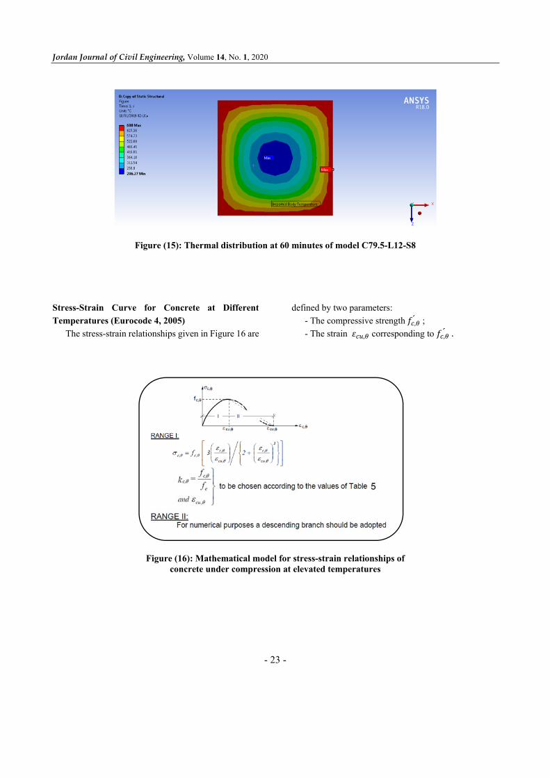
Stress-Strain Curve for Concrete at Different
Temperatures (Eurocode 4, 2005)
The stress-strain relationships given in Figure 16 are
defined by two parameters:
- The compressive strength 𝑓 , ; - The strain 𝜀 , corresponding to 𝑓 , .
Figure (16): Mathematical model for stress-strain relationships of concrete under compression at elevated temperatures

Effect of Temperature on… Manar Takla and Ihssan Tarsha
- 24 -
Table 6. Values for the two main parameters of the stress-strain relationships of normal weight concrete (NC)
and lightweight concrete (LC) at elevated temperatures
𝛆𝐜𝐮,𝛉 𝟏𝟎 𝟑 NC
𝑲𝒄,𝜽 𝒇𝒄,𝜽 /𝒇𝒄´ Concrete Temperature
𝜽𝒄 [ºC] LC NC
2.5 1 1 20 4 1 1 100
5.5 1 0.95 200 7 1 0.85 300
10 0.88 0.75 400 15 0.76 0.6 500 25 0.64 0.45 600 25 0.52 0.3 700 25 0.4 0.15 800 25 0.28 0.08 900 25 0.16 0.04 1000 25 0.04 0.01 1100
- 0 0 1200
Figure (17): Stress-strain curves for concrete at different temperatures used in the program
0
10
20
30
40
50
60
70
80
0 0.005 0.01 0.015 0.02 0.025
Str
ess
(MP
a)
Strain
20 ℃ 100 ℃ 200 ℃ 300 ℃ 400 ℃
500 ℃ 600 ℃ 700 ℃ 800 ℃ 900 ℃
Jordan Journal of Civil Engineering, Volume 14, No. 1, 2020
- 25 -
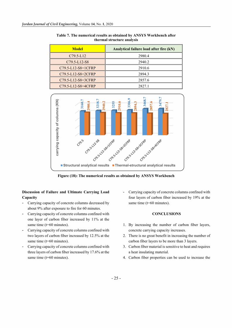
Table 7. The numerical results as obtained by ANSYS Workbench after thermal structure analysis
Model Analytical failure load after fire (kN)
C79.5-L12 2980.4 C79.5-L12-S8 2940.2
C79.5-L12-S8+1CFRP 2910.6
C79.5-L12-S8+2CFRP 2894.3
C79.5-L12-S8+3CFRP 2857.6
C79.5-L12-S8+4CFRP 2827.1
Figure (18): The numerical results as obtained by ANSYS Workbench
Discussion of Failure and Ultimate Carrying Load
Capacity
- Carrying capacity of concrete columns decreased by
about 9% after exposure to fire for 60 minutes.
- Carrying capacity of concrete columns confined with
one layer of carbon fiber increased by 11% at the
same time (t=60 minutes).
- Carrying capacity of concrete columns confined with
two layers of carbon fiber increased by 12.5% at the
same time (t=60 minutes).
- Carrying capacity of concrete columns confined with
three layers of carbon fiber increased by 17.6% at the
same time (t=60 minutes).
- Carrying capacity of concrete columns confined with
four layers of carbon fiber increased by 19% at the
same time (t=60 minutes).
CONCLUSIONS
1. By increasing the number of carbon fiber layers,
concrete carrying capacity increases.
2. There is no great benefit in increasing the number of
carbon fiber layers to be more than 3 layers.
3. Carbon fiber material is sensitive to heat and requires
a heat insulating material.
4. Carbon fiber properties can be used to increase the
3160
.7
3218
.7
3255
3306
.9
3468
.7
3479
.7
2980
.4
2940
.2
2910
.6
2894
.3
2857
.6
2827
.1
carr
yin
g c
apac
ity
of
colu
mn
s (K
N)
Structural analytical results Thermal-structural analytical results
Effect of Temperature on… Manar Takla and Ihssan Tarsha
- 26 -
carrying capacity of concrete columns only if these
fibers are protected from heat by insulating materials
or by using thermal treatment fibers.
Recommendations
1. Conducting experimental studies and comparing the
results of this research with the experimental results.
2. Using carbon fiber insulation materials when
exposed to fire and investigating the effectiveness of
these materials.
Acknowledgments
The authors would like to express their thanks and
appreciation to Al Baath and Yarmouk Universities for
supporting this research.
REFERENCES
ACI 318M-08. (2008). “Building code requirements for
structural concrete and commentary”.
ACI 440. 2R-17. (2017). "Guide for the design and
construction of externally bonded FRP systems for
strengthening concrete structures”.
ACI Committee 440. (2008). “Guide for the design and
construction of externally bonded FRP systems for
strengthening concrete structures; ACI 440.2R-08”.
American Concrete Institute: Farmington Hills, MI,
USA.
ANSYS. (2015). “Manuals”.
Eurocode 4. (2005). “Design of composite steel and
concrete structures, part 1-2: General rules-structural
fire design.
FIB. (2001). “Externally bonded FRP reinforcement for RC
structures”. FIB, Lausanne, 138.
Hadi, M.W. (2012). "Axial and flexural performance of
square RC columns wrapped with CFRP under eccentric
loading". Journal of Composites for Construction, 16
(6), 640-649.
Ihsan Tarsha, and Manar Takla. (2017). “Effect of fire on
confined concrete columns under axial loading”. IISTE:
International Knowledge Sharing Platform, 9 (9).
Ihssan Tarsha, and Manar Takla. (2016). “Ultimate load for
composite column subjected to ISO 834 fire”. Journal of
Al- Baath University, 38.
Ihssan Tarsha, and Manar Takla. (2019). Determination of
failure load for structural elements exposed to fire and
comparison to the design load according to Isotherm500
method”. Journal of Al Baath University, 41.
KarbharI, V.M., Chin, J.W., Hunston, D., Benmokrane, B.,
Juska, T., Morgan, R., Lesko, J.J., Sorathia, U., and
Reynaud, D. (2003). “Durability gap analysis for fiber-
reinforced composites in civil infrastructure”. Journal of
Composites for Construction, 7 (3), 238-247.
SAS ANSYS 12. (2008). “Finite element analysis system".
SAS IP, Inc, USA.