
Effect of Surfactants on the Rheological Properties and ...
69
CLASSIFIED DOCUMENT. USE ONLY FOR EVALUATION PURPOSES Master in Chemical Engineering Effect of Surfactants on the Rheological Properties and Microstructure of MWCNT/Epoxy Resin Suspensions A Master’s Dissertation of Carolina Sá da Cruz Developed within the course of dissertation held in INEGI – Instituto de Ciência e Inovação em Engenharia Mecânica e Engenharia Industrial Supervisor at FEUP: Dr. Ricardo Santos Supervisor at INEGI: Dra. Marina Torres Departamento de Engenharia Química July of 2017
Transcript of Effect of Surfactants on the Rheological Properties and ...

CLASSIFIED DOCUMENT. USE ONLY FOR EVALUATION PURPOSES
Master in Chemical Engineering
Effect of Surfactants on the Rheological Properties and Microstructure of MWCNT/Epoxy
Resin Suspensions
A Master’s Dissertation
of
Carolina Sá da Cruz
Developed within the course of dissertation
held in
INEGI – Instituto de Ciência e Inovação em Engenharia Mecânica e Engenharia
Industrial
Supervisor at FEUP: Dr. Ricardo Santos
Supervisor at INEGI: Dra. Marina Torres
Departamento de Engenharia Química
July of 2017


Effect of Surfactants on the Rheological Properties and Microstructure of MWCNT/Epoxy Resin Suspensions
Acknowledgement
This thesis had important support elements, which without it would be not possible to do this project.
First, I would like to express my great gratitude to INEGI, particularly the UMEC group and
Dr. Nuno Rocha, for the opportunity to develop this work and for all the support.
Additionally, I would like to acknowledge the project PTDC/CTM-POL/4607/2014 - High performance
multifunctional composite materials based on self-assembly approaches; project NORTE-01-0145-FEDER-
000022 – SciTech - Science and Technology for Competitive and Sustainable Industries; and project H2020
Grant Agreement No 685844 - ModComp – Modified cost effective fiber based structures with improved
multi-functionality and performance.
I would like to thank Dra. Marina Torres for providing her knowledge and time in the preparation and
development of this thesis, as well as for all the autonomy that allowed the development of my abilities .
Additionally, I would like to thank Dr. Ricardo Santos for his supervising, useful discussions and critical
review relative to this project.
Also, acknowledgement and thanks are extended to Dra. Raquel Santos and Jéssica Rocha for providing
their time and moral support throughout this work, and for assisting me in the activities entrusted to
me.
To Magda for her friendship, motivation and company throughout this semester and for our memorial
conversations that I will keep forever. Also, to ‘Almoçaradas’ group for the funny moments that we spend
and the conversations that we share.
And, at last, a special thanks to my parents for their support in all the stages of my life and especially
to my brother for his precious advices.


Effect of Surfactants on the Rheological Properties and Microstructure of MWCNT/Epoxy Resin Suspensions
Resumo
O objetivo da presente tese visa o estudo do efeito de nanotubos de carbono e de métodos de
funcionalização não-covalentes no comportamento reológico de suspensões de res ina epóxi/nanotubos
de carbono. A técnica de funcionalização não covalente utilizada envolveu o uso de surfactantes, de
forma a promover uma melhor dispersão das cargas na matriz polimérica. Os resultados reológicos foram
posteriormente correlacionados com a microestrutura das amostras, através da realização de análises de
microscopia ótica e testes de condutividade elétrica.
A caracterização reológica das suspensões, envolveu a realização de testes de fluxo, com variação da
taxa de corte, e oscilatórios, com variação da frequência angular. Os dados reológicos de cada amostra
permitiram a determinação de parâmetros reológicos específicos de cada mistura, nomeadamente a
tensão de cedência, o índice tixotrópico e a frequência angular crítica. Os resultados obtidos mostram
um aumento da viscosidade das suspensões com o aumento da concentração de nanotubos. A percolação
reológica ocorreu entre 0.25 % (m/m) e 0.375 % (m/m) de nanotubos, sendo a rede física mais rígida e
estável com o aumento do conteúdo de cargas. Assim, o aumento da rigidez da rede pressupôs o aumento
da tensão de cedência e do índice tixotrópico. Misturas contendo 1.0 % (m/m) de nanotubos foram
selecionadas para testes posteriores, de modo a garantir a existência de uma rede estável e
completamente formada. Para promover uma melhor dispersão das cargas, foram testados três
surfactantes com diferentes polaridades e pesos moleculares (Triton X-100, SDBS e PPGMBE) e
adicionados a misturas com 1.0 % (m/m) de nanotubos. Os resultados não mostram uma variação
significativa da viscosidade das suspensões em relação à amostra sem surfactante. No entanto, devido
ao efeito plastificante, a microestrutura dos materiais foi afetada, tendo levado a uma diminuição da
tensão de cedência e do índice tixotrópico.
A dispersão das amostras foi igualmente estudada para complementar os resultados obtidos e verificar o
desempenho dos surfactantes. Os dados revelaram que o aumento da concentração de nanotubos não
provocou o aumento do número de aglomerados, contudo provocou o aumento da área dos mesmos. A
utilização dos surfactantes revelou a melhoria da dispersão, tendo o Triton X-100 desempenhado uma
melhor performance, comparativamente ao SDBS. A caracterização elétrica dos nanocompósitos também
foi efetuada, tendo-se constatado que a percolação elétrica ocorreu antes da percolação reológica
(< 0.125 % (m/m) de nanotubos). Além disso, as amostras funcionalizadas demonstraram maior
condutividade elétrica para baixas concentrações de surfactante, embora para concentrações mais
elevadas a condutividade tenha diminuído. Este efeito estará associado à separação excessiva das cargas
por parte dos dispersantes, que impede o contacto direto entre estas , e provocando o aumento da
resistência elétrica.
Palavras Chave: Nanocompósitos; Nanotubos de Carbono; Reologia; Propriedades
reológicas; Dispersão; Propriedades elétricas

Effect of Surfactants on the Rheological Properties and Microstructure of MWCNT/Epoxy Resin Suspensions
Abstract
The objective of the present thesis aim the study of the effect of untreated carbon nanotubes (CNTs)
and non-covalent functionalization methods on the rheological behavior of epoxy/multi-wall carbon
nanotubes (MWCNTs) suspensions. The non-covalent functionalization technique employed on the work
was the use of surfactants, to promote a better dispersion of the fillers into epoxy polymeric matrix. The
rheological results were correlated with the microstructure of the samples, which was analyzed through
optical microscopy and electrical conductivity tests.
The rheological characterization of the suspensions, carried out in a rheometer, involved the
performance of flow and oscillatory frequency experiments. The rheological data of each sample was
analyzed and specific rheological parameters of each mixture were determined, namely yield stress,
thixotropic index and critical angular frequency. The obtained data show an increase in the viscosity
suspensions with the increasing of MWCNT content. The rheological percolation threshold occurred
between 0.25 % (m/m) and 0.375 % (m/m) of MWCNTs, being the physical network more rigid and stable
with the further increase of fillers content. Thus, the increase of network’s strength presupposed an
increase in rheological parameters (yield stress and thixotropic index). The amount of 1.0 % (m/m) of
CNT was chosen for further tests, because it was considered that the fully developed network was formed
at this point.
To promote a better dispersion of the CNTs, three surfactants with different polarities and molecular
weights (Triton X-100, SDBS and PPGMBE) were added to mixtures with 1.0 % (m/m) of MWCNT. The
results do not show a significant variation of the suspensions viscosity in relation to the sample without
surfactant. However, a decrease in yield stress and thixotropic index was obtained, which suggested that
the microstructure of the samples was affected by the presence of the surfactants, due to their
plasticizer effect.
The dispersion degree of samples was studied to complement the results obtained and to verify the
performance of the surfactants. The data revealed that with an increase in the CNT amount, the number
of aggregates maintained similar, but the aggregates area increased. The addition of surfactants revealed
to be beneficent for the dispersion of fillers, with best performance of Triton X-100 in comparison with
SDBS, allowing the reduction of agglomerates size and number, in relation with the sample without
functionalization.
At last, electrical characterization on nanocomposites was also performed, having obtained an electrical
percolation threshold lower than the rheological percolation (< 0.125 % (m/m) MWCNT). The
functionalized samples demonstrated higher electrical conductivity, although at higher surfactant
concentration the value decline due to the excessive separation of the fillers.
Keywords: Nanocomposites; Carbon nanotubes; Rheology; Rheological
properties; Dispersion; Electrical properties


Effect of Surfactants on the Rheological Properties and Microstructure of MWCNT/Epoxy Resin Suspensions
Declaration
I hereby declare, on my word of honour, that this work is original and that all
non-original contributions were properly referenced with source identification.
Porto, ___ July 2017
______________________________________


Effect of Surfactants on the Rheological Properties and Microstructure of MWCNT/Epoxy Resin Suspensions
i
Table of Contents
1 Introduction ................................................................................................................................ 1
1.1 Presentation of the Work .........................................................................................................1
1.2 Company Presentation.............................................................................................................2
1.3 Contributions of the Work........................................................................................................2
1.4 Organization of the Thesis .......................................................................................................3
2 Context and State of Art ............................................................................................................... 5
2.1 Nanotechnology......................................................................................................................5
2.2 Composite Materials ...............................................................................................................5
2.2.1 Carbon Fiber Reinforced Polymers (CFRP) ................................................................................6
2.2.2 Carbon Nanofiller Composite Materials ....................................................................................7
2.2.3 Processing of Carbon Nanotube-Polymer Composite Materials......................................................8
2.3 Surfactants............................................................................................................................9
2.3.1 Dispersing Carbon Nanotubes using Surfactants ....................................................................... 10
2.4 Rheology ............................................................................................................................. 11
2.5 Materials Behavior ................................................................................................................ 11
2.5.1 Ideal Elastic Behavior......................................................................................................... 11
2.5.2 Ideal Viscous Behavior ........................................................................................................ 12
2.5.3 Newtonian and Non-Newtonian Behavior................................................................................ 12
2.5.4 Viscoelastic Behavior ......................................................................................................... 12
2.5.5 Linear Viscoelasticity ......................................................................................................... 13
2.6 Aspects of Rheometry............................................................................................................ 13
2.6.1 Methods of Measuring Materials Behavior ............................................................................... 13
2.7 Rheology of Carbon Nanotube Suspensions ................................................................................ 14
2.7.1 Effect of Carbon Nanotube Concentration .............................................................................. 15
2.7.2 Effect of Carbon Nanotube Dispersion and Physical Network ..................................................... 16
2.7.3 Effect of Carbon Nanotube Content on Specific Rheological Parameters ...................................... 16
2.7.4 Effect of Surfactants as a Non-Covalent Functionalization of Carbon Nanotubes ........................... 17
3 Materials and Methods .................................................................................................................19
3.1 Materials ............................................................................................................................ 19
3.2 Preparation of Epoxy/MWCNT Suspensions ................................................................................ 20
3.2.1 Approaches for Mixing and Dispersing Carbon Nanotubes .......................................................... 20
3.3 Preparation of Cured Nanocomposites Boards ............................................................................ 22
3.4 Rheological Characterization .................................................................................................. 22
3.4.1 Summary of the Experiments ............................................................................................... 22
3.4.2 Determination of the LVE Regime......................................................................................... 23
Effect of Surfactants on the Rheological Properties and Microstructure of MWCNT/Epoxy Resin Suspensions
ii
3.4.3 Determination of Thixotropic Index ...................................................................................... 23
3.4.4 Determination of Yield Stress .............................................................................................. 24
3.4.5 Determination of Critical Angular Frequency .......................................................................... 24
3.5 Characterization of Carbon Nanotubes Nanocomposites............................................................... 25
3.5.1 Optical M icroscopy ............................................................................................................ 25
3.5.2 Electrical Properties .......................................................................................................... 25
4 Results and Discussion .................................................................................................................27
4.1 Effect of MWCNTs Concentration on Rheological Properties ......................................................... 27
4.1.1 Steady-State Flow Measurements ......................................................................................... 27
4.1.2 Dynamic Flow Measurements ............................................................................................... 29
4.2 Effect of Various Surfactants on Rheological Behavior................................................................. 31
4.2.1 Steady-State Flow Measurements ......................................................................................... 31
4.2.2 Dynamic Flow Measurements ............................................................................................... 33
4.3 Determination of Specific Rheological Parameters ..................................................................... 35
4.3.1 Yield Stress ...................................................................................................................... 36
4.3.2 Thixotropic Index .............................................................................................................. 37
4.3.3 Critical Angular Frequency .................................................................................................. 38
4.4 Optical Microscopy................................................................................................................ 39
4.5 Electrical Properties ............................................................................................................. 42
4.6 Data Summary...................................................................................................................... 44
5 Conclusion .................................................................................................................................45
5.1 Future Work ........................................................................................................................ 46
References ........................................................................................................................................47
Appendix 1 Preparation of Epoxy/MWCNT Suspensions: Experimental Conditions ..................................51
Appendix 2 Characteristics of the Rheometer ...................................................................................52
Appendix 3 Optical Microscopy Analysis ...........................................................................................53
Appendix 4 Data Summary ..............................................................................................................54

Effect of Surfactants on the Rheological Properties and Microstructure of MWCNT/Epoxy Resin Suspensions
iii
Notation and Glossary
A Cross-sectional area m2 d Diameter m
G Shear modulus Pa G’ Storage shear modulus Pa
G’’ Loss shear modulus Pa I Current A
l Length m R Resistance Ω
T Temperature ºC V Electric potential difference V
v Rotation speed of the rollers rpm
Greek Letters
t Shear stress Pa
𝜏𝑐 Yield stress Pa
�̇� Shear rate s-1
η Dynamic viscosity or viscosity Pa∙s ηf Final constant viscosity Pa∙s
ω Angular frequency rad.s-1
σ Electrical conductivity S.m-1 ρ Resistivity Ω∙m
δ1 Gap between the feeder and center rollers µm δ2 Gap between the center and apron rollers µm
List of Acronyms
CMC Critical micelle concentration CNT Carbon nanotube
DGEBA Diglycidyl ether of bisphenol-A LVE Linear viscoelastic
MWCNT Multi-walled carbon nanotube SDBS Sodium dodecylbenzene sulphonate
SWCNT Single-wall carbon nanotube OM Optical microscopy PPGMBE Poly(propylene glycol) monobutyl ether
TX100 Triton X-100


Effect of Surfactants on the Rheological Properties and Microstructure of MWCNT/Epoxy Resin Suspensions
1
1 Introduction
The evolution of society and the increasing demand for new products has led to need to develop new
materials, to satisfy its requests. In the past years, a wide number of materials were created, leading to
products with enhance properties regarding to their mechanical, chemical, thermal and electrical
aspects.
The searching for new enhanced materials led to the appearance of distinct materials with properties
that cannot be encountered in isolated substances. They are denominated composite materials.
Composite is defined as any material containing more than one substance/component, resulting a
product with different properties than those of the individual components [1-3]. The constituent
elements of composite materials are a matrix and a filler. These two elements together proportionate a
new material with great advantages, such as, i.e. lower density combined with high resistance [2, 3].
Due to their advantageous characteristics, composites materials have been used in several fields, such
as aerospace, chemical industry, electrical, automotive, medical and sports field [1].
Over the past decades, polymers have replaced many of the conventional materials in various application
because of their easy processing and productivity. The incorporation of fillers into polymeric matrix
became a current practice, to modify and improve the properties of the material. A strong emphasis on
developing polymeric composites that incorporate nanometric fillers is growing, providing unique final
properties to the material.
Due to the potential of carbon nanofillers, such as carbon nanotubes, innumerous research studies were
conducted in this field, especially regarding to electrical, thermal, rheological and mechanical properties
of the nanocomposite. One of the challenges relative to carbon nanofiller/polymeric composite resides
in the dispersion of the nanofillers into the polymeric matrix, which may conditionate the processing and
the final properties of the material.
Mechanical and chemical methods were developed in order to improve the dispersion of the carbon
nanofillers into polymeric matrix, standing out the surface modification of carbon nanotubes (CNTs) using
non-covalent methodologies, like surfactants. Nowadays, a combination of methods can be employed to
optimized the dispersion of the CNTs, although the relation between the improvement of final
mechanical, electrical, thermal and rheological properties of nanocomposites and the dispersion is not
well clarified, which makes this aspect a main challenge to the researchers.
1.1 Presentation of the Work
A considerable interest in the use of nanoparticles to improve the properties of materials has begun to
show in the past years and the constant search for new and specific materials, make carbon nanotubes
the ultimate reinforcement agent for different types of matrices. However, as mentioned before, there
are limitations related to processing difficulties and the potentially weak interaction between the fillers
and the matrix, which often result in nanocomposites that fall short of expectations. Thus, great efforts
are being made to overcome these limitations and provide improved materials.

Effect of Surfactants on the Rheological Properties and Microstructure of MWCNT/Epoxy Resin Suspensions
2
Rheometry has been an important tool in the study and development of CNTs field, allowing to unravel
and solve some aspects. In the present work, the focus was to analyze the effect of addition of CNTs on
the rheological behavior in epoxy-based resin mixtures. This study involved the determination of several
specific parameters that are characteristics of each material, namely yield stress, thixotropic index and
critical angular frequency, but also the suspension’s behavior with shear rate and angular frequency.
Considering the dispersion problem of CNTs, many methods are being developed and used to minimize
the formation of CNTs aggregates and promote the individual separation of the fillers. Naturally, each
technique has its advantages and disadvantages, although the goal it is to control the interfacial
interaction between CNT and matrix and promote the suspension’s stability [4]. Thus, in this work, the
role of surfactants in dispersion was analyzed by studying their effect on rheological properties. To
complement this, optical microscopy (OM) was also used to evaluated the nanocomposites qualitative
and quantitatively, in terms of number and area of CNT aggregates. Additionally, electrical conductivity
of final nanocomposites was measured to verify the effect of CNT content and surfactants in the
property.
1.2 Company Presentation
Instituto de Ciência e Inovação em Engenharia Mecânica e Engenharia Industrial (INEGI) is an institute of
new technologies, dedicated to innovation and research which is in strong connection with the needs of
Portuguese industry. It was created in 1986, as a partnership between Department of Mechanical
Engineering and Department of Industrial Engineering in Faculty of Engineering of University of Porto.
INEGI’s main goal is to contribute to industrial development and economy, through innovation based on
scientific and technologic knowledge. To accomplish that, the institute has established several
partnerships with wide number of companies, to promote their institutional identity [5].
The present thesis was framed in one of the several INEGI’s groups, namely UMEC. UMEC is the Composite
Materials and Structures Research Group and performs Research & Development and Technology Transfer
in all fields related to Composites, from materials development and modelling, process modelling and
optimization to prototyping and pre-series production. UMEC has been involved in R&D projects
commissioned by private and state owned companies, public services and European programs. The
European Aerospace Industry is the main client of INEGI’s R&D services and the main partner in R&D
projects.
A significant part of INEGI-UMEC activities has been focused in the development of the basic materials to
be used in the development of high performance composite structures, the development of associated
manufacturing processes, and the testing and validation of such materials, processes and structures.
1.3 Contributions of the Work
In production of carbon fiber reinforced plastics, with the nano-sized fillers, such as carbon nanotubes,
the high viscosity constitutes a processing limitation, thus the contribution of the present thesis aimed
the study of rheological properties of epoxy/carbon nanotubes suspensions. The objective consisted in
perceive the main contributions to the increase of suspensions viscosity and seeks to minimize the

Effect of Surfactants on the Rheological Properties and Microstructure of MWCNT/Epoxy Resin Suspensions
3
problem through a detailed rheological study while correlating with the impact on final product
characteristics.
Moreover, a study was carried out on the dispersion of the fillers in the matrix through the application
of a functionalization method using surfactants. With this work, it was also intended to establish a
relationship with the rheological properties and to perceive its role for the improvement of processing,
while guaranteeing a performing formulation.
The electrical properties of nanocomposites were analyzed to understand the data obtained so far and
to complement them.
1.4 Organization of the Thesis
The present dissertation is divided in five distinct chapters. In the first chapter is presented a brief
introduction relative to the subject of the work and the company.
The second section is dedicated to state of art, where aspects about nanocomposites, CNT properties,
methods for dispersion of CNTs and rheology of CNT suspensions are covered.
The third chapter corresponds to materials and methods, which describes in detail the materials and
equipment used and the experimental procedure.
In the fourth chapter, it is presented and discussed the results obtained, correlating the data and
comparing with the literature.
At last, the fifth and final section consists in the main conclusions about the study and the future work
that could be done to complement the data already obtained.


Effect of Surfactants on the Rheological Properties and Microstructure of MWCNT/Epoxy Resin Suspensions
5
2 Context and State of Art
2.1 Nanotechnology
Nanotechnology consists in an engineering at the molecular level, that focus on controlling and exploiting
the structure of matter on a large scale below 100 nanometers. This field has referred in several purpose
technologies because it presents a significant impact in almost all industries , pointing out cosmetic,
electrical and environmental field, aerospace, medicine, biotechnology and food industry [6, 7].
2.2 Composite Materials
In the universe of nanotechnology, nanocomposites are an example of a real growing application.
Different nanometric materials may be incorporated in order to develop and obtain materials with
distinct capabilities. As an example, most carbon fiber reinforced composites materials present great
electric and thermal conductivity along the plane direction, although through the thickness direction,
that properties are reduced significantly (see Figure 1). That loss of properties is a result of reduced
contact between the fibers of different laminas of the composite material. Therefore, the introduction
of carbon nanofillers into matrices of the composite allowed the enhancement of those properties, due
to the improvement of the contact between the fibers [8-10].
Generally, reinforcements exist in the form of particle, platelet or fibrous. Particulate composites are
typically less stiff and much weaker than fiber composites, however they are less expensive. They also
present equal dimensions in every direction. On the other hand, fibers tend to present a length (l) greater
than its diameter (d), which allow to define the aspect ratio (l/d) [2].
Particulate composites are reinforced with micron-sized particles of diverse materials, such as silica,
metal or organic and inorganic particles. Typically, platelet-reinforced composites are made of graphite
or clay. Both are found as layered materials on their bulk state, therefore to be well dispersed in a
continuous phase, their layers must be separated [11]. Fibrous-reinforced composites contain fibers as
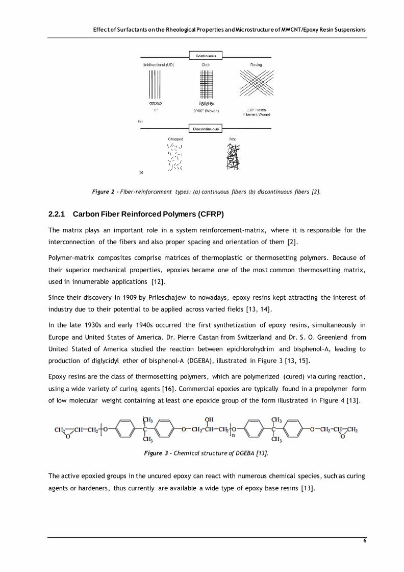
element to improve overall properties of composites. There are two types of fibers (see Figure 2),
continuous and discontinuous fibers, where the first one has long aspect ratios and a preferred
orientation, and second one has short aspect ratios and a random orientation [2].
Figure 1 - Schematic of aligned CNT polymer nanocomposite. Indication of the poor conductivity in-plane direction and the
high conductivity through-thickness direction.
Effect of Surfactants on the Rheological Properties and Microstructure of MWCNT/Epoxy Resin Suspensions
6
2.2.1 Carbon Fiber Reinforced Polymers (CFRP)
The matrix plays an important role in a system reinforcement-matrix, where it is responsible for the
interconnection of the fibers and also proper spacing and orientation of them [2].
Polymer-matrix composites comprise matrices of thermoplastic or thermosetting polymers. Because of
their superior mechanical properties, epoxies became one of the most common thermosetting matrix,
used in innumerable applications [12].
Since their discovery in 1909 by Prileschajew to nowadays, epoxy resins kept attracting the interest of
industry due to their potential to be applied across varied fields [13, 14].
In the late 1930s and early 1940s occurred the first synthetization of epoxy resins, simultaneously in
Europe and United States of America. Dr. Pierre Castan from Switzerland and Dr. S. O. Greenlend from
United Stated of America studied the reaction between epichlorohydrim and bisphenol-A, leading to
production of diglycidyl ether of bisphenol-A (DGEBA), illustrated in Figure 3 [13, 15].
Epoxy resins are the class of thermosetting polymers, which are polymerized (cured) via curing reaction,
using a wide variety of curing agents [16]. Commercial epoxies are typically found in a prepolymer form
of low molecular weight containing at least one epoxide group of the form illustrated in Figure 4 [13].
The active epoxied groups in the uncured epoxy can react with numerous chemical species, such as curing
agents or hardeners, thus currently are available a wide type of epoxy base resins [13].
Figure 2 - Fiber-reinforcement types: (a) continuous fibers (b) discontinuous fibers [2].
Figure 3 - Chemical structure of DGEBA [13].

Effect of Surfactants on the Rheological Properties and Microstructure of MWCNT/Epoxy Resin Suspensions
7
When compared to other thermosetting polymers, epoxy resins are quite more expensive, although show
they better mechanical properties and higher resistance to chemical and environmental corrosion and
moisture absorption. Moreover, they show high electrical resistivity and good performance at elevated
temperatures because of their higher heater deflection and glass transition temperatures. Epoxy resins
also have a good adhesion capacity to other components/substances, due to the polar groups, which
make them ideal matrices to formulate new materials. Another positive aspect resides in the fact that
during curing process, there is not emission of dangerous compounds and the resins does not suffer a
significant volume contraction [17].
They also have toughness, good adhesion to other materials, mechanical and corrosion resistance, which
make these resins suitable for industrial tooling, aerospace industry, electronic materials, biomedical
devices, paints and coatings [13, 18].
2.2.2 Carbon Nanofiller Composite Materials
The versatility of the chemical element carbon enables to form distinct structures with different
characteristics. Its potentiality has attracted much attention, especially in the composite materials field,
as a reinforcement component. Among carbon-type reinforcement materials, carbon nanotubes (CNTs)
have been extremely used because of their incredible capacity to be incorporated with different
materials, giving rise to a variety of composite materials with enhanced properties.
Since their discovery in 1991 by Iijima, carbon nanotubes have been commonly used as reinforce
materials because of their mechanical, thermal and electrical characteristics [19-22]. CNTs are
cylindrical molecules composed by carbon atoms, with a typically hexagonal structure that repeats itself
periodically in space, leading to atoms bonded to three neighbor atoms, as illustrated in
Figure 5 [23, 24].
CNTs can assume two forms: single-walled carbon nanotubes (SWCNTs) or multi-walled carbon nanotubes
(MWCNTs), which are composed of concentric SWCNT (see Figure 6) [24]. SWCNTs are usually stronger
than MWCNTs, with a diameter in order of few nanometers. Diameters of MWCNTs ranging from 10
Figure 4- Chemical structure of epoxide group, which the oxygen atom is attached by single bonds to two adjacent
carbon atoms, forming a cyclic ether with a three-atom ring. The R is a radical and represents any subgroup of
atoms [13].
Figure 5 - Molecular structure of a section of CNT [23].

Effect of Surfactants on the Rheological Properties and Microstructure of MWCNT/Epoxy Resin Suspensions
8
nanometers to 200 nanometers [20, 24, 25]. The exact properties of CNTs are extremely influenced by
their degree of graphitization, diameter and whether if are in single-wall or multi-wall form [26].
Although, according to the literature [27], individually, CNTs can show Young’s moduli ranging from 270
GPa to 2 TPa and tensile strength ranges from 11 GPa to 200 GPa, which makes them ideal
reinforcements. They also have failure strains of up 15% and electrical conductivity that depends on their
structure, ranging from semiconducting to metallic. Their surface area is around 10–20 m2/g and their
thermal stability in air is higher than 700 ºC [28]. Studies revealed that SWCNT shows an electrical
conductivity around 102–106 S.cm-1 and thermal conductivity around 6000 W.m-1.K-1. In other hand,
MWCNT has shown an electrical conductivity around 103–105 S.cm-1 and thermal conductivity around 2000
W.m-1.K-1 [29].
In spite of CNTs superior properties, when compared with conventional materials and their unique
nanostructure, these carbon fillers present some limitations: the poor dispersion in polymeric matrices,
which limits the extent of realizing potential improvements in polymeric composites area, and their high
cost [30, 31]. Several studies reported an increase in viscosity, which may lead to problems in processing,
with regard to adequate mixing and operation temperature, that could affect the final properties of the
composite [20, 32, 33].
The literature does not show a consensus regardless to increasing of suspensions viscosity, as detailed in
the next sections.
2.2.3 Processing of Carbon Nanotube-Polymer Composite Materials
One important aspect when producing a nanocomposite is to achieve a good dispersion of fillers in a
matrix, regardless of their size or shape. Without a good dispersion, the nanofiller tends to agglomerate,
forming aggregates that act like local flaws which limit the mechanical performance of nanocomposite
and influence its final properties [34]. Therefore, one of the challenges of processing CNT suspensions
is achieving good quality dispersion of the filler into the polymeric matrix. Three distinct approaches are
generally used for dispersing carbon nanofillers:
• Mechanical methods;
• Use of organic solvents;
• Methods designed to modify CNT surface (functionalization), which can be chemical (addition of
the functionalization group) or physical (addition of surfactants).
Figure 6 - Representation of (a) SWCNT and (b) MWCNT. SWCNT is formed by a single curved layer of graphene. MWCNT
is constitute by concentric SWCNT, forming a complex structure [24].

Effect of Surfactants on the Rheological Properties and Microstructure of MWCNT/Epoxy Resin Suspensions
9
Mechanical approaches, such as ultrasonication and high shear mixing, involve the separation of CNTs
from each other, however higher frequencies/shear mixing can fragment them, and decreasing their
aspect ratio [26].
The physical-chemical aspects behind dispersion of CNTs using organic solvents are not totally clarified,
being an area in current investigation [35]. Furthermore, organic solvents cause processing more
challenging and expensive, because it involves another process step, solvent separation.
Methods designed to change the surface, as mentioned above, can be either chemical or physical.
Chemical functionalization of CNTs involves the addition of the functional group covalently bonded to
CNT surface (such as CO, CO2, NH3…) and are used to improve their chemical compatibility with the
polymeric matrix, by covalently bonding with the epoxydic group of epoxy pre-polymer, resulting in an
improve of adhesion, wetting or reduce their tendency to aggregate [26, 29]. Although, aggressive
chemical treatment, such as strong acid treatments or high temperature methods, can damage the CNT’s
structure, changing the hybridization from sp2 to sp3 and losing the ð-conjugation system. Thus, in this
case, the agglomerates of CNTs may act as defects/flaws in the composite and consequently they lead
to inferior final properties [29, 36].
To avoid these problems, physical methods, like non-covalent treatment by surfactants, are particularly
important. These methods allow the CNT surface to adsorb functional groups without disturbing the π
system (no covalent bond is made) [26]. Both CNTs and surfactant play an important role in dispersing.
The nature, concentration and the type of interaction of surfactant and the surface charge of CNT are
essential for understanding the adsorption mechanism [26].
2.3 Surfactants
Surfactants are amphiphilic molecules consisting of at least two parts structurally distinct, one which is
soluble in a specific solvent and another is insoluble in that same solvent (see
Figure 7). These molecules have the capacity to adsorb at a surface or at an interface between two
different phases, reducing the interfacial Gibbs energy, i.e., reducing the surface tension or interfacial
tension of the system [37].
To avoid the contact between regions with different polarities, surfactants tend to form aggregates with
distinct forms (micellar structure, laminar structure or cubic structure). The micellar structure is
illustrated in Figure 8 [38]. The critical concentration, in water, at which this structures begin to form
is called critical micelle concentration (CMC) [37].
Figure 7 - Schematic illustration of a surfactant [37].

Effect of Surfactants on the Rheological Properties and Microstructure of MWCNT/Epoxy Resin Suspensions
10
According to the literature [26, 39-41], because of their structure which promotes the affinity to adsorb
to CNTs surface, these agents are currently being tested to analyze their effect in the dispersion of CNTs
into polymeric matrices as an alternative to covalent functionalization.
2.3.1 Dispersing Carbon Nanotubes using Surfactants
The quality of the dispersion is subjective, but the ideal dispersion consists in a higher fraction of isolated
fillers in suspension. Pure epoxy pre-polymer is polar and CNTs are non-polar, which makes their
individual dispersion a difficult task. Due to physical-chemical properties of surfactants, recently they
have been explored as CNT dispersants. For mixtures without the presence of surfactants, the
suspensions may be unstable and the fillers tend to rebounding through Van der Waals forces. If the
surfactant is present, it is adsorbed along the filler length in an unzipping mechanism, i.e., its non-polar
head interacts with the wall of the tube through Van der Waals forces, which allows the full separation.
Figure 9 shows the interaction of a surfactant with CNTs [40]. The adsorption strength is critically
important and it is given by the hydrophobic interactions with the tube wall. Although, despite all studies
there is no definitive understanding of the dispersion mechanisms and the structure of surfactants [42].
A common studied CNT dispersant is Triton X-100. It is a non-ionic surfactant, which its non-polar head
consists in a benzene ring and an alkane chain. Because of its chemical structure, and in comparison with
other dispersants, Triton X-100 seems to have a better interaction with the surface of CNT and a better
compatibility with epoxy resin [40].
Figure 9 – Schematic illustration of the interactions between Triton X -100 and the wall of a MWCNT [40].
Figure 8 - Schematic representation of surfactant aggregates in water [38].

Effect of Surfactants on the Rheological Properties and Microstructure of MWCNT/Epoxy Resin Suspensions
11
2.4 Rheology
The addition of reinforcement components, such as carbon fillers, in polymeric matrices allows to
improve the properties of the final material (composite). Although, some issues are known to may cause
processing problems. The problems associated to dispersion and the increase in viscosity of CNT/epoxy
suspensions are aspects that many researches have been looking at. In order to optimize the filler/epoxy
mixtures and minimize those processing problems, rheological features can be evaluated.
Rheology is defined as the science of flow and deformation of materials (solid, liquid or gas) under the
influence of stresses [43, 44].
Every type of flow is resisted by viscosity, consequently to maintain the flow of a fluid it is necessary to
add energy. Ideal elastic solids suffer an elastic deformation, where the energy required for the
deformation is fully recovered when the stresses are removed. However, ideal fluids suffer an irreversible
deformation, where the energy required for the deformation is dissipated within the fluid in the form of
heat. The majority of liquids show a rheological behavior that classifies them in a region between solid
and liquid (viscoelastic) [43]. There are two types of flows with relative movement of adjacent liquid
particles: shear flow, where liquid elements flow over or past each other, and extensional flow, where
liquid particles flow towards or away from each other (see Figure 10) [44].
2.5 Materials Behavior
2.5.1 Ideal Elastic Behavior
Ideal elastic materials respond to applied external forces by changing its internal structure. If the
provided stress is sufficiently small, the material recovers its original structure when the force is
removed. However, if the force applied is larger enough the material’s structure yields and the
deformation is permanent. This deformation behavior is formally described using Hooke’s Law [45]:
𝜏 = 𝐺×�̇� (1)
This behavior shows a linear relationship between stress and strain and the response of the material to
stress is instantaneous. Shear modulus (G) reveals information about the rigidity of a material, if its
Figure 10 - Schematic of shear and extensional deformation and flow [44].

Effect of Surfactants on the Rheological Properties and Microstructure of MWCNT/Epoxy Resin Suspensions
12
intermolecular forces show higher internal rigidity, the material has a higher value of shear
modulus [45].
2.5.2 Ideal Viscous Behavior
The response of ideal viscous materials, in comparison to ideal elastic materials, is delayed when the
stress is applied and, contrary that what is observer in ideal elastic behavior, the materials do not recover
their original shape. The basic law of viscometry describing the flow behavior of an ideal viscous material
is given by the Newton’s Law [43, 45]:
𝜏 = 𝜂×�̇� (2)
Dynamic viscosity (η) is given by the ratio between shear rate (�̇�) and shear stress (τ) ratio. Shear stress
is defined as a force applied tangentially to an area. The velocity of flow that can be maintained for a
given force is controlled by the internal resistance of the material (viscosity) [43]. Shear rate describes
the gradient of the velocity in the normal direction to the flow [44].
2.5.3 Newtonian and Non-Newtonian Behavior
Figure 11 illustrate all types of flows of a Newtonian and non-Newtonian liquid [43]. Due to the straight
line of curve flow, shear rate and shear stress ratio values are constant, which means that viscosity is
not affected by changes in shear rate. Therefore, all liquids that follow this behavior are called
Newtonian liquids. All fluids that do not exhibit a Newtonian behavior are called non-Newtonian
fluids [43].
Pseudoplasticity or shear thinning behavior are terms used to describe the decrease of viscosity of a fluid
when shear rate increases. Shear thickening behavior or dilatancy describe the increase of viscosity when
shear rate increase. Examples of a shear thinning fluid and a shear thickening fluid are ketchup and
quicksand, respectively.
2.5.4 Viscoelastic Behavior
A viscoelastic material always shows an elastic and viscous behavior simultaneously. When a stress is
applied, the material will always suffer a deformation, which the extent of the deformation represents
the elastic portion and the extent of permanently remaining deformation corresponds to the viscous
Figure 11 - Types of flow behavior of non-Newtonian liquids [43].
Effect of Surfactants on the Rheological Properties and Microstructure of MWCNT/Epoxy Resin Suspensions
13
portion. This deformation process is irreversible, the material changed its structure at the end of the
process because it does not recover its original form [45].
The yield stress consists in the stress corresponding to the transition from elastic to plastic deformation.
Samples with yield point only began to flow when the external forces acting on the material are larger
than the internal structural forces. Thus, bellow the yield stress the material reveals an elastic behavior
and no flow is observed, which under load shows a small degree of deformation that does not remain
after the removal of the stress [45, 46].
2.5.5 Linear Viscoelasticity
All materials internal structure has a natural rest condition that represents a minimum-energy state.
When deformed, thermodynamic forces immediately begin to operate to restore the minimum-energy
state. This movement from the rest state represent a storage energy which is the origin of elasticity of
many materials. Thus, the deformation energy stored in the sample during the shear process is given by
storage modulus and the deformation energy used up in the sample during the shear process is given by
loss modulus [45].
Linear viscoelasticity is the simplest response of viscoelastic materials, where the microstructure
responds over a certain time scale without changing [44]. This region can be determined by performing
an oscillation amplitude sweep test, applying a constant and reduced angular frequency and increasing
the strain over time.
2.6 Aspects of Rheometry
Rheometry is understood as the field of knowledge that involves any technique used to measure
mechanical or rheological behavior of a material. These properties are evaluated using a rheometer,
which consists in an equipment that can exert a torque (force that can induce the rotation of an object)
or force on a material and accurately measures its response.
This equipment is commonly used in industry and research to provide information related to process
engineering, quality control, product development and others. However, today, rheological
measurements represent a standard method to determine viscoelastic properties of materials.
2.6.1 Methods of Measuring Materials Behavior
There are many ways to measure the response of materials. Rheological measurements can be static or
dynamic. Static methods involve the application of a step change in strain or stress and the observation
of material’s response over time [47]. Static measuring methods are divided into two categories: creep
and flow-ramp tests. Creep experiments consist in an application of a constant stress in a period,
followed by the removal of that stress. The material’s response is monitored with time. Flow-ramp tests
involve the application to the material of a constant increasing or decreasing stress or shear rate, from
an initial to a final stress or shear rate level, continuously or in steps.

Effect of Surfactants on the Rheological Properties and Microstructure of MWCNT/Epoxy Resin Suspensions
14
Dynamic methods involve the application of a harmonically varying torque [47]. Thus, material’s behavior
can be divided into a time-independent part (elastic) and a time-dependent part (viscous). Three types
of experiments can be employed [48]:
• In constant-oscillation tests, the applied stress and the oscillatory frequency are constant.
• In amplitude sweep measurements, the stress is increased or decreased over time, while
oscillation frequency is held constant.
• In frequency sweep test, the applied stress is constant and the oscillation frequency is increased
or decreased with time.
Rheological analysis can be employed as a sensitive tool in predicting the physical properties of
materials and understanding the rheological properties can help to develop improved materials,
since physical properties are usually linked to material’s formulation and processing.
Through the rheological experiments mentioned above, several rheological parameters can be evaluated
and some specific parameters characteristic of each material can be determinate, such as yield stress,
thixotropic index, storage and loss modulus etc.
The storage modulus characterizes the ‘solid-like’ component of a material at any particular frequency
and the ‘liquid-like’ response is characterized by the complementary loss modulus (G’’) [44]. The yield
stress, as mentioned in Section 2.5.4, corresponds to the stress required to induce plastic deformation
and it is a significant factor for several industrial processes. The phenomenon where a continuous
decrease of viscosity with time is observed when a stress is applied to a sample that has been previously
at rest and the subsequent recovery of viscosity in time when the flow is discontinued is called
thixotropy [49]. This parameter is an indicative of a material’s ability to maintain its shape and is also
an important aspect in several processes. The representations of yield stress and thixotropy are
illustrated in Figure 12 (A) and Figure 12 (B), respectively [50].
2.7 Rheology of Carbon Nanotube Suspensions
It is expected that rheological behavior of CNTs suspensions will depend of its network structure, CNT
concentration, CNT aspect ratio, and even orientation and dispersion state and interrelations between
these parameters [20, 22, 51].
Yield
stress
Figure 12 - Schematic representation of material's (A) yield stress and (B) thixotropy [50].

Effect of Surfactants on the Rheological Properties and Microstructure of MWCNT/Epoxy Resin Suspensions
15
Concentration of CNT in a suspension is an important aspect to considerer. A higher CNT concentration
(up to a certain limit) combined with good dispersion suggest more and stronger interactions among CNT
due to shorter distances between them. Thus, increasing the CNT concentration leads to the appearance
of suspension gel behavior, which is translated by the increasing in magnitude of suspension viscosity, G’
and G’’ at a fixed strain and within the linear viscoelastic region. Beyond a certain value a plateau is
observed, usually at low frequencies. The critical concentration at which this phenomenon is observed
(as a result of a formation of a space-filling network) is defined as threshold value (i.e., rheological
percolation threshold) [20, 32].
There is no apparent consensus on percolation thresholds of CNT/polymer materials, the values reported
in the literature [52] for typical multiwall CNT/epoxy nanocomposites vary from 0.002 to over
4.0 % (m/m). Some studies have described the rheological percolation as a sudden modification in
rheological properties of the material on account of the onset solid-like behavior, which is triggered by
network formation of filler. An existence of a low-frequency G’ plateau in oscillatory tests is an indication
of a rheological percolation associated to the formation of a solid-like network of filler [53, 54]. The
literature [55] reviewed suggest that the percolation threshold may depend on the processing method,
polymer matrix and filler type.
Despite all studies that were conducted, the literature does not clarify well the relationship between
CNT dispersion and physical network and the improvement of the rheological behavior of epoxy
composites.
2.7.1 Effect of Carbon Nanotube Concentration
In rheology, volume-per-fraction is often used in defining concentration rather than weight-per-fraction.
In rheology, phase volume is important because it is dependent of the hydrodynamic forces that act on
the surface of particles or aggregates, regardless of particle density [47]. However, usually for CNT
nanocomposites it is reported the concentration in weight-per-fraction, which is useful to compare
mechanical and rheological properties between composite materials and metals or even ceramics.
Allaoui et al. (2002) [56] demonstrated the potential of the MWCNTs. The report showed that the addition
of 1 and 4 % (m/m) of CNT in the epoxy resin has increased G’ and yield strength. They also stablished a
relation between the CNT dispersion and the mechanical behavior of nanocomposite, concluding that
higher CNT content (4.0 % (m/m) MWCNT) promotes a poor dispersion and the formation of CNT
aggregates and consequently a reducing of G’. Song et al. (2005) [57] conducted experiments that showed
an increase of G’ as CNT concentration increases for composites with well dispersed CNTs, and a decrease
of G’ for composites with poorly CNTs dispersion. Fan et al. (2007) [20] demonstrated the increase of
viscosity and complex viscosity at a given shear rate and frequency, respectively, with the increasing of
CNT content. Yearsley et al. (2012) [58] verified the increase of G’ as CNT content increases at a certain
shear rate and the formation of CNT aggregates at lower shear rates that were posteriorly broken down
at higher shear rates.
Mun et al. (2014) [59] conducted dynamic shear rheology tests to characterize polymer-based materials
(polycarbonates) and observed an increase of G’ and G’’ with the increasing of CNT concentration,
although the increment of G’’ was less significant, which indicated that the network formation of CNT

Effect of Surfactants on the Rheological Properties and Microstructure of MWCNT/Epoxy Resin Suspensions
16
contributed more to the yielding or solid-like behavior than to viscous nature. Chang et al. (2016) [33]
reported that CNT tend to form domains constitute by CNT aggregates, that when subjected to an
increasing shear rate they tend to swelling, allowing a better interaction between CNT and resin and
leading to the increasing of viscosity. Thus, they showed that the increase of CNT content increases the
viscosity of suspension at a given shear rate, which has been associated with the domain size that CNT
aggregated in the epoxy resin.
2.7.2 Effect of Carbon Nanotube Dispersion and Physical Network
Song et al. (2005) [57] investigated the influence of CNT dispersion and reported that suspensions
containing CNTs poorly dispersed presented higher G’’, G’ and complex viscosity than well dispersed
suspensions. On the contrary, Fan et al. (2007) [20] claimed that epoxy resins with well dispersed CNTs
exhibit higher G’ and G’’ than suspensions poorly dispersed. According to the research group, due to a
strong Van der Waals force between CNTs, they tend to agglomerate and form a non-uniform CNTs
aggregates in the continuous phase. CNTs network structure played an important role in CNTs suspension
rheology and was classified from two aspects: CNT separation and interconnection. In other words, the
structure was defined as a mixture of individually separated CNTs and CNTs aggregations that are
interconnected with each other, forming an entangled network. Thus, they defined a good dispersion
system as a state that at the lower end has CNTs aggregates which are uniformly dispersed in the
continuous phase and at the highest end has individual separated CNTs in the suspending liquid [20, 60].
Moreover, Fan et al. (2007) [20] studied the formation of CNTs network, comparing similar samples
subjected to different agitation times. The agitation allowed to separate, uniformly and individually, the
CNT and as result the physical network was changed. They found out that G’ and complex viscosity are
very sensitive to network structure and a small change resulted in different responses of those
parameters.
Rahatekar et al. (2006) [61] linked the optical microstructure observations with the rheological
properties of a CNT/epoxy resin suspension. They concluded that the high viscosity at low shear rates is
the result of the presence of interconnections between CNTs aggregates and the shear thinning at high
shear rates is the result of the breakage of those interconnections. Chapartegui et al. (2010) [46]
reported a physical network formation for CNTs concentration above 0.13 % (m/m), resulting from CNTs
interactions. A viscosity reduction as shear rate increases combined with an existence of a shear thinning
behavior, revealed that the physical structure was destroyed when the shear was imposed. Evidences of
destruction of the network were not noticed in dynamic viscoelastic measurements, suggesting a rapid
recovery of the physical network.
2.7.3 Effect of Carbon Nanotube Content on Specific Rheological Parameters
No specific studies about rheological parameters characteristic of epoxy/CNT suspensions, such as yield
stress, thixotropic index and critical angular frequency (crossover frequency), were found on the
literature, however some papers refer some conclusions about yield stress for these systems.
Chapartegui et al. (2010) [46] reported an increase of sample’s yield stress with the increasing of CNT
concentration, but did not establish a relation with other rheological properties. On the other hand,
Martin-Gallego et al. (2013) [62] related the suspension’s yield stress with the physical network

Effect of Surfactants on the Rheological Properties and Microstructure of MWCNT/Epoxy Resin Suspensions
17
formation. The research group observed a tendency of yield stress to increase with the CNT amount,
which was attributed to the increase of network strength with the increasing of fillers content.
Reports about critical frequency of epoxy/CNT systems were not found, however were found some
references for polycarbonates/CNT suspensions. Mun et al. (2014) [59] obtained an increase of modulus
crossover with the increase of CNT loading and justified the data as changes in chain mobility and
relaxation.
2.7.4 Effect of Surfactants as a Non-Covalent Functionalization of Carbon Nanotubes
The literature does not report a study mainly focused on the effect of surfactants on rheological
properties of epoxy/MWCNT materials. Simcha et al. (2012) [36] proceeded to the characterization of
MWCNT nanocomposites, having tested, among all the samples, the effect of the use of the surfactant
Triton X-100. All the samples had the same quantity of surfactant, varying only the CNT content. The
research group obtain for a given MWCNT content, a higher suspension viscosity for the samples with
untreated MWCNTs (without surfactant), being that increase more pronounced for higher MWCNTs
contents. This led them to conclude that the surfactant allowed a better dispersion of MWCNTs, due to
the reduced value of viscosity. Relative to G’, they also obtained a value increase, for the samples
functionalized with Triton X-100, with the increasing of MWCNTs.


Effect of Surfactants on the Rheological Properties and Microstructure of MWCNT/Epoxy Resin Suspensions
19
3 Materials and Methods
3.1 Materials
The selected polymeric-matrix was DGEBA epoxy pre-polymer Araldite LY556 from Huntsman
Corporation (Europe) with a viscosity of 10-12 Pa∙s and a density of 1.15-1.20 g.cm-3. The MWCNTs
Graphistrength C100 (>90%) with an outer diameter of 10-15 nm (5-15 walls) and length of 1-10 µm, were
obtained from Arkema.
To obtain a nanocomposite, the MWCNT/epoxy suspensions were mixed with a mixture of hardeners:
Aradur 1571, Accelarator 1573 and XB 3903, all from Huntsman Corporation (Europe).
Three distinct surfactants were employed in the experimental procedure and their characteristics are
presented in Table 1:
• Triton X-100 (TX100) from VWR Chemical (typically used for this type of suspensions because of
the good results obtained so far);
• Sodium dodecylbenzene sulphonate (SDBS) from MP Biomedicals (selected because of its high
polarity);
• Poly(propylene glycol) monobutyl ether (PPGMBE) from Sigma-Aldrich (selected because of its
affinity to CNTs and its high molecular weight).
Table 1 - Characteristics of the surfactants used.
Type Chemical Structure
Molecular
Weight
(g.mol-1)
Characteristic
Critical Micelle
Concentration
(mmol.dm-3)
n
Triton X-100
(TX100)
646.84 Non-Ionic 0.22-0.24 10
Sodium
dodecylbenzene
sulphonate (SDBS)
348.48 Anionic 1.8 -
Poly(propylene
glycol) monobutyl
ether (PPGMBE)
1000 Non-Ionic - 16

Effect of Surfactants on the Rheological Properties and Microstructure of MWCNT/Epoxy Resin Suspensions
20
3.2 Preparation of Epoxy/MWCNT Suspensions
The experimental work involved the preparation of epoxy/MWCNT suspensions with different contents
of filler, between 0 and 1.0 % (m/m). The MWCNTs were added to the neat epoxy and subjected to
mechanical stirring and then processed in a calendaring-type equipment - three-roll mill. Both mixing
techniques are described in detail in Section 3.2.1.
To evaluate the effect of surfactants on rheological properties, mixtures of 1.0 % (m/m) MWCNT/epoxy
were prepared with different concentrations of Triton X-100, SDBS and PPGMBE, as presented in
Table 2.
Table 2 - Compositions of the formulations prepared.
MWCNT Content (% m/m)
Triton X-100 Content (% m/m)
SDBS Content (% m/m)
PPGMBE Content (% m/m)
0 0 0 1.0
0.06 0.00012 (1.0 CMC) 0.00057 (1.0 CMC) 2.0
0.125 0.0029 (20.0 CMC) 1.0 (20.0 CMC) 10.0
0.25 1.0 1.5 -
0.375 1.5 2.0 -
0.5 2.0 5.0 -
0.75 5.0 10.0 -
1.0 10.0 - -
The MWCNTs and the surfactant were added to the resin and then the mixtures were processed as
mentioned above (mechanical stirring and three-roll mill). After the processing of epoxy/MWCNT
suspensions, the rheological measurements were performed and boards were cured for optical
microscopy and electrical analysis.
3.2.1 Approaches for Mixing and Dispersing Carbon Nanotubes
The primal approach for mixing the carbon fillers in the polymeric matrix was the mechanical agitation,
using a mechanical stirrer CAT R100C. The blade employed for this task was a dispersing homogenizer
blade, indicated for high shear mixing, with a diameter of 35 mm. The mechanical stirrer and the blade
are illustrated in Figure 13.
However, the mixture provided by this mechanism may not be as efficient as necessary, existing several
locations, mainly near the recipient walls, called dead zones, where the dispersing is not improved.
Furthermore, other methods may be used and even combined with the techniques mentioned before.
Thus, another method was employed to promote a better dispersion of carbon nanotubes: the
calendering process.

Effect of Surfactants on the Rheological Properties and Microstructure of MWCNT/Epoxy Resin Suspensions
21
Unlike other types of mills which rely on compressive impact as well as shear, the calendaring approach
results in nearly pure shearing [63]. In this dissertation, this was the method used to assure an efficient
dispersion of CNTs in the matrix.
The use of calender, or commonly known as three-roll mill, consists in a standard method for dispersing
micro and nano-scaling particles [64]. This equipment employs a shear force created by rollers to mix,
disperse or homogenize viscous materials. The general configuration of the machine consists of three
adjacent rolls which rotate at different velocities. The feeding roller (n1 in Figure 14 (B)) and the apron
roller (n3 in Figure 14 (B)) runs in the same direction, while the center roller (n2 in Figure 14 (B)) rotates
at the opposite direction [29].
As illustrated in Figure 14 (B), the material is fed between the feed and the center rollers where it will
be pre-dispersed. After that, the material sticks to the bottom of the center roller, which transports it
into the second gap, where the material is dispersed to the desired degree of fineness. The material that
remains in the center roller moves through the second nip between the center and the apron rollers ,
which subjects it to even higher shear force due to the higher speed of the apron roller. A sharp blade
collects the mixed material from the apron roller and transfers it to the apron [29]. This cycle can be
repeated to promote a better dispersion.
For the preparation of epoxy/MWCNT mixtures was used the model EXAKT 80E (EXAKT GmbH, Germany),
illustrated in Figure 14 (A). The processing in three-roll mill was carried out at room temperature in five
steps, all at the same rotation velocity and varying the gap between the rollers, with the procedure
Figure 14 - (A) Calender (or three roll mill) machine and (B) schematic of configuration of calender machine, where n1
represents the feeding roller, n2 is the center roller and n3 represents the apron roller [29].
Figure 13 - (A) Mechanical stirrer and (B) Dispersing homogenizer blade.
(A) (B)
(A) (B)

Effect of Surfactants on the Rheological Properties and Microstructure of MWCNT/Epoxy Resin Suspensions
22
presented in Table 5 (in Appendix 1). In each step, the mixture was milled five times to obtained a
homogeneous suspension.
3.3 Preparation of Cured Nanocomposites Boards
To obtain a cured nanocomposite boards for microscopy and electrical conductivity analysis, a mixture
of hardeners was added into the epoxy/MWCNT suspensions. The mixtures of hardeners consist of
Aradur 1571 (23:100) and Accelarator 1573 (5:100), and was prepared using a mechanical stirrer at 100
rpm. Then the hardener XB 3903 (12:100) was added, which was also mixed using a mechanical s tirrer at
1000 rpm. After that, that material was casted into the mold, and cured in the oven for 2 hours at
120 ºC. In the end, a 10 cm x 10 cm cured nanocomposite board with approximately 2 mm of thickness
is obtained, as illustrated in Figure 15.
3.4 Rheological Characterization
3.4.1 Summary of the Experiments
The rheometer model used in this thesis was Discovery Hybrid Rheometer-1 from TA Instruments (see
Figure 16). All characteristics of the equipment are described in Table 6 (Appendix 2).
Flow-ramps and small amplitude oscillatory flow measurements were carried out in a rheometer, using
a plate-plate geometry of 25 mm diameter and 1 mm gap.
All experiments were run at 25 ºC and each rheological test was performed on freshly loaded samples.
Flow ramp tests with a shear rate from 0.0085 s -1 to 1150 s-1 were carried in four steps, where the first
and the third steps were run with an increasing shear rate (0.0085 s -1 to 1150 s-1) and the second and
fourth steps were run with a decreasing shear rate (1150 s -1 to 0.0085 s-1). Each step has a duration of 60
seconds. This steady state measurements allowed the determination of dynamic viscosity, thixotropic
index and yield stress.
Oscillatory rheology tests were performed in the linear viscoelastic (LVE) regime (experiment described
in Section 3.4.2), where the microstructure of the samples responds without changing.
Figure 15 - Nanocomposite obtained after the cure process.

Effect of Surfactants on the Rheological Properties and Microstructure of MWCNT/Epoxy Resin Suspensions
23
Frequency sweeps from 115 rad.s -1 to 0.01 rad.s-1 were applied at a strain within the linear viscoelastic
region. This dynamic experiment allowed the determination of storage modulus, loss modulus, complex
viscosity and modulus crossover (G’ = G’’).
3.4.2 Determination of the LVE Regime
To determine the viscoelastic regime, oscillation amplitude sweeps must be performed for each sample,
resulting in a graph presented in Figure 17 (corresponding to the sample 1.0 % (m/m) MWCNT/epoxy).
The limit for linear viscoelasticity was obtained from an amplitude sweep at a constant angular
frequency (ω) of 10 rad.s-1 and varying the strain between 0.0125 % and 12.5 %.
The viscoelastic region corresponds to the range of strain where G’ values do not change drastically. In
the example presented in Figure 17, the LVE region corresponds to the range of strain between
approximately 0.7 % and 3 %.
Figure 17 - Oscillation amplitude sweep result.
3.4.3 Determination of Thixotropic Index
The systems that satisfy the definition of thixotropy can be identify through several rheological features,
but also through physical properties, such as optical and electric features, due to the changing in the
microstructure with the shear history that affects the mechanical response. One rheological feature used
often is the hysteresis technique. It consists in increasing and decreasing shear rate between zero and a
Figure 16 - Hybrid rheometer-1 from TA Instruments used to perform all rheological experiments.
10-1
100
101
2x10²
4x10²
6x10²
8x10²
103
Sto
rag
e M
od
ulu
s G
' (P
a)
Lo
ss M
od
ulu
s G
'' (
Pa)
Oscillation Strain (%)
Storage Modulus G' Loss Modulus G''

Effect of Surfactants on the Rheological Properties and Microstructure of MWCNT/Epoxy Resin Suspensions
24
maximum value, continuously or in steps [49]. When the stress is plotted against shear rate, a thixotropic
sample will form a hysteresis loop, as shown in Figure 18.
For a viscoelastic solid material, under cyclic loading and unloading they exhibit hysteresis which leads
to a dissipation of mechanical energy per volume, that corresponds to the area within the hysteresis loop
[65]. In polymeric solutions, the level of elasticity and viscosity is given by entanglement density, thus
for MWCNT/epoxy suspensions, the microstructure is associated to the entanglement of epoxy chains and
the alignment and favorable distribution of CNTs. The maximum microstructure is observed when the
alignment and distribution of fillers are random and entanglement density is maximum [66]. Therefore,
the area within the hysteresis loop corresponds to the energy consumed in microstructure breakdown
(disentanglement of polymeric chains and alignment of filler with flow direction). This energy is obtained
by calculating the integral of each experimental curve.
Figure 18 - Hysteresis loop of a thixotropic material.
3.4.4 Determination of Yield Stress
Several empirical equations have been proposed to determine the yield stress of viscoelastic systems. In
this case, the linearization of stress-shear rate flow curves is very well reached with the Casson Model
given by Equation (3) [67]:
𝜏0.5 = 𝜏𝑐0.5 + (𝜂𝑓 . �̇�)
0.5(3)
This model gives a straight line when 𝜏0.5 (stress) is plotted against �̇� 0.5 and yield stress (𝜏𝑐 ) and final
constant viscosity (𝜂𝑓) values for each sample correspond to the square of the intercept and square of
the slop, respectively.
3.4.5 Determination of Critical Angular Frequency
The variation of concentration of a polymer solution can be reflected in the viscoelastic properties.
Therefore, the addition of carbon nanofillers into an epoxy resin in different contents may also affect
the viscoelastic properties of the material. For a viscoelastic system, the frequency over which shear is
applied becomes a critical determinant and defines whether viscous or elastic portion is dominant. In
dynamic measurements, the crossover of G’ and G’’ on abscissas axis represents the change in the mode
of relaxation of material with a characteristic time scale which is controlled by the interactions between
fillers [68].
10-2
10-1
100
101
102
103
101
102
103
104
Str
es
s (
Pa)
Shear Rate (s-1)

Effect of Surfactants on the Rheological Properties and Microstructure of MWCNT/Epoxy Resin Suspensions
25
3.5 Characterization of Carbon Nanotubes Nanocomposites
3.5.1 Optical Microscopy
For a better understanding of CNT distribution in epoxy matrix and dispersions quality of the
nanocomposites produced, i.e., to evaluate the influence of different types and loadings of surfactant
on the dispersion level and the distribution of epoxy-based nanocomposites containing 1.0 % (m/m)
MWCNTs, optical microscopy was used. Images with a good resolution and with sufficient contrast
between CNTs and epoxy matrix were obtained to observe the different samples.
The optical microscopy analysis presupposed the prior preparation of the cured samples. Thin sections
of approximately 5 µm were cut using a microtome Leitz 140 fitted with a glass knife at 45° and at room
temperature. Optical micrographs were taken using a Leica DFC 280 digital camera coupled to a BH2
Olympus microscope in transmission mode, using a 1.6x ocular magnification and 20x objective.
Quantitative particle analysis was performed by a digital image processing software ImageJ. At least 15
images were considered for the statistical analysis, corresponding to an observed area of 5.2×106 µm2.
The equations for the statistical analysis are presented in Appendix 3.
3.5.2 Electrical Properties
Electrical property of nanocomposites was measured to verify if the addition of MWCNTs led to an
improved material. The electrical analysis presupposed the prior preparation of the cured samples. The
material was initially sanded to obtain a polish and adequate surface for the measurement. Then, two
Au/Pd electrodes with 3 mm of diameter were placed in the two faces of the sample parallelly.
Electrical conductivity (σ) was calculated from the slope (resistance, R) of I (current) vs V (electric
potential difference) curves measured with an automated Keithley 487 picoammeter/voltage source,
with an applied voltage ranging between -10 and 10 V.
I-V data were collected between Au/Pd electrodes with a Polaron SC502 sputter coater. Each composition
was measured four times. Applying the basic power calculations, it is possible to determine electrical
conductivity of the material (Equations (4), (5) and (6)).
𝑅 =𝑉
𝐼(4)
𝜌 =𝑅. 𝐴
𝑙(5)
𝜎 =1
𝜌(6)
Where l is the length of the material, A is the cross-sectional area through which the current flows and
ρ is the resistivity of the material.


Effect of Surfactants on the Rheological Properties and Microstructure of MWCNT/Epoxy Resin Suspensions
Results and Discussion 27
4 Results and Discussion
4.1 Effect of MWCNTs Concentration on Rheological Properties
Different contents of MWCNTs were added to epoxy-based resin and the rheological features assessed.
The first objective was to analyze the effect of the addition of the fillers on the rheological properties.
4.1.1 Steady-State Flow Measurements
The viscosity curves presented in
Figure 19 show that the addition of various contents of MWCNTs into pure epoxy resin changes
significantly the behavior of the suspensions.
Figure 19 - Viscosity as function of shear rate for pure epoxy pre-polymer and epoxy/MWCNT suspensions.
The viscosity of the pure epoxy resin shows an independency from the shear rate, which is consistent
with the behavior exhibited by a Newtonian fluid. As the filler content increases, the samples flow
response change and a shear thinning behavior began to show: as the MWCNTs concentration increases,
more pronounced is the shear thinning behavior.
For low shear rates, conclusions about the microstructure of the suspensions can be made. The results
show that at this range of shear rate, the suspensions with higher MWCNTs content demonstrate higher
values of viscosity. These results were also observed in previous reports [20, 46, 61]. The behavior
presented in
Figure 19 suggest the development of a physical network between the particles. Two distinct aspects
may be contributing to the formation of the network: the interactions MWCNTs -epoxy resin and the
interconnections between fillers. Figure 20 (A) illustrates the possible interactions that may exist
between CNTs and the polymer matrix [69]. The thick lines correspond to CNTs and the thin random lines
correspond to polymer chains: (a) filler network formation (CNT-CNT interaction), (b) CNT-polymer
10-2
10-1
100
101
102
103
100
101
102
103
104
Vis
co
sit
y (
Pas
)
Shear Rate (s-1)
ER LY556 0.06 % (m/m) MWCNT 0.125 % (m/m) MWCNT
0.25 % (m/m) MWCNT 0.375 % (m/m) MWCNT 0.5 % (m/m) MWCNT
0.75 % (m/m) MWCNT 1.0 % (m/m) MWCNT
· ·

Effect of Surfactants on the Rheological Properties and Microstructure of MWCNT/Epoxy Resin Suspensions
Results and Discussion 28
interaction (adsorption), (c) CNT-polymer-CNT bridging and (d) polymer network formation (polymer-
polymer interaction).
Due to the reduced molecular weight of epoxy resin (< 700 g.mol-1) and the fact that it is a pre-polymer,
the interactions between CNTs are the main contribute to the formation of the network [46]. It is known
the fact that CNTs tend to form aggregates in epoxy-based resin, having already being reported some
alternatives to prevent this phenomenon [29]. Thus, the interactions in the physical network may occur
between individual MWCNTs, between MWCNTs aggregates and between MWCNTs uniformly dispersed
and aggregates. A schematic of possible microstructures (individual separated MWCNT and MWCNT
agglomerates) of epoxy/MWCNT suspensions are presented in Figure 20 (B,C) [70]. Figure 20 (B)
corresponds to individual MWCNT forming a physical network and Figure 20 (C) corresponds to MWCNT
aggregates forming a physical network. Thick lines represent the MWCNTs and the thin pink random lines
represent the epoxy pre-polymer chains [70].
At this point, it is important to introduce the concept of dispersion and distribution of CNTs in the
matrix. The dispersion is related to the degree of individual separation of fillers, while distribution is
related to the degree of occupation in the total volume of matrix. Therefore, an ideal sample presents
a good dispersion and distribution of CNTs in polymeric matrix, i.e., CNTs must be individually separated
and well distributed in the epoxy resin, but sufficiently close to each other to establish interactions to
form the physical network. Although, in practice, due to the tendency of CNTs to agglomerate, a physical
network is formed not only by individual filler particles but also by filler aggregates.
It is expected that the increasing of MWCNTs concentration leads to the creation of higher number of
aggregates and/or aggregates with larger area. This causes a higher value of viscosity for low shear
stresses, which then reduces with the increase of shear rate value. The viscosity decreasing may be a
result of the reduction of the size of MWCNTs aggregates and the level of interaction between aggregates,
as well as the interaction between individual filler particles [61].
Thus, it can be concluded that the fillers are the element responsible for the increase of suspensions
viscosity. As the amount of MWCNTs increases, a shear thinning onsets, which may be an indication of
the formation of a filler physical network that collapses with increasing shear rates.
(C) (B) (A)
Figure 20 - (A) Schematic of the possible CNTs-polymer interactions [69]; (B, C) Schematic of possible microstructures
of epoxy/MWCNT suspensions [70].

Effect of Surfactants on the Rheological Properties and Microstructure of MWCNT/Epoxy Resin Suspensions
Results and Discussion 29
4.1.2 Dynamic Flow Measurements
The frequency dependence of storage and loss modulus has been reported as an important tool to
understand the effect of addition of CNTs. It has been reported that the analysis of G’ is the most used
method to verify the rheological percolation threshold. As well-known from literature [20, 46, 57, 69,
71], as the concentration of filler increases a transition from liquid-like behavior to a solid-like response
occurs. At percolation threshold, a gel-like structure is formed by the fillers, resulting in a ‘solid-gel’
transition, because of the dominance of filler-filler interaction over matrix-filler interactions. This
critical point is given by the presence of G’ plateau at low angular frequencies, i.e., at this range of
frequencies the value of G’ is independent of angular frequency [20, 46, 57, 69, 71].
In Figure 21 (A) is plotted the storage modulus as function of angular frequency of distinct samples with
different MWCNTs contents. For pure epoxy pre-polymer, a typical liquid response is observed. At a given
frequency, as MWCNTs loading increases, the value of G’ also increase, where a solid-like behavior starts
to pronounce, with G’ > G’’. This aspect suggests that the MWCNTs are providing a stronger and higher
elastic component, i.e., the network strength is increasing with the addition of fillers. Similar results
were obtained by others authors [20, 46, 57, 71].
However, it is difficult to draw conclusions about the dispersion or distribution of MWCNT in epoxy pre-
polymer matrix from these tests. The most promising outcome of this analysis is the rheological
percolation threshold. The data in Figure 21 (A) shows a development of G’ plateau for low angular
frequencies as the MWCNT content increases. The critical concentration for the formation of the physical
network may be taken between 0.25 % (m/m) and 0.375 % (m/m) MWCNTs. At this concentration range,
a tendency to modulus crossover for the sample with 0.25 % (m/m) MWCNT and a clear crossover of G’
and G’’ for the sample with 0.375 % (m/m) can be observed from Figure 21 (C).
With the increase of angular frequency, the required force to be applied to the physical network to
collapses it increases. The critical point at which the breakdown of networks occurs corresponds to the
critical angular frequency, which will be discussed further. Above this range of concentrations, the
addition of fillers leads to an increasing of G’ which suggest that, after the rheological percolation, the
fillers contribute to the stability and strength of the network.
Dynamic loss modulus is plotted in Figure 21 (B). It is known that G’ is a parameter more sensitive to
morphology of fillers in comparison with G’’, and the results corroborated that. Both curves have a
similar behavior when MWCNTs loading changes, however the variation of G’’ of the samples is less
pronounced than G’.
Complex viscosity of suspensions is shown in Figure 22 (A). The neat epoxy filled with lower MWCNTs
loading exhibit stronger Newtonian behavior and the viscosity of the former specimen increases rapidly
with the increase in the MWCNTs content. This increase of complex viscosity is primarily caused by the
large increase in the G’.
According to the results of G’, the percolation threshold is taken between 0.25 % (m/m) and
0.375 % (m/m) MWCNT content, which is corroborated by the shear thinning behavior that starts to
demonstrate by the sample with 0.25 % (m/m) MWCNT, illustrated in Figure 22, and which is more clear

Effect of Surfactants on the Rheological Properties and Microstructure of MWCNT/Epoxy Resin Suspensions
Results and Discussion 30
for the sample with 0.375 % (m/m) MWCNT. If a shear thinning behavior is observed, then a phys ical
network may be had formed: the increasing of shear rate led to a decreasing in viscosity as a result of
the collapse of the microstructure.
Figure 21 – (A) Storage modulus, (B) loss modulus and (C) modulus crossover plotted against angular frequency of pure
epoxy pre-polymer and epoxy/MWCNT mixtures. The dot line represents the reproducibility of the experiment.
When the complex viscosity is plotted against torque (see the example in Figure 22 (B)), the exhibition
of yield stress of epoxy/MWCNT suspensions can be observed. If the complex viscosity tends
asymptotically to infinite at a given value of torque, then the material has yield stress [62].
Thus, considering all the presented aspects, it can be concluded that the rheological percolation
threshold is achieved between 0.25 % (m/m) and 0.375 % (m/m) of MWCNT. Moreover, a more rigid
physical network is reached with the increasing of fillers content, due to the increase of the material’s
elasticity, as shown by Figure 21 (A). The strongest network is reached for 1.0 % (m/m) of MWCNTs.
10-2
10-1
100
101
102
10-2
10-1
100
101
102
103
Sto
rag
e M
od
ulu
s G
' (P
a)
Lo
ss M
od
ulu
s G
'' (
Pa)
Angular Frequency (rad.s-1)
G' - 0.25 % (m/m) MWCNT G'' - 0.25 % (m/m) MWCNT
G' - 0.375 % (m/m) MWCNT G'' - 0.375 % (m/m) MWCNT
10-2
10-1
100
101
102
10-1
100
101
102
103
104
Lo
ss M
od
ulu
s G
'' (
Pa)
Angular Frequency (rad.s-1)
ER LY556 0.06 % (m/m) MWCNT 0.125 % (m/m) MWCNT
0.25 % (m/m) MWCNT 0.375 % (m/m) MWCNT 0.5 % (m/m) MWCNT
0.75 % (m/m) MWCNT 1.0 % (m/m) MWCNT/ER
10-2
10-1
100
101
102
10-3
10-2
10-1
100
101
102
103
104
Sto
rag
e M
od
ulu
s G
' (P
a)
Angular Frequency (rad.s-1)
ER LY556 0.06 % (m/m) MWCNT 0.125 % (m/m) MWCNT
0.25 % (m/m) MWCNT 0.375 % (m/m) MWCNT 0.5 % (m/m) MWCNT
0.75 % (m/m) MWCNT 1.0 % (m/m) MWCNT
(A) (B)
(C)

Effect of Surfactants on the Rheological Properties and Microstructure of MWCNT/Epoxy Resin Suspensions
Results and Discussion 31
Figure 22 – (A) Complex viscosity as function of angular frequency of pure epoxy pre-polymer and epoxy/MWCNT
mixtures and (B) evolution of complex viscosity of the epoxy/MWCNT suspensions versus the torque.
4.2 Effect of Various Surfactants on Rheological Behavior
The effect of surfactants on rheological properties of 1.0 % (m/m) MWCNTs/epoxy suspensions was also
studied. These mixtures were used to ensure a physical network is present, since percolation threshold
is taken between 0.25 % (m/m) and 0.375 % (m/m) MWCNT.
After the study of the effect of MWCNTs on rheological features, a processing limitation was clearly
observed: the increasing of suspension’s viscosity with the increasing of fillers content. Thus, to minimize
this problem a non-functionalization technique using surfactants was used to improve the fillers
dispersion. The objective was to evaluate if the rheological behavior would be altered by testing different
types of surfactants, with distinct loadings.
Comparing the three surfactants, Triton X-100 and PPGMBE present more affinity to the epoxy resin than
SDBS, since the first two are non-ionic compounds like the resin and CNTs and SDBS is anionic. However,
Triton X-100 has a non-polar head that consists in a benzene ring and an alkane chain, which consist in
a molecular structure with a better affinity to MWCNTs (which are strongly non-polar) than PPGMBE
(where the non-polar region consists only of an alkane chain) [40]. As illustrated in Figure 9, the non-
polar region of Triton X-100 interacts with the surface of MWCNTs by hydrophobic interactions and the
polar region will interact with epoxy resin, promoting a better mobility of the molecules.
4.2.1 Steady-State Flow Measurements
A critical factor to achieve a good dispersion of MWCNTs is the ratio of surfactant to CNTs. The CMC of
a surfactant is the concentration at which the surfactant saturates the surface of the CNTs. At contents
lower than CMC, the surfactant is not capable to saturate the CNTs surface, thus it is not able to
individualize and distribute them uniformly. At concentrations higher than CMC, the surfactant starts to
form agglomerates, where their size increases with the increasing of the surfactant concentration [41].
10-2
10-1
100
101
102
100
101
102
103
104
105
Co
mp
lex V
isco
sit
y (
Pa.s
)
Angular Frequency (rad.s-1)
ER LY556 0.06 % (m/m) MWCNT 0.125 % (m/m) MWCNT
0.25 % (m/m) MWCNT 0.375 % (m/m) MWCNT 0.5 % (m/m) MWCNT
0.75 % (m/m) MWCNT 1.0 % (m/m) MWCNT
100
101
102
103
104
101
102
103
Co
mp
lex
Vis
co
sit
y (
Pa
.s)
Torque (µN.m)
ER LY556 0.125 % (m/m) MWCNT 0.5 % (m/m) MWCNT
0.75 % (m/m) MWCNT 1.0 % (m/m) MWCNT
(B) (A)

Effect of Surfactants on the Rheological Properties and Microstructure of MWCNT/Epoxy Resin Suspensions
Results and Discussion 32
The viscosity of samples loaded with 1.0, 2.0 and 10.0 % (m/m) of Triton X-100, SDBS and PPGBME are
illustrated in Figure 23.
The analysis of the results for Triton X-100 and PPGMBE shows that for lower surfactant concentrations
(< 2.0 % (m/m)), the materials viscosity did not change significantly in comparison with the specimen
without surfactant, which means that the presence of the surfactant at these concentrations may
contribute to the dispersion of the fillers, although did not influence significantly the parameter. At
higher surfactant contents (10.0 % (m/m)), a greater influence on the microstructure starts to show,
which suggests a separation of the particles, leading to a lower interaction between them and the
destabilization of the network. As consequence, a decreasing in viscosity is observed. On the other hand,
SDBS demonstrate a tendency behavior, i.e., the increasing of SDBS concentration, the suspensions
viscosity increase. This response suggests that, contrary to other surfactants, with the increasing of its
amount, instead of promoting an uniform dispersion and a better interaction between MWCNT, it may
act as a blocker, causing to electrostatic repulsions, thus preventing the interaction between fillers and
tend to form larger agglomerates and more isolated. This phenomenon is more visible for the sample
with 10.0 % (m/m) SDBS and is assigned to the higher polarity of SDBS.
Figure 23 - Viscosity as function of shear rate of pure epoxy pre-polymer and 1.0 % (m/m) MWCNT/epoxy suspensions
with different contents of (A) Triton X-100, (B) SDBS and (C) PPGMBE.
10-2
10-1
100
101
102
103
101
102
103
Vis
co
sit
y (
Pa
.s)
Shear Rate (s-1)
ER LY556 1.0 % (m/m) MWCNT 1.0 % (m/m) PPGMBE
2.0 % (m/m) PPGMBE 10.0 % (m/m) PPGMBE
10-2
10-1
100
101
102
103
101
102
103
Vis
co
sit
y (
Pa.s
)
Shear Rate (s-1)
ER LY556 1.0 % (m/m) MWCNT 1.0 % (m/m) TX100
2.0 % (m/m) TX100 10.0 % (m/m) TX100
10-2
10-1
100
101
102
103
101
102
103
Vis
co
sit
y (
Pa
.s)
Shear Rate (s-1)
ER LY556 1.0 % (m/m) MWCNT 1.0 % (m/m) SDBS
2.0 % (m/m) SDBS 10.0 % (m/m) SDBS
(A)
(C)
(B)

Effect of Surfactants on the Rheological Properties and Microstructure of MWCNT/Epoxy Resin Suspensions
Results and Discussion 33
4.2.2 Dynamic Flow Measurements
Frequency sweep test was performed for each composition of the three surfactants used and G’, G’’ and
complex viscosity values were determined. The data for Triton X-100, SDBS and PPGMBE are represented
in Figure 24.
The addition of surfactants in MWCNT mixtures affected the elastic component of the material, in other
words, it affected the strength of the microstructure. However, different responses were verified by the
three substances. In case of SDBS, a pattern can be observed in Figure 24 (C): the increasing of SDBS
loading led to an increase in G’, that may be a result of the effect of the surfactant as a blocker and its
impact on the microstructure of materials, that was already explained in Section 4.2.1.
On the other hand, a more ‘random-like’ behavior was observed for the specimens functionalized with
Triton X-100 (see Figure 24 (A)) and PPGBME (see Figure 24 (E)) and their impact on the parameter was
not significant.
It is expected that these data will be in agreement with the results regarding to the rheological
parameters (yield stress and thixotropic index), that will be discussed in Section 4.3. In other words, if
a physical network is stronger and stable, more energy will be required to collapse it.
From steady-state and dynamic experiments it may be concluded that Triton X-100 and PPGMBE did not
alter significantly the microstructure and viscosity of materials, due to their affinity to MWCNTs and to
the epoxy neat resin. On the contrary, SDBS, being an anionic compound, shows poor affinity which
affects the rheological behavior of suspensions.

Effect of Surfactants on the Rheological Properties and Microstructure of MWCNT/Epoxy Resin Suspensions
Results and Discussion 34
Figure 24 - Storage and loss modulus plotted versus angular frequency of 1.0 % (m/m) MWCNT/epoxy suspensions
functionalized with (A-B) Triton X-100, (C-D) SDBS and (E-F) PPGMBE.
10-2
10-1
100
101
102
101
102
103
104
Sto
rag
e M
od
ulu
s G
' (P
a)
Angular Frequency (rad.s-1)
1.0 % (m/m) MWCNT 1.0 % (m/m) TX-100
2.0 % (m/m) TX-100 10.0 % (m/m) TX-100
10-2
10-1
100
101
102
101
102
103
104
Lo
ss M
od
ulu
s G
'' (
Pa)
Angular Frequency (rad.s-1)
1.0 % (m/m) MWCNT 1.0 % (m/m) TX-100
2.0 % (m/m) TX-100 10.0 % (m/m) TX-100
10-2
10-1
100
101
102
101
102
103
104
Sto
rag
e M
od
ulu
s G
' (P
a)
Angular Frequency (rad.s-1)
1.0 % (m/m) MWCNT 1.0 % (m/m) SDBS
2.0 % (m/m) SDBS 10.0 % (m/m) SDBS
10-2
10-1
100
101
102
101
102
103
104
Lo
ss
Mo
du
lus
G'' (
Pa
)
Angular Frequency (rad.s-1)
1.0 % (m/m) MWCNT 1.0 % (m/m) SDBS
2.0 % (m/m) SDBS 10.0 % (m/m) SDBS
10-2
10-1
100
101
102
101
102
103
104
Sto
rag
e M
od
ulu
s G
' (P
a)
Angular Frequency (rad.s-1)
1.0 % (m/m) MWCNT 1.0 % (m/m) PPGMBE
2.0 % (m/m) PPGMBE 10.0 % (m/m) PPGMBE
10-2
10-1
100
101
102
101
102
103
104
Lo
ss
Mo
du
lus
G'' (
Pa
)
Angular Frequency (rad.s-1)
1.0 % (m/m) MWCNT 1.0 % (m/m) PPGMBE
2.0 % (m/m) PPGMBE 10.0 % (m/m) PPGMBE
(A) (B)
(C) (D)
(E) (F)

Effect of Surfactants on the Rheological Properties and Microstructure of MWCNT/Epoxy Resin Suspensions
Results and Discussion 35
4.3 Determination of Specific Rheological Parameters
Through the data obtained from flow and oscillatory experiments, rheological parameters, namely yield
stress, thixotropic index and critical angular frequency, were determined. As mentioned in the next
sections, these parameters may indicate some information about the strength and stability of the
microstructure of materials, which constitute important information either for the processing (because
they limit the procedure and might define if a material can be processed or not through a specific
method), and final properties (mechanical, electrical, thermal and other).
To a better understanding of the results and to evaluate the independent effect of the surfactants,
1.0 % (m/m) Triton X-100 and 1.0 % (m/m) SDBS were added to epoxy matrix and the rheological behavior
analyzed (without the addition of MWCNTs). Figure 25 illustrates a comparison between samples
functionalized with surfactants, containing or not MWCNTs.
Figure 25 - Independent effect of surfactants on the viscosity of materials.
Observing Figure 25, it is possible to conclude that MWCNTs are the element responsible for the increase
in viscosity suspensions. On the other hand, the presence of surfactants in pure epoxy resin led to a
decrease in viscosity, which leads to the conclusion that they cause a plasticizer effect in the mixtures.
A plasticizer, when added to a polymeric matrix, improves the flexibility and the workability of the
material due to the increasing of intramolecular separation of polymer molecules. These may result in a
reduction, in addition to other parameters, of elastic modulus, which means that less energy is required
to break the microstructure [72]. Thus, it is expected that rheological parameters, such as yield stress
and thixotropic index, may decrease in comparison with the specimens with surfactants and fillers.
10-2
10-1
100
101
102
103
101
102
103
Vis
co
sit
y (
Pa.s
)
Shear Rate (s-1)
ER LY556 1.0 % (m/m) TX100/ER 1.0 % (m/m) SDBS/ER
1.0 % (m/m) MWCNT/ER/1.0 % (m/m) TX100
1.0 % (m/m) MWCNT/ER/1.0 % (m/m) SDBS

Effect of Surfactants on the Rheological Properties and Microstructure of MWCNT/Epoxy Resin Suspensions
Results and Discussion 36
4.3.1 Yield Stress
The yield stress, as mentioned before, is defined as the stress needed to induce plastic deformation in
the specimen, however since its exactly determination is difficult, it is often taken as the stress at which
a predetermined amount of permanent deformation occurs. According to Figure 22 (B), the
epoxy/MWNCT suspensions prepared exhibited yield stress.
Figure 26 – Yield stress of (A) epoxy/MWCNT with distinct loadings of MWCNTs and
(B) 1.0 % (m/m) MWCNT/epoxy mixtures with different concentration of the distinct surfactants used.
As observed in dynamic analysis (see Figure 21), the addition of MWCNTs caused the increase of elastic
component of materials. Thus, it is expected that the stronger is the elastic component, the stronger is
the physical network and consequently the highest will be the yield stress. The results of the yield stress
for all samples (with and without surfactants) are presented in Figure 26.
Analyzing Figure 26 (A), it is possible to conclude that the results agree with the expectations. A clear
increase of yield stress with the increasing of MWCNTs amount can be noticed. The addition of
1.0 % (m/m) of MWCNTs caused an increase of approximately 232 % of yield stress, when compared with
epoxy neat, being this increase a result of the stronger and stable network formed by fillers.
As shown in Figure 24, the non-covalent functionalization affected the storage modulus value, therefore
a change in yield stress results may be seen (Figure 26 (B)). Relative to Triton X-100 and PPGMBE,
regardless of the surfactant concentration, it can be observed the plasticizer effect, which caused a
decreasing in the parameter value. In addition, these surfactants, even when added in small amounts,
led to a reducing of yield stress. In case of Triton X-100, a decrease of 12 % was observed when added
0.00012 % (m/m), in comparison with the sample without surfactant (1.0 % (m/m) MWCNT). For PPGMBE,
was registered a decrease of 18 % when added 1.0 % (m/m) of surfactant. A maximum decrease of 37 %
for 5.0 % (m/m) of Triton X-100 and 27 % for 2.0 % (m/m) of PPGMBE was verified.
In case of SDBS, at concentration lower than 2.0 % (m/m), the plasticizer effect is also noted but at
lower extent, verifying a maximum reduction of yield stress in 7 % (for 1.0 % (m/m) of SDBS). However,
0.00 0.25 0.50 0.75 1.00
5.0x101
1.0x10²
1.5x10²
2.0x10²
Yie
ld S
tres
s (
Pa)
MWCNT Concentration (% m/m)
0 1 2 3 4 5 65.0x10
1
1.0x10²
1.5x10²
2.0x10²
2.5x10²
3.0x10²
Yie
ld S
tres
s (
Pa
)
Surfactant Concentration (% m/m)
1.0 % (m/m) MWCNT Triton X-100 SDBS PPGMBE
(B) (A)

Effect of Surfactants on the Rheological Properties and Microstructure of MWCNT/Epoxy Resin Suspensions
Results and Discussion 37
at the highest concentration (5.0 % (m/m)), an increasing of yield stress in relation to the sample without
surfactant occurred (19 %). This may be a result of the antagonistic effect of SDBS and the CNT aggregates
formed by the surfactant, which may cause a microstructure more rigid, thus a higher energy is needed
to collapses the microstructure.
4.3.2 Thixotropic Index
The thixotropic response is characteristic for each material and it is usually associated with the
material’s capacity of ‘remolding’. In rheology, to identify this response it is often used the hysteresis
method. This parameter was evaluated for all samples, and all of them showed a thixotropic behavior,
by forming a hysteresis loop, as presented in Figure 18.
The increasing of MWCNTs content causes an increasing of elasticity and viscosity, which suggests a more
random alignment and distribution of fillers. Thus, a larger energy would be required to collapse the
microstructure and consequently the thixotropic index increases.
The thixotropic index of all samples (functionalized and non-functionalized) was obtained by calculating
the area of the hysteresis loop. The collected data are shown in Figure 27.
The results in Figure 27 (A) shows a general increase of the thixotropic index as a result of the
microstructure reinforced by the incorporation of MWCNTs. Nevertheless, this increase is very small when
compared, for instance, to the increase of rheology parameter such as the yield stress, which is an
indication that the carbon nanotube fillers are not the main contributors to the thixotropy of the
formulation. The sample with 1.0 % (m/m) of MWCNTs showed an increase of 20 % of the parameter in
relation to epoxy resin. This data corroborates the conclusions of the oscillatory measurements
(increasing of elasticity).
When non-covalent functionalization method is employed (Figure 27 (B)), it is expected the dispersions
of the fillers may be improved, at some extent, thus the distribution of fillers may be more favorable
and consequently a weaker microstructure might be seen.
The energy required to breakdown the microstructure present in the specimens with Triton X-100 and
PPGMBE did not vary significantly when the concentration of surfactant is increased, however a
decreasing tendency is patent. As mentioned above, due to the plasticizer effect resulting from the use
of surfactants, the mechanical resistance of microstructure is affected, thus less energy is required to
collapse the network. In case of Triton X-100, a maximum reduction of 32 % was notice for the sample
with 1.0 % (m/m) of surfactant. Relative to PPGMBE the maximum reduction of thixotropic index was
24 % for the specimen with 2.0 % (m/m).
The samples functionalized with SDBS demonstrate a similar response to others surfactants when the
concentration is lower than 5.0 % (m/m). A maximum reduction of 29 % of the energy was verified for
1.5 % (m/m) of SDBS, although at higher contents, the surfactant agglomerates constitute a significant
interference, leading to an increase of elastic component of the material at an extent that a higher
energy is needed to breakdown the microstructure. Therefore, for 5.0 % (m/m) SDBS an increase of 15 %
of thixotropic index was detected.

Effect of Surfactants on the Rheological Properties and Microstructure of MWCNT/Epoxy Resin Suspensions
Results and Discussion 38
Figure 27 - Thixotropic index of (A) epoxy/MWCNT with distinct loadings of MWCNTs and
(B) 1.0 % (m/m) MWCNT/epoxy mixtures with different concentration of the distinct surfactants used.
Moreover, conclusions about the relation between yield stress and thixotropic index can be made. Yield
stress and thixotropy are believed to be caused by the same fundamental physics. Typically, when one
increases the other may increase too due to the presence of a reinforcing filler. However, there seem to
exist yield stress fluids which are not also thixotropic, although none were found in the literature [73].
4.3.3 Critical Angular Frequency
Oscillatory sweeps are common technique to infer on material’s microstructure, e.g., to verify how well
organized it is. If there is a microstructure, it means that there are forces established between particles
and between particles and the matrix. To break the microstructure, it is needed a force larger than the
molecular and inter particles forces. When the applied force is smaller, then G’ is larger than G’’, and
the material has capacity to store some energy. It behaves like an elastic solid, although not an ideal
one, because some mechanical energy should be dissipated, but it should be able to return its original
configuration, to some extent. If the applied force is larger, then the microstructure collapses and the
mechanical energy is fully dissipated. Thus, G’’ becomes larger than G’. In addition, the elastic character
of materials is usually associated with large scale microscopic motions. The time related to this changes
in the structure of the material is called relaxation time.
In comparison with flow tests, in oscillatory frequency experiments the sample suffers a slower and
smaller deformation, so a longer application time of the force required to breakdown the physical
network it is expected. Moreover, with the increasing of MWCNTs concentration, the suspension’s elastic
component becomes larger (as observed in Figure 21). Therefore, the larger should be the time to
polymer chains come out of the entanglements and consequently the higher should be the angular
frequency of the modulus crossover. The data presented in Figure 28 (A) was in line with this expectation.
In Figure 28 (B) are present the results of critical frequency of MWCNT suspensions functionalized with
surfactants. For all surfactants, a growing critical frequency pattern was verified, being that
phenomenon in line with the results obtained for G’ (see Figure 24). The dispersants affected the elastic
0.00 0.25 0.50 0.75 1.008.0x10
5
9.0x10⁵
1.0x10⁶
1.1x10⁶
1.2x10⁶
1.3x10⁶
Th
ixo
tro
pic
In
dex (
Pa.s
-1)
MWCNT Concentration (% m/m)
0 1 2 3 4 5 6
4.0x10⁵
8.0x10⁵
1.2x10⁶
1.6x10⁶
Th
ixo
tro
pic
In
dex (
Pa.s
-1)
Surfactant Concentration (% m/m)
1.0 % (m/m) MWCNT Triton X-100 SDBS PPGMBE
(B) (A)

Effect of Surfactants on the Rheological Properties and Microstructure of MWCNT/Epoxy Resin Suspensions
Results and Discussion 39
component of materials and, since in these tests the specimens suffer a smaller deformation, more
energy is needed to breakdown the microstructure formed by fillers.
Figure 28 - Critical angular frequency of (A) epoxy/MWCNT suspensions and (B) 1.0 % (m/m) MWCNT samples
functionalized with surfactants.
4.4 Optical Microscopy
Optical microscopy analysis of some samples, functionalized and non-functionalized, was performed to
characterize the morphology of the specimens.
Figure 29 and Table 3 present the OM results of the samples without non-covalent functionalization. As
observed in Section 4.1, the addition of MWCNTs led to the increasing of viscosity of suspension as a
result of the formation of a network between the fillers, either by individual CNTs or aggregates. It is
expected that the higher the amount of MWCNTs in the matrix, then the higher would be the area and/or
number of the aggregates.
Table 3 - Results of OM of the epoxy/MWCNT samples with different compositions of MWCNTs.
0.375 % (m/m) MWCNT 0.5 % (m/m) MWCNT 1.0 % (m/m) MWCNT
Area ratio (%) 0.04 ± 0.007 0.07 ± 0.02 0.21 ± 0.08
Number of agglomerates (per mm2) 47 ± 33 67 ± 57 45 ± 20
The results in Figure 29 (A-C) confirm the presence of MWCNTs agglomerates (black spots) in all samples
tested. The specimen with 0.5 % (m/m) MWCNT reveal to be the one with the higher amount of
aggregates per observation area. The agglomerates area distribution in Figure 29 (D) provide more detail
information. Most agglomerates of the sample with 0.375 % (m/m) of MWCNT presented an area between
1 and 3 µm2, although the increasing of filler content caused an increase of aggregates with larger area.
These data confirm the tendency of CNTs to agglomerate and corroborate the results obtained for
suspensions viscosities demonstrated in Figure 19 (Section 4.1).
0.00 0.25 0.50 0.75 1.00
0
2
4
6
Cri
tical A
ng
ula
r F
req
uen
cy (
rad
.s-1)
MWCNT Concentration (% m/m)
0 1 2 3 4 5 6 7 8 9 10 11
5
10
15
20
25
30
35
40
45
Cri
tical A
ng
ula
r F
req
uen
cy (
rad
.s-1)
Surfactant Concentration (% m/m)
1.0 % (m/m) MWCNT Triton X-100 SDBS PPGMBE
(A) (B)

Effect of Surfactants on the Rheological Properties and Microstructure of MWCNT/Epoxy Resin Suspensions
Results and Discussion 40
The same procedure was performed in samples functionalized with surfactants. The results are presented
in Figure 30 and Table 4. All samples studied exhibited MWCNTs agglomerates (black spots). The white
spots correspond to the porosity (air bubbles) of the nanocomposite.
Table 4 - Results of optical microscopy of the 1.0 % (m/m) MWCNT/epoxy samples with different compositions of
Triton X-100 and SDBS.
1.0 % (m/m)
MWCNT
1.0 % (m/m)
TX100
1.0 % (m/m)
SDBS
2.0 % (m/m)
TX100
2.0 % (m/m)
SDBS
Area ratio (%) 0.21 ± 0.08 0.06 ± 0.01 0.04 ± 0.006 0.06 ± 0.02 0.07 ± 0.02
Number of agglomerates
(per mm2) 45 ± 20
122 ± 41 60 ± 25 133 ± 42 138 ± 63
The specimen with 1.0 % (m/m) of Triton X-100 demonstrates a higher number of agglomerates per
observation area, however with smaller dimension in comparison with the sample with the same CNT
composition but without surfactant (1.0 % (m/m) MWCNT). On the other hand, the increasing of
1 10 1000
20
40
60
80
100
Nu
mb
er
of
Ag
glo
mera
tes (
per
mm
2)
Agglomerates Area (µm2)
0.375 % (m/m) MWCNT 0.5 % (m/m) MWCNT 1.0 % (m/m) MWCNT
Figure 29 – Optical microscopy images of (A) 0.375 % (m/m) MWCNT, (B) 0.5 % (m/m) MWCNT and (C) 1.0 % (m/m)
MWNCT samples, and (D) distribution of the areas of MWCNTs agglomerates of all samples.
(D)
(A) (B) (C)
0.375 % (m/m) MWCNT/epoxy 0.5 % (m/m) MWCNT/epoxy 1.0 % (m/m) MWCNT/epoxy

Effect of Surfactants on the Rheological Properties and Microstructure of MWCNT/Epoxy Resin Suspensions
Results and Discussion 41
Triton X-100 content led to a slight increase of the number of MWCNT aggregates per area observed.
However, as verified in the agglomerates area distribution in Figure 30 (E), when Triton X-100 loading
increased from 1.0 to 2.0 % (m/m), most MWCNTs agglomerates presented an area between 1 and 3 µm2.
Furthermore, in comparison with the sample without surfactant (1.0 % (m/m) MWCNT), the addition of
Triton X-100 caused a global decreasing of the area of agglomerates, i.e., less aggregates had a larger
size, which means that the use of Triton X-100 led to a better dispersion of filler.
In case of SDBS, a higher number of agglomerates was counted in comparison with the sample without
surfactant, and the increasing of surfactant content led to a more significant increase of aggregates
number and area ratio. Figure 30 (E) also demonstrate that most agglomerates have an area between
1 and 3 µm2. Moreover, as seen for Triton X-100 samples, the addition of SDBS also improved the
dispersion, leading to the reduction of the aggregates area, but in less extent than Triton X-100. In other
words, the addition of the same amount of both surfactants, two scenarios were obtained: for specimens
with 1.0 % (m/m) of dispersants, better results were noticed for SDBS; for samples with 2.0 % (m/m),
better results were found for Triton X-100, since the antagonistic effect of SDBS is observed, i.e., the
re-agglomeration effect is patent where an increase of area ratio and number of agglomerates was
noticed. For that reason, considering the overall scenario, SDBS demonstrated a worse performance in
Figure 30 – Optical microscopy images of 1.0 % (m/m) MWCNT/epoxy suspensions with (A) 1.0 % (m/m) Triton X-100,
(B) 1.0 % (m/m) SDBS, (C) 2.0 % (m/m) Triton X-100 and (D) 2.0 % (m/m) SDBS and (E) distribution of the areas of
MWCNTs agglomerates of all samples.
1 10 100
0
100
200
300
400
Nu
mb
er
of
Ag
glo
mera
tes (
per
mm
2)
Agglomerates Area (µm2)
1.0 % (m/m) MWCNT 1.0 % (m/m) TX100 2.0 % (m/m) TX100
1.0 % (m/m) SDBS 2.0 % (m/m) SDBS
(E)
50 µm
(A)
1.0 % (m/m) TX100 1.0 % (m/m) SDBS
50 µm
(B)
2.0 % (m/m) TX100
(C)
50 µm
2.0 % (m/m) SDBS
(D)
50 µm

Effect of Surfactants on the Rheological Properties and Microstructure of MWCNT/Epoxy Resin Suspensions
Results and Discussion 42
comparison with Triton X-100. These results are in line with the viscosity curves, where a higher viscosity
was obtained for 2.0 % (m/m) SDBS, which suggests that it may be related to the increase of aggregates
number and size.
The OM analysis enables to conclude that the increase of MWCNT concentration leads to the formation
of higher number of agglomerates and with larger area, which suggests a worse dispersion of the fillers.
The introduction of surfactants allowed to improve overall the CNTs dispersion, through the reduction
of number and area of aggregates. Comparing the two surfactants tested, Triton X-100 demonstrated a
better performance.
4.5 Electrical Properties
It is well known the electrical potential of CNTs, thus it is expected randomly conduction when they are
dispersed in a polymeric matrix. As observed in rheological features, as the filler content increases,
there is a gradual transition and the filler properties dominate over the matrix properties, thus a
percolating network is formed. This continuous path formed when the amount of CNTs is higher than the
threshold value will allow the electrical conduction from one end of the nanocomposite to the other. If
the dispersion is improved, the network is likely to be formed easily, making the threshold lower [74,
75].
In order to explore the electrical percolation threshold and to complement the data already obtained,
the samples with different contents of MWCNTs were evaluated and the results are illustrated in
Figure 31.
The electrical properties of nanocomposites are dependent of distinct aspects, including the filler
concentration. As can be observed in Figure 31, the addition of 0.125 % (m/m) of MWCNTs led to the
transition from isolator (pure epoxy pre-polymer) to a semiconductor. It was also found that the
electrical conductivity increased three orders of magnitude (from 10 -7 S.m-1 to 10-4 S.m-1) when the
MWCNT content increased from 0.125 % (m/m) to 0.25 % (m/m), although from 0.25 % (m/m) to
1.0 % (m/m) of MWCNT the electrical conductivity did not alter significantly with the increase of the
amount of fillers.
Moreover, the electrical conductivity data suggest that the electrical percolation was already achieved
for 0.125 % (m/m) MWCNT, since the increase of conductivity from pure epoxy is significant. According
to the literature [76], the drastic increase of electrical conductivity characterized by a critical
concentration of MWCNTs is commonly known as electrical percolation threshold. Therefore, the
electrical percolation threshold is lower than the rheological percolation threshold, which indicates that
electrical percolation is reached when a finite conductive path is formed, while rheological percolation
is not achieved until the formation of a rigid physical network. Thus, in this case, at electrical percolation
threshold, the concentration of MWCNTs is sufficient to accomplish a conductive nanocomposite,
however it is not sufficient to affect the elastic component of material.

Effect of Surfactants on the Rheological Properties and Microstructure of MWCNT/Epoxy Resin Suspensions
Results and Discussion 43
Figure 31 - Electrical conductivity of epoxy/MWCNT nanocomposites with different filler contents.
To understand the effect of the non-covalent functionalization, the electrical conductivity of samples
functionalized with Triton X-100 and SDBS was measured. The results for Triton X-100 are presented in
Figure 32 (A) and the data for SDBS is presented in Figure 32 (B). It is expected that the addition of
surfactant causes a separation of MWCNTs, which may indicate a better dispersion of them in the matrix
and consequently higher direct contact between them that facilitate the conduction. Although, when
the distance between CNTs is excessive, less is the direct contact among them, thus higher is the
resistance to electrical conductivity.
The analysis of Figure 32 suggests that the addition of Triton X-100 and SDBS improved, at some extent,
the electrical conductivity of the nanocomposite. For loadings lower than 2.0 % (m/m), an increase of
electrical property was observed. This indicates that the presence of the surfactant may contribute to a
better dispersion of the MWCNTs into epoxy polymeric matrix, leading to the formation of a better
conductive network. On the other hand, for a higher surfactant concentration, its presence starts to
hinder the electrical conduction. As mentioned above, when the content is too high, the surfactant leads
to the removal of the fillers, that do not allow a direct contact between MWCNTs, thus a weaker
conductive network is formed. In case of SDBS, the addition of 2.0 % (m/m) caused a decrease of one
order of magnitude in comparison with the sample without surfactant (1.0 % (m/m) MWCNT). However,
relative to Triton X-100, the addition of 2.0 % (m/m) of surfactant caused a decrease of electrical
conductivity in four orders of magnitude, in comparison with the specimen without surfactant, leading
to the transition from semi-conductive material to an isolator material. Thus, although at this
concentration of Triton X-100 a better dispersion was obtained, as verified in OM data, the electrical
property was impaired due to the excessive distance between CNTs, which causes a higher resistance to
electrical conductivity. The less significant reduction in SDBS may due to the fact that it is an anionic
dispersant, therefore the negative charges may create less resistance to electrical conduction.
0.00 0.25 0.50 0.75 1.0010
-12
10-10
10-8
10-6
10-4
10-2
Ele
ctr
ical
Co
nd
ucti
vit
y
(S
.m-1)
MWCNT Concentration (% m/m)

Effect of Surfactants on the Rheological Properties and Microstructure of MWCNT/Epoxy Resin Suspensions
Results and Discussion 44
Figure 32 - Electrical conductivity of 1.0 % (m/m) MWCNT samples functionalized with (A) Triton X -100 and (B) SDBS for
different surfactant concentrations and comparison with epoxy resin and the sample without functionalization
(1.0 % (m/m) of MWCNT).
4.6 Data Summary
A data summary is presented in Table 7 in Appendix 4. Several conclusions can be made. MWCNTs are a
relevant factor, they are responsible for the network formation, which causes the increase of the specific
rheological parameters and electrical conductivity. The surfactants, besides the disintegration of the
CNT agglomerates, allowed more easily processed formulations , despite the irrelevant changes in
suspensions viscosity.
G’ and G’’ moduli crossover is associated with large scale microscopic motions; thus, this parameter can
give some suggestions about the stability and strength of the microstructure: the higher the critical
frequency, the greater is the network. A greater stability (in comparison with the specimen without
surfactants) is acquired with the increase of surfactants content, being that effect more pronounced in
samples containing SDBS. On the other hand, in addition to stabilize the microstructure, the addition of
surfactants also led to suspensions easier to be processed. The yield stress defines the stress needed to
induce plastic deformation and it is somehow related to thixotropy that measures the ability of a material
to change its viscosity in response to a shear force. A slight reduction of both parameters was noticed
with the addition of Triton X-100 and PPGMBE, due to the plasticizer effect. This effect was less noticed
for SDBS samples.
The surfactants Triton X-100 and SDBS also contributed for the improve of electrical properties, although
at some extent. Higher loadings demonstrated worse performance, especially in case of Triton X-100,
where the contact between fillers were compromised, creating higher resistance to conductivity. The
block effect of SDBS is less noticed in this parameter due to the anionic charge of the compound, that
may create less resistance to conduction.
(B)
10-12
10-10
10-8
10-6
10-4
10-2
2.0 % (m/m)
1.0 % (m/m)
0.0029 % (m/m)
0.00012 % (m/m)
1.0 % (m/m)
MWCNT
ER LY556Ele
ctr
ical
Co
nd
ucti
vit
y
(S
.m-1)
Compositions
10-12
10-10
10-8
10-6
10-4
10-2
2.0 % (m/m)
1.0 % (m/m)0.00057 % (m/m)
Ele
ctr
ical
Co
nd
ucti
vit
y
(S
.m-1)
Compositions
ER LY556
1.0 % (m/m)
MWCNT
(A)

Effect of Surfactants on the Rheological Properties and Microstructure of MWCNT/Epoxy Resin Suspensions
Conclusion 45
5 Conclusion
The main objective of the thesis was to evaluate the effect of reinforcement additives, namely MWCNTs,
on the rheological behavior of epoxy/MWCNTs mixtures. The rheological characterization conducted
involved the performance of flow and oscillatory tests and allowed to determine the several parameters
characteristic of suspensions, such as yield stress, thixotropic index and critical angular frequency.
In the first instance, it was possible to conclude that the increasing of MWCNTs content led to an increase
in suspensions viscosity, i.e., a shear thinning behavior starts to pronounce, which constitute an
indication of the presence of a network. In addition, the presence of a physical network is corroborated
by the development of a G’ plateau for low angular frequencies between 0.25 % (m/m) and
0.375 % (m/m) MWCNT and the modulus crossover. From this critical range point, a more rigid and stable
network is achieved by the increasing of fillers concentration.
The increase of MWCNTs content caused an increase of both strength and stability of physical network,
thus the formulations became more difficult to process, due to the increase of yield stress, thixotropic
index and G’ and G’’ moduli crossover.
The difficulty in dispersing these fillers in the epoxy polymeric matrix is well known, whereby a non-
covalent functionalization method using surfactants were employed in order to improve the dispersion
of MWCNTs and to understand their effect on the material’s rheological properties. Three surfactants
were selected based on their polarity and molecular weight: Triton X-100 (non-ionic), SDBS (anionic) and
PPGMBE (non-ionic with higher molecular weight).
The addition of Triton X-100 and PPGMBE did not alter significantly either the viscosity of suspensions or
elastic modulus, which may result from their higher affinity to epoxy resin and fillers. On the other hand,
due to the poor affinity to the polymeric matrix and MWCNTs, high SDBS concentrations affected the
microstructure of the samples, working as a blocker and preventing the interaction between CNTs. Thus,
larger agglomerates were created which caused an increase of viscosity and G’.
The functionalization technique also affected the suspensions microstructure, leading to formulations
easier to be processed. Relative to Triton X-100 and PPGMBE, regardless of the surfactant concentration,
the plasticizing effect was verified, which led to a general decrease of yield stress. A maximum decrease
of 37 % for 5.0 % (m/m) of Triton X-100 and 27 % for 2.0 % (m/m) of PPGMBE was verified. In case of
SDBS, the plasticizer effect was also noticed until 2.0 % (m/m) of SDBS but in less extent. However, at
higher loadings, an increase of 20 % of yield stress for 5.0 % (m/m) SDBS in relation to the sample without
surfactant (1.0 % (m/m) MWCNT) was observed. This phenomenon may result from the agglomerates
formed by SDBS, resulting from the electrostatic repulsions that led to an increasing of elastic
component. A similar response was observed for the thixotropic index. A relation between these two
parameters was evident: both are related to the presence of reinforcement fillers, and the increase of
their amount typically causes an increase in both parameters (being that increase much more evident
for yield stress). However, in case of yield stress, it is essentially affected by the physical network
formation and its strength and stability, while thixotropic index is essentially affected by the

Effect of Surfactants on the Rheological Properties and Microstructure of MWCNT/Epoxy Resin Suspensions
Conclusion 46
entanglement of polymeric matrix chains (combined with fillers alignment and distribution). Relative to
modulus crossover, a growing critical frequency pattern was verified. All surfactants affected the
material’s elasticity and, since in these experiments the samples suffer a slower and lower deformation,
a higher energy is required to change the material’s microstructure.
To complement the data already obtained, OM analysis of samples with and without functionalization
was conducted. The results confirmed the high tendency of CNTs to agglomerate. The increase of
MWCNTs caused an increase of agglomerates area, having maintained the number of aggregates, which
may indicate a worse dispersion. However, the addition of Triton X-100 and SDBS revealed an
improvement of fillers dispersion, with a general reduction of area and number of agglomerates. The
two surfactants presented distinct performances, with Triton X-100 achieving a better dispersion.
To a better understanding of the results, electrical characterization of the cured nanocomposites was
conducted. Samples containing only MWCNTs were evaluated and it has been shown that the addition of
0.125 % (m/m) of MWCNTs led to the transition from an isolator (epoxy pre-polymer) to a semi-conductive
material. Since the increase of conductivity from pure epoxy is significant, it can be concluded that
electrical percolation was already achieved for 0.125 % (m/m) MWCNT. Furthermore, an increase of CNTs
concentration from 0.25 % (m/m) to 1.0 % (m/m) did not change significantly the electrical properties.
Samples containing MWCNTs and surfactants were also analyzed and the conclusions about the dispersion
were corroborated by the data relative to electrical conduction. Higher electrical conductivity was
obtained for samples with lower surfactant concentrations (<1.0 % (m/m)). Nevertheless, the addition
of 1.0 % (m/m) of Triton X-100 and SDBS led to a less conductive nanocomposite, due to the increase of
the distance between fillers, that reduced the direct contact between them, thus a higher resistance
was present. Additionally, the sample with 2.0 % (m/m) of Triton X-100 caused a decrease of electrical
conductivity in four orders of magnitude, in comparison with the specimen without surfactant, leading
to the transition from semi-conductor to an isolator material. In this case, despite the better dispersion
obtained, as verified in OM results, the electrical property was weakened due to the excessive distance
between MWCNTs.
Although it has not been studied in this work, it is expected that the improved dispersion may lead for
improved properties, such as the mechanical properties, while maintaining the electrical conductivity in
a conductive range.
5.1 Future Work
In this section the proposals for future work are presented, in order to continue the study already made:
• Mechanical characterization, such as tensile tests, in order to verify the mechanical properties
of the nanocomposites and to ascertain the influence of the functionalization technique
employed in this thesis;
• Use of other covalent and non-covalent functionalization techniques for dispersing of CNTs in
epoxy and other resins of similar viscosity.

Effect of Surfactants on the Rheological Properties and Microstructure of MWCNT/Epoxy Resin Suspensions
References 47
References
1. Gupta, G., et al., Application and Future of Composite Materials: A Review. International Journal of Innovative
Research in Science, Engineering and Technology, 2016. 5(5): p. 6907-6011.
2. Campbell, F.C., Introduction to Composite Materials, in Structural Composite Materials, F.C. Campbell, Editor.
2010, ASM International p. 612.
3. Masuelli, M.A., Introduction of Fibre-Reinforced Polymers − Polymers and Composites: Concepts, Properties and
Processes, in Fiber Reinforced Polymers - The Technology Applied for Concrete Repair. 2013, InTech. p. 240.
4. Loos, M.R., et al., Effect of block-copolymer dispersants on properties of carbon nanotube/epoxy systems.
Composites Science and Technology, 2012. 72(4): p. 482-488.
5. INEGI. INEGI - Instituto de Ciência e Inovação em Engenharia Mecânica e Engenharia Industrial . 2017 [cited 2017
February 10th]; Available from: http://www.inegi.up.pt/inicial.asp?LN=.
6. Kaur, G., T. Singh, and A. Kumar, Nanotechnology: A Review. International Journal of Education and Applied
Research, 2012. 2(1): p. 50-53.
7. Bhattacharyya, D., et al., Nanotechnology, Big things from a Tiny World: a Review. international Journal of
Service, Science and Technology, 2009. 2(3): p. 29-38.
8. Yamamoto, N., et al. Thermal and Electrical Transport in Hybrid Woven Composites Reinforced with Aligned
Carbon Nanotubes. in Structural Dynamics and Materials Conference. 2010. Orlando, Florida, USA, American
Institute for Aeronautics and Astronautics: American Institute of Aeronautics and Astronautics.
9. Kandare, E., et al., Improving the through-thickness thermal and electrical conductivity of carbon fibre/epoxy
laminates by exploiting synergy between graphene and silver nano-inclusions. Composites Part A: Applied Science
and Manufacturing, 2015. 69: p. 72-82.
10. Kostagiannakopoulou, C., et al., Thermal Conductivity of Carbon Nanoreinforced Epoxy Composites. Journal of
Nanomaterials, 2016. 2016: p. 1-12.
11. Thostenson, E., C. Li, and T. Chou, Nanocomposites in context. Composites Science and Technology, 2005. 65(3-
4): p. 491-516.
12. Mahajan, G.V. and V.S. Asher, Composite Material: A Review over Current Development and Automotive
Application. International Journal of Scientific and Research Publications, 2012. 3(11).
13. Jin, F.-L., X. Li, and S.-J. Park, Synthesis and application of epoxy resins: A review. Journal of Industrial and
Engineering Chemistry, 2015. 29: p. 1-11.
14. Fink, J.K., Epoxy Resins, in Reactive Polymers Fundamentals and Applications. 2013. p. 95-153.
15. Boyle, M.A., C.J. Martin, and J.D. Neuner, Epoxy Resins, in Composites, D.B. Miracle and S.L. Donaldson, Editors.,
Hexcel Corporation.
16. Pillai, S.K. and S.S. Ray, Epoxy-based Carbon Nanotubes Reinforced Composites, in Advances in Nanocomposites
- Synthesis, Characterization and Industrial Applications. 2011, InTech.
17. Fiore, V. and A. Valenza, Epoxy resins as a matrix material in advanced fiber-reinforced polymer (FRP)
composites, in Advanced Fibre-Reinforced Polymer (FRP) Composites for Structural Applications . 2013, Woodhead
p. 88-121.
18. Singla, M. and V. Chawla, Mechanical Properties of Epoxy Resins – Fly Ash Composite. Journal of Minerals &
Materials Characterization & Engineering, 2010. 9(3): p. 199-210.
19. Singh, S., V.K. Srivastava, and R. Prakash, Characterisation of multi-walled carbon nanotube reinforced epoxy
resin composites. Materials Science and Technology, 2013. 29(9).
20. Fan, Z. and S.G. Advani, Rheology of multiwall carbon nanotube suspensions. Journal of Rheology, 2007. 51(4):
p. 585-604.
21. Abdalla, M., et al., Cure behavior of epoxy/MWCNT nanocomposites: The effect of nanotube surface
modification. Polymer 2008. 49(15): p. 3310-3317.
22. Kim, J.A., et al., Effects of surface modification on rheological and mechanical properties of CNT/epoxy
composites. Carbon, 2006. 44(10): p. 1898-1905.
23. Ruoff, R.S., D. Qian, and W.K. Liu, Mechanical properties of carbon nanotubes: theoretical predictions and
experimental measurements. Comptes Rendus Physique, 2003. 4(9): p. 993-1008.
24. Saifuddin, N., A.Z. Raziah, and A.R. Junizah, Carbon Nanotubes: A Review on Structure and Their Interaction
with Proteins. Journal of Chemistry, 2013. 2013: p. 1-18.
25. Thostenson, E., Z. Ren, and T. Chou, Advances in the science and technology of carbon nanotubes and their
composites: a review. Composites Science and Technology, 2001. 61(13): p. 1899-1912.
Effect of Surfactants on the Rheological Properties and Microstructure of MWCNT/Epoxy Resin Suspensions
References 48
26. Vaisman, L., H.D. Wagner, and G. Marom, The role of surfactants in dispersion of carbon nanotubes. Advances in
Colloid and Interface Science, 2006. 128-130: p. 37-46.
27. Abdalla, M., et al., The effect of interfacial chemistry on molecular mobility and morphology of multiwalled
carbon nanotubes epoxy nanocomposite. Polymer, 2007. 48(19): p. 5662-5670.
28. Xie, X., Y. Mai, and X. Zhou, Dispersion and alignment of carbon nanotubes in polymer matrix: A review. Materials
Science and Engineering: R: Reports, 2006. 49(4): p. 89-112.
29. Ma, P.-C., et al., Dispersion and functionalization of carbon nanotubes for polymer-based nanocomposites: A
review. Composites Part A: Applied Science and Manufacturing, 2010. 41(10): p. 1345-1367.
30. Yang, S.-Y., et al., Synergetic effects of graphene platelets and carbon nanotubes on the mechanical and thermal
properties of epoxy composites. Carbon, 2011. 49(3): p. 793-803.
31. Bogue, R., Nanocomposites: a review of technology and applications. Assembly Automation, 2011. 31(2): p. 106-
112.
32. Ma, A.W.K. and S.R. Vora, Understanding the phase behavior, rheology and processing of carbon nanotube
suspensions, in Carbon Nanotechnology, W.I. Milne and M. Cole, Editors. 2016, One Central Press
33. Chang, Y.-H. and K.-F. Lin, Rheological properties of epoxy/MWCNT suspensions associated with the surface
modification of MWCNT by physisorption of aromatic ionic salts. Materials Chemistry and Physics, 2016. 173: p.
446-451.
34. Advani, S.G., Processing and Properties of Nanocomposites 2007: World Scientific Publishing Co. Pte. Ltd. . 450.
35. Chavan, R., et al., A Review: Carbon Nanotubes. International Journal of Pharmaceutical Sciences Review and
Research, 2012. 13(1): p. 125-134.
36. Simcha, S., et al., Characterization of Hybrid Epoxy Nanocomposites. Nanomaterials (Basel), 2012. 2(4): p. 348-
365.
37. Holmberg, K., et al., Surfactants and Polymers in Aqueous Solution. 2 ed. 2002: John Wiley & Sons, Ltd.
38. Romsted, L., Surfactant science and technology : retrospects and prospects , ed. F.C.P. Boca Raton, Taylor and
Francis. 2014.
39. Geng, Y., et al., Effects of surfactant treatment on mechanical and electrical properties of CNT/epoxy
nanocomposites. Composites Part A: Applied Science and Manufacturing, 2008. 39(12): p. 1876-1883.
40. Ghorabi, S., et al., Effects of three surfactant types of anionic, cationic and non-ionic on tensile properties and
fracture surface morphology of epoxy/MWCNT nanocomposites. Iranian Polymer Journal, 2012. 21(2): p. 121-
130.
41. Dehghan, M., et al., Surfactant-Assisted Dispersion of MWCNTs in Epoxy Resin Used in CFRP Strengthening
Systems. The Journal of Adhesion, 2014. 91(6): p. 461-480.
42. Fernandes, R.M., et al., Dispersing Carbon Nanotubes with Ionic Surfactants under Controlled Conditions:
Comparisons and Insight. Langmuir, 2015. 31(40): p. 10955-65.
43. Schramm, G., Introduction to Rheometry, in A Practical Approach to Rheology and Rheometry, G. Schramm,
Editor. 1994, Gebrueder HAAKE GmbH: Karlsruhe,. Federal Republic of Germany. p. 290.
44. Barnes, H.A., A Handbook of Elementary Rheology. 2000: University of Wales,Institute of Non-Newtonian Fluid
Mechanics. 204.
45. Mezger, T.G., The Rheology Handbook: For users of rotational and oscillatory rheometers . Coatings compendien.
2002, Hannover: Vincentz Verlag. 252.
46. Chapartegui, M., et al., Specific rheological and electrical features of carbon nanotube dispersions in an epoxy
matrix. Composites Science and Technology, 2010. 70(5): p. 879-884.
47. Barnes, H.A., J.F. Hutton, and K.W. F. R. S., An Introduction to Rheology. 1989: Elsevier Science Publishers B.V.
200.
48. Camponovo, C. and J. Schweizer, Rheological measurements of the viscoelastic properties of snow. International
Glaciological Society, 2001. 32(1): p. 44-50.
49. Mewis, J. and N.J. Wagner, Thixotropy. Advances in Colloid and Interface Science, 2009. 147-148: p. 214-227.
50. Bröckel, U., W. Meier, and G. Wagner, Product Design and Engineering: Formulation of Gels and Pastes . 2013.
372.
51. Potschke, P., T.D. Fornes, and D.R. Paul, Rheological behavior of multiwalled carbon nanotube/polycarbonate
composites. Polymer, 2002. 43(11): p. 3247–3255.
52. Li, J., et al., Percolation threshold of polymer nanocomposites containing graphite nanoplatelets and carbon
nanotubes, in International Conferences on Composite Materials. 2007.
53. Vermant, J., et al., Quantifying dispersion of layered nanocomposites via melt rheology. Journal of Rheology ,
2007. 51(3): p. 429-450.

Effect of Surfactants on the Rheological Properties and Microstructure of MWCNT/Epoxy Resin Suspensions
References 49
54. Du, F., et al., Nanotube Networks in Polymer Nanocomposites: Rheology and Electrical Conductivity.
Macromolecules, 2004. 37(24): p. 9048-9055.
55. Naz, A., et al., Comparative Review on Structure, Properties, Fabrication Techniques, and Relevance of Polymer
Nanocomposites Reinforced with Carbon Nanotube and Graphite Fillers. Polymer-Plastics Technology and
Engineering, 2015. 55(2): p. 171-198.
56. Allaoui, A., et al., Mechanical and electrical properties of a MWNT/epoxy composite. Composites Science and
Technology, 2002. 62(15): p. 1993–1998.
57. Song, Y.S. and J.R. Youn, Influence of dispersion states of carbon nanotubes on physical properties of epoxy
nanocomposites. Carbon, 2005. 43(7): p. 1378-1385.
58. Yearsley, K.M., et al., The rheology of multiwalled carbon nanotube and carbon black suspensions. Journal of
Rheology, 2012. 56(6): p. 1465-1490.
59. Mun, S.C., et al., A new approach to determine rheological percolation of carbon nanotubes in microstructured
polymer matrices. Carbon, 2014. 67: p. 64-71.
60. Fan, Z. and S.G. Advani, Characterization of orientation state of carbon nanotubes in shear flow. Polymer, 2005.
46(14): p. 5232-5240.
61. Rahatekar, S.S., et al., Optical microstructure and viscosity enhancement for an epoxy resin matrix containing
multiwall carbon nanotubes. Journal of Rheology, 2006. 50(5): p. 599-610.
62. Martin-Gallego, M., et al., Comparison of filler percolation and mechanical properties in graphene and carbon
nanotubes filled epoxy nanocomposites. European Polymer Journal, 2013. 49(6): p. 1347-1353.
63. Thostenson, E.T. and T.-W. Chou, Processing-structure-multi-functional property relationship in carbon
nanotube/epoxy composites. Carbon, 2006. 44(14): p. 3022-3029.
64. Gojny, F.H., et al., Carbon nanotube-reinforced epoxy-composites: enhanced stiffness and fracture toughness at
low nanotube content. Composites Science and Technology, 2004. 64(15): p. 2363-2371.
65. Liu, J. and H. Qi, Dissipated energy function, hysteresis and precondition of a viscoelastic solid model. Nonlinear
Analysis: Real World Applications, 2010. 11(2): p. 907-912.
66. Barnes, H.A., Thixotropy - a review. Journal of Non-Newtonian Fluid Mechanics, 1997. 70: p. 1-33.
67. Rao, M.A., Rheology of Fluid, Semisolid, and Solid Foods. Food Engineering Series. 2014, New York.
68. Chatterjee, T. and R. Krishnamoorti, Rheology of polymer carbon nanotubes composites. Soft Matter, 2013. 9(40):
p. 9515.
69. Abraham, J., et al., Rheological Percolation in Thermoplastic Polymer Nanocomposites. Rheology: Open Access,
2017. 1(1): p. 1-15.
70. Pircheraghi, G., R. Foudazi, and I. Manas-Zloczower, Characterization of carbon nanotube dispersion and filler
network formation in melted polyol for nanocomposite materials. Powder Technology, 2015. 276: p. 222-231.
71. Ma, A.W.K., et al., Rheological modeling of carbon nanotube aggregate suspensions. Journal of Rheology, 2008.
52(6): p. 1311-1330.
72. Ghebremeskel, A.N., C. Vemavarapu, and M. Lodaya, Use of surfactants as plasticizers in preparing solid
dispersions of poorly soluble API: selection of polymer-surfactant combinations using solubility parameters and
testing the processability. Int J Pharm, 2007. 328(2): p. 119-29.
73. Møller, P.C.F., J. Mewis, and D. Bonn, Yield stress and thixotropy: on the difficulty of measuring yield stresses
in practice. Soft Matter, 2006. 2(4): p. 274.
74. Yue, L., et al., Epoxy composites with carbon nanotubes and graphene nanoplatelets – Dispersion and synergy
effects. Carbon, 2014. 78: p. 268-278.
75. Jones, W.E., et al., Electrically and Thermally Conducting Nanocomposites for Electronic Applications. Materials,
2010. 3(2): p. 1478-1496.
76. Zeng, X., et al., Characteristics of the Electrical Percolation in Carbon Nanotubes/Polymer Nanocomposites. The
Journal of Physical Chemistry C, 2011. 115(44): p. 21685-21690.


Effect of Surfactants on the Rheological Properties and Microstructure of MWCNT/Epoxy Resin Suspensions
Appendix 1 Preparation of Epoxy/MWCNT Suspensions: Experimental Conditions 51
Appendix 1 Preparation of Epoxy/MWCNT
Suspensions: Experimental Conditions
In Table 5 is described the experimental conditions of mixing for calendering process using the three
roll-mill. δ1 corresponds to the gap between feed and center rollers and δ2 corresponds to the gap
between center and apron rollers and v is the rotation speed of the rollers. It should be noted that no
procedure optimization was performed. The experimental conditions used was already optimized by the
company.
Table 5 - Calendering procedure used in this study.
Step Gap δ1 (µm) Gap δ2 (µm) v (rpm) Nominal Shear Rate in δ2 (s-1)
1 120 40
200
28000
2 90 30 37000
3 60 20 56000
4 30 10 110000
5 15 5 220000
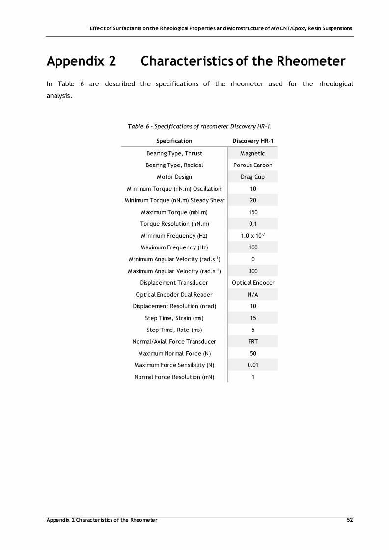
Effect of Surfactants on the Rheological Properties and Microstructure of MWCNT/Epoxy Resin Suspensions
Appendix 2 Characteristics of the Rheometer 52
Appendix 2 Characteristics of the Rheometer
In Table 6 are described the specifications of the rheometer used for the rheological
analysis.
Table 6 - Specifications of rheometer Discovery HR-1.
Specification Discovery HR-1
Bearing Type, Thrust Magnetic
Bearing Type, Radical Porous Carbon
Motor Design Drag Cup
Minimum Torque (nN.m) Oscillation 10
Minimum Torque (nN.m) Steady Shear 20
Maximum Torque (mN.m) 150
Torque Resolution (nN.m) 0,1
Minimum Frequency (Hz) 1.0 x 10⁻⁷
Maximum Frequency (Hz) 100
Minimum Angular Velocity (rad.s-1) 0
Maximum Angular Velocity (rad.s-1) 300
Displacement Transducer Optical Encoder
Optical Encoder Dual Reader N/A
Displacement Resolution (nrad) 10
Step Time, Strain (ms) 15
Step Time, Rate (ms) 5
Normal/Axial Force Transducer FRT
Maximum Normal Force (N) 50
Maximum Force Sensibility (N) 0.01
Normal Force Resolution (mN) 1

Effect of Surfactants on the Rheological Properties and Microstructure of MWCNT/Epoxy Resin Suspensions
Appendix 3 Optical Microscopy Analysis 53
Appendix 3 Optical Microscopy Analysis
The number of agglomerates and area ratio, used as dispersion indicators, are normalized by
equations (7) and (8).
𝑁𝑢𝑚𝑏𝑒𝑟 𝑜𝑓 𝐴𝑔𝑔𝑙𝑜𝑚𝑒𝑟𝑎𝑡𝑒𝑠 (𝑝𝑒𝑟 𝑚𝑚2) =𝐴𝑣𝑒𝑟𝑎𝑔𝑒 𝑁𝑢𝑚𝑏𝑒𝑟 𝑜𝑓 𝐴𝑔𝑔𝑙𝑜𝑚𝑒𝑟𝑎𝑡𝑒𝑠
𝑂𝑏𝑠𝑒𝑟𝑣𝑎𝑡𝑖𝑜𝑛 𝐴𝑟𝑒𝑎×106 (7)
𝐴𝑟𝑒𝑎 𝑅𝑎𝑡𝑖𝑜 (%) =𝐴𝑣𝑒𝑟𝑎𝑔𝑒 𝑇𝑜𝑡𝑎𝑙 𝐴𝑟𝑒𝑎 𝑜𝑓 𝐴𝑔𝑔𝑙𝑜𝑚𝑒𝑟𝑎𝑡𝑒𝑠
𝑂𝑏𝑠𝑒𝑟𝑣𝑎𝑡𝑖𝑜𝑛 𝐴𝑟𝑒𝑎×100 (8)
Depending on the objective, 20x or 40x, the observation area was 3.48×105 µm2 or
8.62×104 µm2.

Effect of Surfactants on the Rheological Properties and Microstructure of MWCNT/Epoxy Resin Suspensions
Appendix 4 Data Summary 54
Appendix 4 Data Summary
In Table 7 is presented a summary of the data obtained.
Table 7 - Summary of the results obtained.
Suspension Type Composition Viscosity
(�̇� = 1 s-1)
Yield Stress Thixotropic Index Critical Angular Frequency Electrical Conductivity Number of Agglomerates Area Ratio
% Pa.s Pa MPa.s-1 rad.s-1 S.m-1 Per mm2 %
Epoxy/MWCNT
0 10.4 52.4 0.960 - 1.16E-11 - -
0.06 10.3 43.6 1.0 0.092 2.51E-06 - -
0.125 11.4 59.2 0.940 0.019 8.57E-07 - -
0.25 14.5 67.3 0.942 0.015 2.05E-04 - -
0.375 25.0 91.0 1.07 0.030 8.81E-04 47 ± 33 0.04 ± 0.007
0.5 36.5 109.4 1.06 0.058 5.65E-04 67 ± 57 0.07 ± 0.02
0.75 65.6 118.7 1.18 0.230 2.15E-04 - -
1.0 114.5 174.1 1.15 4.13 6.90E-04 45 ± 20 0.21 ± 0.08
Epoxy/MWCNT/Triton X-100
0.00012 (1 CMC) 122.1 154.0 0.864 4.05 1.00E-02 - -
0.0029 (20 CMC) 119.3 145.2 1.01 6.07 1.01E-03 - -
1.0 117.9 147.0 0.776 7.58 6.28E-03 122 ± 41 0.06 ± 0.01
1.5 107.6 132.3 0.980 3.54 - - -
2.0 107.4 137.3 1.07 3.91 2.55E-09 133 ± 42 0.06 ± 0.02
5.0 94.1 109.9 0.865 11.0 - - -
10.0 76.6 80.4 0.625 14.2 - - -

Effect of Surfactants on the Rheological Properties and Microstructure of MWCNT/Epoxy Resin Suspensions
Appendix 4 Data Summary 55
(Continuation of Table 7)
Suspension Type Composition Viscosity
(�̇� = 1 s-1)
Yield Stress Thixotropic Index Critical Angular Frequency Electrical Conductivity Number of Agglomerates Area Ratio
% Pa.s Pa MPa.s-1 rad.s-1 S.m-1 Per mm2 %
Epoxy/MWCNT/SDBS
0.00057 (1 CMC) 124.3 165.3 1.16 5.45 4.33E-03 - -
1.0 (20 CMC) 122.7 162.6 1.13 9.79 5.46E-03 60 ± 25 0.04 ± 0.006
1.5 145.2 171.1 0.821 27.1 - - -
2.0 138.5 172.4 0.873 18.7 3.53E-05 138 ± 63 0.07 ± 0.02
5.0 156.6 207.4 1.32 27.3 - - -
10.0 221.0 300.9 1.77 33.8 - - -
Epoxy/MWCNT/PPGMBE
1.0 113.4 143.1 1.04 11.0 - - -
2.0 112.4 127.3 0.874 28.7 - - -
10.0 74.1 78.7 0.602 23.7 - - -