Effect of Steel Shearhead on Behaviour of Eccentrically … · Effect of Steel Shearhead on...
14
Journal of Engineering and Development, Vol. 17, No.1, Mar. 2013, ISSN 1813‐ 7822 Effect of Steel Shearhead on Behaviour of Eccentrically Loaded Reinforced Concrete Flat Plate Asst. Prof. Dr. Jamal Saeed Abd Al-Amier Asst. Prof. Dr. Mohammed M. Rasheed Al-Mustansiriya University, Al-Mustansiriya University College of Engineering, College of Engineering, Civil Department Civil Department Rwayda Khdier Salman Al-Mustansiriya University, College of Engineering Civil Department Abstract The aim of this study is to investigate the punching shear of reinforced concrete slabs (with steel shearhead as shear reinforcement) under eccentric load; this simulates the effect of unbalance moment on slab column connection with shearhead. The research includes testing nine specimens with dimensions (1000 x 1000 x 80 mm) divided into three groups of specimens according to the percent of shearheads. Variables of this study are the number of stiffeners of the shearheads and the amount of eccentricity. The results show that the deformations and strength characteristic of the slab are affected by. القص تسليح تأثيرذي الفوطات الب تصرف على المستويهمسلحة اللخرسانية امركزية الحمال احت تصة الخ الھدف من الب ھذامسلحة اللخرسانية اطاتلب للثاقب ا القص دراسة ھو حث) القصذ فو من رؤوسالحاوية ا قص كتسليح المطمور( تاثير الدراسة ھذه تمثل حيثمركزي حملحت ت على متوازن الغير العزم بينتصال ا منطقةلوح ال و العمود بوجودذي الفو القص تسليح. تسع فحص البحث يتضمن ة بابع نماذج اد) 1000 x 1000 x 80 م م( ذي الفو القص تسلحجود و حسب مجاميعث ث الىقسمه م. تسليح داخل التقويه الواحد عد ھي الدراسة ھذهغيرات متذي الفو القصمركزية اللمسافة ا و. لنتائج ا اوضحت مقامة و التشوه على واضح تأثير لھمارين المتغي ھذين انمسلحه اللخرسانة اطات ب. 1. Introduction Flat plate structure has an advantage over other slab system because of the significant saving in construction work and aesthetically pleasing appearance. In addition, the elimination of beams and girders reduce the over all floor depth of multi-story buildings, thus creating additional floor space for a given building height. For this reason, flat plates are widely used for multi-story structures [1] . Concert flat plates are subjected to large bending moment and shearing force at their connections with columns. In flexure, reinforced concrete slabs exhibit a great deal of ductility; extensive deformations occur before their ultimate strength is reached. Design codes 14
Transcript of Effect of Steel Shearhead on Behaviour of Eccentrically … · Effect of Steel Shearhead on...

Journal of Engineering and Development, Vol. 17, No.1, Mar. 2013, ISSN 1813‐ 7822
Effect of Steel Shearhead on Behaviour of Eccentrically
Loaded Reinforced Concrete Flat Plate
Asst. Prof. Dr. Jamal Saeed Abd Al-Amier Asst. Prof. Dr. Mohammed M. Rasheed
Al-Mustansiriya University, Al-Mustansiriya University
College of Engineering, College of Engineering,
Civil Department Civil Department
Rwayda Khdier Salman Al-Mustansiriya University, College of Engineering Civil Department
Abstract The aim of this study is to investigate the punching shear of reinforced concrete
slabs (with steel shearhead as shear reinforcement) under eccentric load; this simulates the
effect of unbalance moment on slab column connection with shearhead. The research
includes testing nine specimens with dimensions (1000 x 1000 x 80 mm) divided into three
groups of specimens according to the percent of shearheads. Variables of this study are the
number of stiffeners of the shearheads and the amount of eccentricity. The results show
that the deformations and strength characteristic of the slab are affected by.
الخرسانية المسلحة المستويه على تصرف البالطات الفوالذيتأثير تسليح القص
تحت األحمال الالمركزية الخالصةالحاوية رؤوسا من فوالذ القص (حث ھو دراسة القص الثاقب للبالطات الخرسانية المسلحة ھذا الب منالھدف
منطقة االتصال بين العزم الغير متوازن على تحت حمل المركزي حيث تمثل ھذه الدراسة تاثير ) المطمور كتسليح قص) مم x 1000 x 80 1000(اد نماذج بابعةيتضمن البحث فحص تسع. تسليح القص الفوالذي بوجودالعمود و اللوح
متغيرات ھذه الدراسة ھي عدد الواح التقويه داخل تسليح . مقسمه الى ثالث مجاميع حسب وجود تسلح القص الفوالذي ان ھذين المتغيرين لھما تأثير واضح على التشوه و مقامة اوضحت النتائج .و المسافة الالمركزيةالقص الفوالذي
.بالطات الخرسانة المسلحه
1. Introduction Flat plate structure has an advantage over other slab system because of the significant
saving in construction work and aesthetically pleasing appearance. In addition, the
elimination of beams and girders reduce the over all floor depth of multi-story buildings, thus
creating additional floor space for a given building height. For this reason, flat plates are
widely used for multi-story structures [1].
Concert flat plates are subjected to large bending moment and shearing force at their
connections with columns. In flexure, reinforced concrete slabs exhibit a great deal of
ductility; extensive deformations occur before their ultimate strength is reached. Design codes
14

Journal of Engineering and Development, Vol. 17, No.1, Mar. 2013, ISSN 1813‐ 7822
place increasing reliance on this ductile behavior which enables slab system to redistribute
moments. Complete redistribution of bending moment can generally be achieved [2].
Shearhead is a structural member embedded at the slab-column junction. In the flat plate
structure, column support leads to punching shear stresses in the slab. The concrete will
provide a certain level of shear resistance around the columns, but this may need to be
supplemented by punching shear reinforcement arranged on concentric perimeters [3].
The main advantage of shearheads is that they serve to spread the load of the floor on the
respective columns and thereby reduce the effect of the vertical forces; i.e., push the critical
section for shear farther out from the columns, thus giving a large perimeter around the
column to resist the punching shear [3].
2. Materials Concrete compositions, reinforcing steel bars and steel shearhead consist from
steel C channel sections and Tee sections, were tested in the laboratory and showed
good agreement with specifications:
- Water: tap water used.
- Cement: Ordinary Portland cement was used. The physical analysis and
chemical test results conform to the Iraqi specification No. 5/1984 [4].
- Fine Aggregate (Sand): The fine aggregate has 4.75mm maximum size with
rounded-shape particles and smooth texture. The physical analysis test results
are within the limits of Iraqi Specification No. 45/1984 [5].
- Coarse Aggregate (Gravel): The gravel has maximum size of 5mm. The
physical analysis test results are within the limits of Iraqi Specification No.
45/1984 [5].
- Steel Reinforcement: The steel reinforcement used to reinforce the concrete
slab is deformed mesh bars 6 mm diameter and 75mm spacing. Columns
reinforcement was 7 bars 12 mm diameter for all slabs.
- Steel Shearheads: consist from steel C Channel sections and Tee sections
plate (1).
Plate (1) Shearhead Reinforcement
15
Journal of Engineering and Development, Vol. 17, No.1, Mar. 2013, ISSN 1813‐ 7822
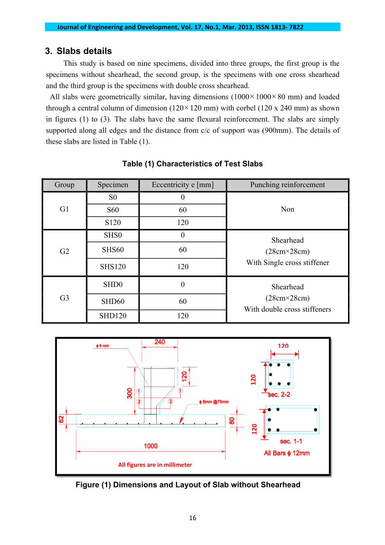
3. Slabs details This study is based on nine specimens, divided into three groups, the first group is the
specimens without shearhead, the second group, is the specimens with one cross shearhead
and the third group is the specimens with double cross shearhead.
All slabs were geometrically similar, having dimensions (1000×1000×80 mm) and loaded
through a central column of dimension (120×120 mm) with corbel (120 x 240 mm) as shown
in figures (1) to (3). The slabs have the same flexural reinforcement. The slabs are simply
supported along all edges and the distance from c/c of support was (900mm). The details of
these slabs are listed in Table (1).
Table (1) Characteristics of Test Slabs
Group Specimen Eccentricity e [mm] Punching reinforcement
S0 0
S60 60 G1
S120 120
Non
SHS0 0
SHS60 60 G2
SHS120 120
Shearhead
(28cm×28cm)
With Single cross stiffener
SHD0 0
SHD60 60 G3
SHD120 120
Shearhead
(28cm×28cm)
With double cross stiffeners
120
120
120
All figures are in millimeter
Figure (1) Dimensions and Layout of Slab without Shearhead
16

Journal of Engineering and Development, Vol. 17, No.1, Mar. 2013, ISSN 1813‐ 7822
All figures are in millimeter
Figure (2) Dimensions and Layout of Slab with Shearhead of Single Cross
Stiffener
All figures are in millimeter
Figure (3) Dimensions and Layout of Slab with Shearhead of Double Cross
Stiffeners
17

Journal of Engineering and Development, Vol. 17, No.1, Mar. 2013, ISSN 1813‐ 7822
4. Concrete Mix, Casting and Curing The following steps are followed before mixing;
1. The fine aggregate is washed and dried to remove any clay particles.
2. The coarse aggregate is sieved on (10mm) sieve size to remove the large size
aggregate particles. Then, the aggregate is also washed and dried.
3. Preparing the weights.
Mixing method is important to obtain the required workability and homogeneity. A
(0.125m3) drum mixer is used. Coarse and fine aggregates are poured into the mixer, and
mixed together. The cement is then added to the mixer, and then water is added gradually to
the mix. The total mixing time is (6-8 min).
After (24) hours, the control specimens were stripped from the moulds and cured (kept)
in water bath for (28) days with almost constant laboratory temperature. Before (24) hours
from test date, they were taken out of the water bath and then tested in accordance with the
standard specifications after painted by using white washer.
5. Testing Machine The machine which was used in the tests is a universal hydraulic machine with (300 ton)
capacity available in the structural engineering laboratory, in the College of Engineering, Al-
Mustansiriya University. The loading arrangement with loading frame is shown in plate (2).
Plate (2) Testing Machine with Loading Frame
5.1. Loading Caps (Eccentricity Apparatus) A new steel loading cap was designed to provide eccentric loading. The loading cap has a
rectangular section (120×240mm) and thickness 20mm and can give three values of
eccentricity. The eccentric load was exerted on the loading cap via a wedge plate that was
18

Journal of Engineering and Development, Vol. 17, No.1, Mar. 2013, ISSN 1813‐ 7822
positioned into the 0mm, 60mm or 120mm grooves, respectively. It is manufactured in the
structural Laboratory at the University of AL-Mustansiriyha from high strength steel. The
method of loading is shown in plate (3)
a- Axial Loading b- Eccentricity at 60mm
c- Eccentric at 120mm
Plate (3) Loading Caps
6. Discussion and Results 6.1. Crack Pattern Test results show that the punching crack tends to be at one side of slab with the increase of
eccentricity of loading form (0 to 120 mm) for slabs with or without shear reinforcement, due to
presence of unbalance bending moment Plates (4) to (12) show tension face for all tested slabs.
In general, the failure pattern for all specimens shows that shearheads are sufficient stiff to push
the critical punching shear perimeter outside the shearhead.
Plate (4) Tension Face for Slab S0 Plate (5) Tension Face for Slab S60
19

Journal of Engineering and Development, Vol. 17, No.1, Mar. 2013, ISSN 1813‐ 7822
Plate (6) Tension Face for Slab S120 Plate (7) Tension Face for Slab SHS0
Plate (8) Tension Face for Slab SHS60 Plate (9) Tension Face for Slab HS120
Plate (10) Tension Face for Slab SHD0 Plat (11) Tension Face for Slab SHD60
20

Journal of Engineering and Development, Vol. 17, No.1, Mar. 2013, ISSN 1813‐ 7822
Plate (12) Tension Face for Slab SHD120
6.2. Ultimate Load Capacity The primary aim of this study is to determine the ultimate load capacity of specimens
reinforced for punching shear caused by eccentric loading and shearheads reinforcement then
compare it with the reference specimen (without punching shear reinforcement). The observed
failure loads of the tested slabs are shown in Table (2).
Table (2) Cracking and Ultimate Loads
Group
Specimen
Ultimate
Load
(Pult) (kN)
Ultimate
unbalance
moment
(Mult)
(KN.m)
% Decrease in
Ultimate Load
Relative to zero
eccentricity
specimen
% Increase in
Ultimate Load
Relative to G1
Type of Failure
S0 74 0 --- --- Punching
S60 71.5 4.29 3.4 --- Punching G1
S120 65.75 7.89 11.1 --- Incomplete punching
SHS0 84 0 --- 13.5 Punching
SHS60 77 4.62 8.3 7.8 Incomplete punching
G2
SHS120 72.5 8.7 13.7 10.3 Incomplete punching
SHD0 96.5 0 --- 30.4 Punching
SHD60 89 5.34 7.8 24.5 Punching
G3
SHD120 81.75 9.81 15.3 24.7 Incomplete punching
Test results are listed below: Group G1: (Specimens without shear reinforcement)
In (S0), the punching shear failure occurs at the higher loads than the other slabs
(with eccentricity). The test results show that the slabs (S60 and S120) give decrease
in strength over the reference slab (S0) by about (3.4 and 11.1%) respectively.
21

Journal of Engineering and Development, Vol. 17, No.1, Mar. 2013, ISSN 1813‐ 7822
Group G2: (Specimens with shearhead reinforcement having single stiffener)�
In (SHS0), the punching shear failure occurs at the higher loads than the other slabs
(with eccentricity). The test results show that the slabs (SHS60 and SHS120) give
decrease in strength over the reference slab (SHS0) by about (8.3 and 13.7 %)
respectively.
Group G3: (Specimens with shearhead reinforcement having double stiffeners) �
In (SHD0), the punching shear failure occurs at the higher loads than the other slabs
(with eccentricity). The test results show that the slabs (SHD60 and SHD120) give
decrease in strength over the reference slab (SHD0) by about (7.8 and 15.3 %),
respectively.
In general:
1. The increase of ultimate load in ( G2 and G3 ) over ( G1 ), by adding shearhead
reinforcement can be explained by the increase in critical shear perimeter of punching
shear in slab, the ratio of increasing is (13.5 and 30.4 %) for slabs (SHS0 and SHD0)
respectively.
2. The effect of the shearhead on slabs with eccentricity (S60, SHS60, SHD60, S120,
SHS120 and SHD120) give lower strength ratio, as compared with reference specimen
(S0, SHS0 and SHD0) because of the eccentric loading that causes unbalance bending
moment .
3. Slabs with shearhead reinforcement and eccentrically load gives higher ultimate load
capacity than those without shear reinforcement by (7.8, 10.3, 24.5 and 24.7) for slabs
(SHS60, SHS120, SHD60 and SHD120).
4. Using shearheads with double cross stiffeners give more ultimate load capacity than
single cross stiffener cause the load will distribute on more steel area.
5. The maximum increase in the ultimate strength of (SHD0) is about (30.4%) as
compared with (S0).
6. The eccentricity in all cases decreases the ultimate load as shown in Figure (4).
6.3. Load - Central Deflection Figures (5) through (10) show the load- central deflection curves for tested slab.
They show a linear relationship up to the first crack but after which, the deflection increases
until failure associated with an increase in the number of cracks.
The test results show that:
1. The increases of eccentricity decrease the central deflection for all slabs with or
without shearheads.
2. The presences of shearhead increase the deflection as function of increasing in
ultimate load capacity.
22

Journal of Engineering and Development, Vol. 17, No.1, Mar. 2013, ISSN 1813‐ 7822
Figure (4) Decreases in Ultimate Load with Increase of Eccentricity
Figure (5) Load-central Deflection Curve for G1
Figure (6) Load-central Deflection Curve for G2
23

Journal of Engineering and Development, Vol. 17, No.1, Mar. 2013, ISSN 1813‐ 7822
Figure (7) Load-central Deflection Curve for G3
Figure (8) Load-central Deflection Curve for e = 0
Figure (9) Load-central Deflection Curve for e = 60 mm
Figure (10) Load-central Deflection Curve for e = 120 mm
24
Journal of Engineering and Development, Vol. 17, No.1, Mar. 2013, ISSN 1813‐ 7822
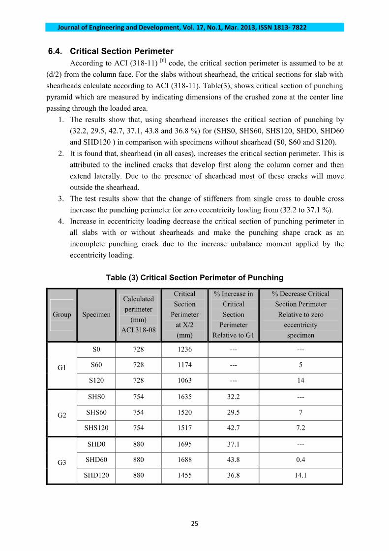
6.4. Critical Section Perimeter According to ACI (318-11) [6] code, the critical section perimeter is assumed to be at
(d/2) from the column face. For the slabs without shearhead, the critical sections for slab with
shearheads calculate according to ACI (318-11). Table(3), shows critical section of punching
pyramid which are measured by indicating dimensions of the crushed zone at the center line
passing through the loaded area.
1. The results show that, using shearhead increases the critical section of punching by
(32.2, 29.5, 42.7, 37.1, 43.8 and 36.8 %) for (SHS0, SHS60, SHS120, SHD0, SHD60
and SHD120 ) in comparison with specimens without shearhead (S0, S60 and S120).
2. It is found that, shearhead (in all cases), increases the critical section perimeter. This is
attributed to the inclined cracks that develop first along the column corner and then
extend laterally. Due to the presence of shearhead most of these cracks will move
outside the shearhead.
3. The test results show that the change of stiffeners from single cross to double cross
increase the punching perimeter for zero eccentricity loading from (32.2 to 37.1 %).
4. Increase in eccentricity loading decrease the critical section of punching perimeter in
all slabs with or without shearheads and make the punching shape crack as an
incomplete punching crack due to the increase unbalance moment applied by the
eccentricity loading.
Table (3) Critical Section Perimeter of Punching
Group
Specimen
Calculated
perimeter
(mm)
ACI 318-08
Critical
Section
Perimeter
at X/2
(mm)
% Increase in
Critical
Section
Perimeter
Relative to G1
% Decrease Critical
Section Perimeter
Relative to zero
eccentricity
specimen
S0 728 1236 --- ---
S60 728 1174 --- 5
G1
S120 728 1063 --- 14
SHS0 754 1635 32.2 ---
SHS60 754 1520 29.5 7
G2
SHS120 754 1517 42.7 7.2
SHD0 880 1695 37.1 ---
SHD60 880 1688 43.8 0.4
G3
SHD120 880 1455 36.8 14.1
25

Journal of Engineering and Development, Vol. 17, No.1, Mar. 2013, ISSN 1813‐ 7822
6.5. Failure Angle Figure (11) shows the location of failure angles of the punching pyramid, the angles are
measured by indicating the dimensions of crushed zone at the center line passing through the
loaded area. Table (4) shows the failure angle, where Y represents the distance between the
failure perimeter to the column face and the subscript (N, S, E & W) define the direction.
The results show that a shearhead decreases the failure angle in comparison to the
slabs without shearhead.
Increasing the stiffeners of shearhead increase the failure angle in north direction
for slab with or without eccentricity.
Eccentric loading decrease the failure angle in slabs with shearheads
reinforcement and.
The increasing of eccentricity gives no failure angle in the opposite side of
eccentricity, and cause a collapse at only one side (at north direction).
Table (4) Failure Angle
Group Specimen YN
(mm)
YS
(mm)
YW
(mm)
YE
(mm) Ø N̊ Ø ̊ S Ø ̊ W Ø ̊ E
S0 260.02 285.4 220.92 290.18 17.10 15.70 19.90 15.40
S60 217.05 228.74 193.43 292.63 20.20 19.30 22.50 15.30 G1
S120 201.09 0 279.1 230.30 21.70 --- 15.99 19.20
SHS0 335.75 271.64 286 270.4 13.40 16.41 15.60 16.50
SHS60 360.57 0 383.2 360.1 12.50 --- 11.79 12.53
G2
SHS120 302.65 0 436.6 358.4 14.80 --- 10.38 12.58
SHD0 251.1 279.05 352.7 350.06 17.67 16.00 12.78 12.87
SHD60 271.52 303.4 344.9 321 16.42 14.77 13.06 13.99
G3
SHD120 305.43 0 346.6 321.6 14.68 --- 13.00 13.97
a. N-S direction b. E-W direction
Figure (11) Location of failure angles
26

Journal of Engineering and Development, Vol. 17, No.1, Mar. 2013, ISSN 1813‐ 7822
27
7. Conclusions According to the test program carried out in the present study, the following
conclusions can be drawn:-
1. The punching shear failure in slabs with eccentricity loading is gradual and incomplete
in most of slabs, while it is a sudden punching shear failure in slabs with no eccentricity
loading.
2. The eccentricity loading decreases the ultimate load.
3. Slabs fail in punching shear have no visible cracks on the compression surface and the
punching line occurred directly at the vicinity of the column faces.
4. The presence of shearhead reinforcement in a reinforced concrete slab increases the
punching shear strength of the slab.
References [1] Al-Maiaahei, A., "Experimental Study of Flat Plate Construction with Special
Embedded Shearhead", M.Sc. Thesis, Civil Engineering Department, Al-Mustansiriya
University, 2006.
[2] Park H. G., Choi K. K. and Chungc L.," Strain-Based Strength Model for direct
Punching Shear of Interior Slab–Column Connections", Engineering Structures Journal
,Vol 33, No. 3, January 2011, PP. 1062–1073.
[3] Ghali, A., "An Efficient Solution to Punching of Slabs", Concrete International, Vol.11,
No.6, June 1989, PP. 50-54.
[4] Iraqi Specification No. 45,, "Portland Cement", Baghdad, 1984.
[5] Iraqi Specification No. 45, "Natural Sources for Gravel that is Used in Concrete and
Construction", Baghdad, 1984.
[6] ACI Committee 318, ''Building Code Requirements for Structural Concrete (ACI 318M‐11)
and Commentary (ACI 318R‐11)'', American Concrete Instate, Farmington Hill, MI.