Effect of Process Variations - SMTnet
7
1 / 7 Effect of Process Variations on Solder Joint Reliability for Nickel-based Surface Finishes Hugh Roberts Atotech USA Inc., Rock Hill, SC, USA Sven Lamprecht, Gustavo Ramos and Christian Sebald Atotech Deutschland GmbH, Berlin, Germany ABSTRACT Following the adoption of recent Pb-free requirements, PWB and IC substrate fabricators, assemblers and OEMs continue to search for a surface finish that will minimize solder joint reliability concerns. Historically, electroless nickel / immersion gold (ENIG) has pro- vided a reliable finish for soldering applications. The nickel layer provides the added benefit of serving as a barrier to minimize copper dissolution during the sol- dering operation. Preservation of the underlying cop- per will become increasingly important as circuit fea- tures continue to shrink and signal integrity becomes a more critical issue. However, ENIG is not trouble-free; as the immersion gold reaction can often excessively corrode the nickel layer, leading to the occurrence of “black pad” and tendencies toward brittle failure in sol- der joints. As an alternative to ENIG, an electroless palladium layer over the nickel (NiPd) should provide a solderable surface while minimizing impact to the nickel deposit. By eliminating the corrosive immersion gold reaction, the resultant intermetallics should con- tribute to improved solder joint integrity, even after multiple Pb-free reflow operations. This paper summarizes the results of recent investiga- tions to examine the effect of electroless nickel process variations with respect to Pb-free (Sn-3.0Ag- 0.5Cu) solder connections. These investigations in- cluded both ENIG and NiPd as surface finishes in- tended for second level interconnects in BGA applica- tions. Process variations that are suspected to weaken solder joint reliability, including treatment time and pH, were used to achieve differences in nickel layer com- position. Immersion gold deposits were also varied, but were directly dependent upon the plated nickel characteristics. In contrast to gold, different electroless palladium thicknesses were independently achieved by treatment time adjustments. Results of investigations include: (1) Cold ball pull testing to evaluate solder joint integrity, (2) SEM examinations of the underlying nickel surface and (3) IMC examinations to quantify nickel thickness degra- dation after multiple solder reflow cycles. The paper discusses the relatively simple approach that, if proven effective in large-scale fabrication, may significantly reduce or eliminate many of the well-known reliability concerns associated with nickel-based intermetallics in a Pb-free assembly environment. BACKGROUND As a surface finish for BGA applications, electroless nickel / immersion gold (ENIG) has been traditionally accepted for use on both IC substrates and PWBs. The principal benefit of ENIG as a surface finish re- lates to the role of the nickel layer, which functions as a barrier to limit the dissolution of underlying copper into the solder joint. With continued miniaturization of circuit features, coupled with the need for maintaining signal attenuation, copper dissolution into the solder joint is a critical issue and a barrier to such dissolution is a key objective. Solder joint formation of ENIG sur- face finishes occurs by dissolution of gold into the sol- der, forming an IMC between the nickel and tin. How- ever, solder joints comprised of nickel-tin intermetallic compounds (IMC) are generally regarded as more prone to brittle fracture in comparison to copper-tin IMCs. Therefore, it is imperative to control formation of the nickel/tin IMC to produce the desired ductile solder joint. With ENIG, if not properly controlled, the immersion gold step can significantly corrode the nickel layer. In the worst cases, such corrosion can result in the so- called “black pad” effect. Such attack of the nickel layer can lead to increased occurrence of brittle frac- ture and serious solder joint reliability concerns as a result. Considerable effort has been devoted to limiting or preventing the occurrence of such nickel attack. One such technique promotes the use of higher phos- phorous concentrations in the nickel deposit, making it more resistant to the corrosive nature of the immersion gold solution and resulting in a denser and more evenly formed nickel-tin IMC [1] Another method for controlling nickel corrosion in- volves the use of a thin layer of palladium, deposited autocatalytically on the nickel surface, thus protecting it during the immersion gold reaction. This electroless nickel / electroless palladium / immersion gold (Ni/Pd/Au) surface finish was actually introduced in the mid-1990s. However, with the widespread adoption of
Transcript of Effect of Process Variations - SMTnet

1 / 7
Effect of Process Variations on Solder Joint Reliability for Nickel-based Surface Finishes
Hugh Roberts
Atotech USA Inc., Rock Hill, SC, USA
Sven Lamprecht, Gustavo Ramos and Christian Sebald
Atotech Deutschland GmbH, Berlin, Germany
ABSTRACT Following the adoption of recent Pb-free requirements, PWB and IC substrate fabricators, assemblers and OEMs continue to search for a surface finish that will minimize solder joint reliability concerns. Historically, electroless nickel / immersion gold (ENIG) has pro-vided a reliable finish for soldering applications. The nickel layer provides the added benefit of serving as a barrier to minimize copper dissolution during the sol-dering operation. Preservation of the underlying cop-per will become increasingly important as circuit fea-tures continue to shrink and signal integrity becomes a more critical issue. However, ENIG is not trouble-free; as the immersion gold reaction can often excessively corrode the nickel layer, leading to the occurrence of “black pad” and tendencies toward brittle failure in sol-der joints. As an alternative to ENIG, an electroless palladium layer over the nickel (NiPd) should provide a solderable surface while minimizing impact to the nickel deposit. By eliminating the corrosive immersion gold reaction, the resultant intermetallics should con-tribute to improved solder joint integrity, even after multiple Pb-free reflow operations. This paper summarizes the results of recent investiga-tions to examine the effect of electroless nickel process variations with respect to Pb-free (Sn-3.0Ag-0.5Cu) solder connections. These investigations in-cluded both ENIG and NiPd as surface finishes in-tended for second level interconnects in BGA applica-tions. Process variations that are suspected to weaken solder joint reliability, including treatment time and pH, were used to achieve differences in nickel layer com-position. Immersion gold deposits were also varied, but were directly dependent upon the plated nickel characteristics. In contrast to gold, different electroless palladium thicknesses were independently achieved by treatment time adjustments. Results of investigations include: (1) Cold ball pull testing to evaluate solder joint integrity, (2) SEM examinations of the underlying nickel surface and (3) IMC examinations to quantify nickel thickness degra-dation after multiple solder reflow cycles. The paper discusses the relatively simple approach that, if proven effective in large-scale fabrication, may significantly
reduce or eliminate many of the well-known reliability concerns associated with nickel-based intermetallics in a Pb-free assembly environment. BACKGROUND As a surface finish for BGA applications, electroless nickel / immersion gold (ENIG) has been traditionally accepted for use on both IC substrates and PWBs. The principal benefit of ENIG as a surface finish re-lates to the role of the nickel layer, which functions as a barrier to limit the dissolution of underlying copper into the solder joint. With continued miniaturization of circuit features, coupled with the need for maintaining signal attenuation, copper dissolution into the solder joint is a critical issue and a barrier to such dissolution is a key objective. Solder joint formation of ENIG sur-face finishes occurs by dissolution of gold into the sol-der, forming an IMC between the nickel and tin. How-ever, solder joints comprised of nickel-tin intermetallic compounds (IMC) are generally regarded as more prone to brittle fracture in comparison to copper-tin IMCs. Therefore, it is imperative to control formation of the nickel/tin IMC to produce the desired ductile solder joint. With ENIG, if not properly controlled, the immersion gold step can significantly corrode the nickel layer. In the worst cases, such corrosion can result in the so-called “black pad” effect. Such attack of the nickel layer can lead to increased occurrence of brittle frac-ture and serious solder joint reliability concerns as a result. Considerable effort has been devoted to limiting or preventing the occurrence of such nickel attack. One such technique promotes the use of higher phos-phorous concentrations in the nickel deposit, making it more resistant to the corrosive nature of the immersion gold solution and resulting in a denser and more evenly formed nickel-tin IMC [ 1] Another method for controlling nickel corrosion in-volves the use of a thin layer of palladium, deposited autocatalytically on the nickel surface, thus protecting it during the immersion gold reaction. This electroless nickel / electroless palladium / immersion gold (Ni/Pd/Au) surface finish was actually introduced in the mid-1990s. However, with the widespread adoption of

2 / 7
Pb-free soldering, this finish has again demonstrated improved performance in comparison to ENIG and has gained considerable attention. The suitability of the Ni/Pd/Au finish (employing a pure palladium deposit) for both wire bonding and soldering has been previously reported 2, 3]. More recently, the findings of a major design of experiment (DoE) that compared the performance of several ENIG and Ni/Pd/Au finishes using different solder ball pull and shear investigations were reported [ 4]. The results of those investigations indicated that the Ni/Pd/Au process provides improved bonding results for meeting the more demanding BGA soldering requirements for the Sn-Ag-Cu alloy compositions. In light of the renewed interest in nickel-based surface finishes, investigations were initiated to determine if a more simplified process comprised of electroless nickel / electroless palladium (Ni/Pd) could provide equivalent benefits at a lower cost. DESCRIPTION OF INVESTIGATIONS As part of a more comprehensive DoE, investigations were conducted to compare the performance of two different surface finishes: ENIG and Ni/Pd. The cold ball pull test was used as the primary method to evaluate the solder joint reliability of these two nickel-based surface finishes. Test Vehicle Figure 1 shows an example of the BGA test vehicle used for these investigations. Also shown are the lo-cations of the 30 solder balls tested. As shown, four balls are located at each of the remote corners of the grid array and the remaining 14 balls are located diagonally across the center of the array.
Fig. 1 BGA test vehicle for cold ball pull testing showing lo-cation of solder balls tested and detail of four-point anchor design (under solder mask). The objective of the DoE was to specifically evaluate deposit characteristics and solder joint reliability in re-lation to variations in surface finish. Build-up material
used for IC substrate fabrication cannot typically pro-vide sufficient adhesive strength to withstand the forces of the cold ball pull testing. Most failures occur as a result of the loss of adhesion between the copper pad and the underlying dielectric and the bond at the surface finish is not adequately tested. Therefore, it is important to note that the test vehicle used for these investigations, including both the base material and pad design, was intentionally developed to be conducive to interfacial fractures between solder and pad finish (or failure within the bulk solder). FR4 was used as the test vehicle dielectric because of its in-herently higher adhesive strength (50-70% greater than build-up materials). Furthermore, all pads were designed to include a “four-point anchoring” feature. This construction method has been shown to con-sistently promote the occurrence of interfacial failures by firmly securing the test pads to the underlying dielectric material. Surface Finish The test vehicles were fabricated with two different surface finishes, ENIG and Ni/Pd. In the case of ENIG, three different surface thickness variations of elec-troless nickel were used; depositing 4.0 µm, 5.0 µm and 6.0 µm of nickel, while maintaining a relatively constant 0.09-µm immersion gold thickness. For the Ni/Pd finish, nine different deposit variations were used, with nickel thicknesses of 4.0 µm, 5.0 µm and 6.0 µm in combination with palladium thicknesses of 0.04 µm, 0.10 µm and 0.30 µm. In all cases, the nickel and palladium were both co-deposited with phospho-rus; 8-10 percent phosphorus by weight in the nickel deposit and 4-6 percent by weight in the palladium deposit. The nickel deposit thickness was controlled by adjusting the plating rate of the electroless nickel solution. The thickness of the palladium deposit was adjusted according to treatment time. Table 1 presents a summary of the surface finishes included in these investigations.
Table 1 – Summary of Surface Finish Specifications Surface Finish Ni Pd Au Ni 4.0 / Au 0.09 4.0 µm - 0.09 µm Ni 5.0 / Au 0.09 5.0 µm - 0.09 µm Ni 6.0 / Au 0.09 6.0 µm - 0.09 µm Ni 4.0 / Pd 0.04 4.0 µm 0.04 µm - Ni 5.0 / Pd 0.04 5.0 µm 0.04 µm - Ni 6.0 / Pd 0.04 6.0 µm 0.04 µm - Ni 4.0 / Pd 0.10 4.0µm 0.10µm - Ni 5.0 / Pd 0.10 5.0µm 0.10µm - Ni 6.0 / Pd 0.10 6.0µm 0.10µm - Ni 4.0 / Pd 0.30 4.0µm 0.30µm - Ni 5.0 / Pd 0.30 5.0µm 0.30µm - Ni 6.0 / Pd 0.30 6.0µm 0.30µm - Deposit thickness variations: Ni: ± 5%, Pd: ±10% Au: ±10%

3 / 7
Figure 2 shows a comparison of the ENIG and NiPd finish topographies. In the figure, the ENIG surface is shown after the immersion gold deposit has been stripped. As seen, the NiPd surface is very similar in topography to the underlying nickel of the ENIG.
Fig. 2 Comparison of ENIG after gold stripping (left) and NiPd (right) at 5000x Assembly Parameters The key information regarding assembly of the solder balls to the BGA test vehicle is summarized in Table 2. As noted, a Pb-free Sn-4.0Ag-0.5Cu (SAC405) alloy was used for all investigations. All bond testing was performed within four hours of reflow. Figure 3 shows the solder reflow profile that was used for all investiga-tions.
Fig. 3 Pb-free solder reflow profile Test Procedures - Cold Ball Pull As previously noted, cold ball pull investigations in-cluded the testing of 30 Pb-free solder balls from each test sample. The test samples differed only according to their respective surface finish. Solder balls of 760-µm diameter were mounted on solder resist-defined pads with solder resist openings (SRO) of 650µm.
Cold ball pull testing was performed on the Dage 4000 Multi-Function Bond Tester. The ball pull test mecha-nism and a detailed view of the ball pull device are shown in Figures 4 and 5, respectively. Table 3 presents a summary of the important pa-rameters related to the cold ball pull investigations.
Table 3 – Cold Ball Pull Test Parameters Equipment Dage Series 4000 Ball pull speed 5 mm/sec Solder Ball Diameter 760 µm Solder Resist Opening 650 µm Test Conditions After Pb-free ball attach
After 5 additional Pb-free reflow cycles
Fig. 4 Dage Series 4000 Multi-Purpose Bond Tester
Fig. 5 Detailed view of the solder ball pull device on the Dage Series 4000 Multi-Purpose Bond Tester
Table 2 – Solder Ball Reflow Specifications Solder balls Senju Sn4.0Ag0.5Cu Solder Flux Kester TSF6502 Reflow profile TSF6502 Pb-free linear profile Reflow Atmosphere Nitrogen (< 100 ppm O2 ) Peak temperature 258°C Time to peak 241sec Time above liquidus 57sec

4 / 7
Cold ball pull failures were categorized according to the type and location of failure. The preferred type of failure occurs entirely within the solder ball (Mode 2). A bond failure (Mode 4) is indicative of brittle fracture; although unlike ball shear interfacial fractures, in the case of cold ball pull testing the complete IMC is typi-cally exposed. Pad failure or pad “pull-out” (Mode 1) only indicates that the bond of the solder ball to the pad was stronger than the pad-to-substrate adhesive strength. Ball extrusion (Mode 3) may indicate a problem with the clamping force of the device or that the solder composition is too soft. Figure 6 illustrates the location of the four different fracture modes within the solder ball joint.
Fig. 6 Illustration of cold ball pull failure modes and their location within the solder ball joint TESTING RESULTS Cold ball pull test results are reported and evaluated in terms of both pull strength and failure mode. The graphics legend for qualifying the four types of cold ball pull failures is as follows:
Mode 1: Pad failure (pad pull-out) Mode 2: Solder ball failure Mode 3: Solder ball extrusion Mode 4: Bond failure
Testing Results The results of cold ball pull testing performed on sam-ples following “ball attach” (i.e. prior to any additional reflow cycles) are presented in Table 4. These same pull strength data and results of the failure mode analysis are graphically examined in Figure 7. As shown in the upper part of the figure, there is not a significant difference in the pull strength for the sample group. The ENIG samples did achieve slightly lower average pull strengths and those results also showed a wider variation in comparison to the NiPd results. Generally, the pull strength results for the NiPd sam-ples were very consistent. However, a significant dif-ference exists in terms of fracture mode. Nearly all the ENIG samples exhibited interfacial (brittle) fracture, while the majority of the NiPd samples displayed duc-tile fracture or pad failures. In particular, there is a no-
ticeable trend of increased ductile fractures as the palladium deposit thickness increases.
Table 4 – Cold Ball Pull Strength Test Results - After Ball Attach
Surface Finish Mean
Std Dev Min Max
Ni 4.0 / Au 0.09 3383.9 216.4 2639.
3 3851.8
Ni 5.0 / Au 0.09 3239.3 332.0 2553.
3 3734.8
Ni 6.0 / Au 0.09 3420.7 256.2 2777.
8 3887.3
Ni 4.0 / Pd 0.04 3708.5 108.1 3571.
5 3931.3
Ni 5.0 / Pd 0.04 3644.1 93.3 3492.
1 3823.7
Ni 6.0 / Pd 0.04 3663.1 62.3 3510.
6 3780.1
Ni 4.0 / Pd 0.10 3647.4 76.1 3475.
5 3766.6
Ni 5.0 / Pd 0.10 3638.2 80.7 3496.
9 3809.1
Ni 6.0 / Pd 0.10 3608.5 70.9 3446.
1 3736.2
Ni 4.0 / Pd 0.30 3557.6 138.8 3070.
1 3777.8
Ni 5.0 / Pd 0.30 3584.7 79.6 3397.
9 3700.2
Ni 6.0 / Pd 0.30 3600.6 106.3 3359.
8 3809.8
Fig. 7 Summary of cold ball pull strength and fracture modes by surface finish for samples tested in “After Ball Attach” condition
5 / 7
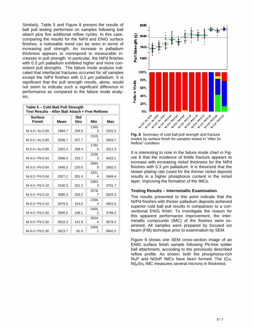
Similarly, Table 5 and Figure 8 present the results of ball pull testing performed on samples following ball attach plus five additional reflow cycles. In this case, comparing the results for the NiPd and ENIG surface finishes, a noticeable trend can be seen in terms of increasing pull strength. An increase in palladium thickness appears to correspond to measurable in-creases in pull strength. In particular, the NiPd finishes with 0.3 µm palladium exhibited higher and more con-sistent pull strengths. The failure mode analysis indi-cated that interfacial fractures occurred for all samples except the NiPd finishes with 0.3 µm palladium. It is significant that the pull strength results, alone, would not seem to indicate such a significant difference in performance as compared to the failure mode analy-sis.
Table 5 – Cold Ball Pull Strength Test Results - After Ball Attach + Five Reflows
Surface Finish Mean
Std Dev Min Max
Ni 4.0 / Au 0.09 1884.7 259.9 1260.
3 2331.5
Ni 5.0 / Au 0.09 2036.7 257.7 1519.
2 2603.7
Ni 6.0 / Au 0.09 2301.4 358.4 1792.
0 3311.3
Ni 4.0 / Pd 0.04 2686.4 315.7 2236.
3 3423.1
Ni 5.0 / Pd 0.04 2495.3 220.6 2094.
9 2952.5
Ni 6.0 / Pd 0.04 2927.2 281.4 2331.
4 3484.4
Ni 4.0 / Pd 0.10 3160.3 301.2 2393.
3 3701.7
Ni 5.0 / Pd 0.10 3085.3 256.2 2578.
7 3525.3
Ni 6.0 / Pd 0.10 3076.5 314.0 2266.
4 3601.6
Ni 4.0 / Pd 0.30 3595.5 108.1 3405.
2 3784.2
Ni 5.0 / Pd 0.30 3516.3 141.9 3024.
4 3679.2
Ni 6.0 / Pd 0.30 3623.7 91.4 3459.
1 3842.5
Fig. 8 Summary of cold ball pull strength and fracture modes by surface finish for samples tested in “After 5x Reflow” condition It is interesting to note in the failure mode chart in Fig-ure 8 that the incidence of brittle fracture appears to increase with increasing nickel thickness for the NiPd finishes with 0.3 µm palladium. It is theorized that the slower plating rate (used for the thinner nickel deposit) results in a higher phosphorus content in the nickel layer, improving the formation of the IMCs. Testing Results – Intermetallic Examination The results presented to this point indicate that the Ni/Pd finishes with thicker palladium deposits achieved superior cold ball pull results in comparison to a con-ventional ENIG finish. To investigate the reason for this apparent performance improvement, the inter-metallic compounds (IMC) of the finishes were ex-amined. All samples were prepared by focused ion beam (FIB) technique prior to examination by SEM. Figure 9 shows one SEM cross-section image of an ENIG surface finish sample following Pb-free solder ball attachment, according to the previously described reflow profile. As shown, both the phosphorus-rich Ni3P and NiSnP IMCs have been formed. The (Cu, Ni)6Sn5 IMC measures several microns in thickness.

6 / 7
Fig. 9 SEM cross-section image at 10,000x (left) of ENIG surface finish after ball attach and detail (right) showing for-mation of Ni3P, NiSnP and (Cu, Ni)6Sn5 IMCs Similarly, Figure 10 shows an SEM cross-section im-age of the ENIG surface finish sample after five addi-tional Pb-free solder reflow cycles. As shown, the Ni3P and NiSnP IMCs have grown as a result of the thermal excursions. Also, the (Cu, Ni)6Sn5 IMC has become significantly larger and more dense.
Fig. 10 SEM cross-section image at 10,000x (left) of ENIG surface finish after 5x reflow cycles and detail (right) showing formation of Ni3P, NiSnP and (Cu, Ni)6Sn5 IMCs By comparison, Figure 11 shows a similar SEM cross-section image of a NiPd surface finish sample fol-lowing Pb-free solder ball attachment. Again, the Ni3P and NiSnP IMCs have been formed and are compa-rable to those in the ENIG sample. In the case of the NiPd sample, there appears to be a more distinct boundary between these two IMCs. More significant, however, is the fact that the (Cu, Ni)6Sn5 IMC is almost not detectable, which is quite different in comparison to the similarly treated ENIG sample.
Fig. 11 SEM cross-section image at 10,000x (left) of NiPd surface finish after ball attach and detail (right) showing for-mation of Ni3P, NiSnP and (Cu, Ni)6Sn5 IMCs
In similar fashion, Figure 12 shows an SEM cross-sec-tion image of the NiPd surface finish sample after the five additional Pb-free solder reflow cycles. As shown, the Ni3P and NiSnP IMCs have grown as a result of the thermal excursions. Again, there appears to be a more distinct boundary and composition between these two IMCs in comparison to the similarly treated ENIG sample. More significantly, the (Cu, Ni)6Sn5 IMC remains extremely thin and does not appear to have grown in comparison to the NiPd sample examined after ball attachment. The palladium layer and/or its contribution to the formed IMCs appear to have limited and nearly prevented any additional growth of the (Cu, Ni)6Sn5 IMC.
Fig. 12 SEM cross-section image at 10,000x (left) of NiPd surface finish after 5x reflow cycles and detail (right) showing formation of Ni3P, NiSnP and (Cu, Ni)6Sn5 IMCs DISCUSSION The investigations presented in this paper are part of a continuing comprehensive DOE focused on enhance-ment of surface finishes for high-density IC substrates (ball-side and C4-side) used in flip chip BGAs applica-tions. In these investigations, one common denominator for all samples (ENIG and NiPd) was the electroless nickel plating solution. As such, the layer composition was identical for similar nickel deposit thicknesses, including variations of the phosphorus content due to the plating rate used to achieve 4.0 µm, 5.0 µm or 6.0 µm of nickel. The only difference in the surface fin-ishes was the protection layer (gold or palladium) de-posited on the nickel layer. Palladium enrichment in the bulk solder or at the in-terface is not recognized as the root cause for the im-proved mechanical performance of the solder joints. This statement is supported by the fact that studies of NiPdAu finishes incorporating a “pure” palladium de-posit do not show results that are similar to those demonstrated with the palladium co-deposited with phosphorus. Through dissolution into the liquid solder alloy, each layer will typically change the local equilibrium compo-sition at the liquid/solid interface or in the bulk solder
7 / 7
itself. Therefore, each reaction between solder and substrate metals will alter the chemical composition and mechanical properties of the solder-to-nickel in-terface. These differences in composition and proper-ties play an important role from a solder joint reliability standpoint. In comparison to ENIG, the improved performance of the NiPd surface finish in this examination can be more readily understood by reviewing the reactions that occur during soldering and subsequent thermal excursions. After dissolution of the protection layer (i.e. gold or palladium) the nickel diffuses directly into the solder. At the same time, phosphorous from the nickel deposit becomes enriched in the effective joint region. In the case of NiPd, because the palladium layer is co-deposited with phosphorus, the amount of phospho-rous required to form the stable Ni3P IMC is obtained without excessive dissolution of the Ni-P layer. It is theorized that by offering additional phosphorous at the interface, the nickel atoms diffusing into the solder react with the phosphorous from the palladium, form-ing the Ni3P IMC. In this manner the formed IMCs are dense and unlike ENIG, the required amount of phos-phorus is not dependent on excessive dissolution of the Ni-P layer. Consequently, in the case of NiPd a relatively small amount of nickel dissolves into the sol-der to form the Ni3P IMC. Nickel that did not react to form the Ni3P IMC now forms a NiSn IMC. Unlike ENIG, excessive nickel at the solder interface is not present and, therefore, explains the absence of any significant amount of the (Cu, Ni)6Sn5 IMC. These IMCs are seen as effective diffusion barriers, which appear to inhibit or slow the dissolution of nickel into solder. CONCLUSIONS Based on the investigations performed in this evalua-tion, the following conclusions are offered:
1. Each of the three NiPd surface finishes exhibited improved solder joint reliability in terms of cold ball pull test performance following Pb-free solder ball attachment. This improved performance was pri-marily reported in terms of the achieved fracture mode.
2. Following five additional Pb-free reflow cycles, the three NiPd surface finishes were found to with-stand greater pull forces in comparison to the ENIG finish. However, only tests of the NiPd finish with the thicker palladium deposit (0.3 µm) were observed to achieve ductile failure modes.
3. The thickness of the electroless nickel deposit was not found to be directly related to cold ball pull performance. However, the rate of electroless nickel plating may have a direct impact on the overall ductility of the Pb-free solder joint. This
condition, which is likely related to varying phos-phorus content at different plating rates, will be evaluated further.
4. The palladium deposit thickness of the NiPd sur-face finish has a direct and measureable impact on the cold ball pull test performance. Increasing the palladium thickness from 0.04 µm to 0.3 µm yielded increasingly greater pull strengths and a significantly lower incidence of interfacial (brittle) fracture resulting from this test.
5. Based on the IMC examination of NiPd samples (after ball attachment and after five additional re-flow cycles), the relative absence of the (Cu, Ni)6Sn5 IMC appears to be directly related to its superior performance in cold ball pull testing in terms of both pull strength and failure mode.
ACKNOWLEDGEMENTS The authors would like to acknowledge the contribu-tions of the Material Sciences Laboratories of Atotech Deutschland, Berlin, Germany. Without their assis-tance and guidance, this paper could not have been prepared. REFERENCES 1. K. Johal, S. Lamprecht, H.J. Schreier and H.
Roberts; “Impacts of Bulk Phosphorous Content of Electroless Nickel Layers to Solder Joint Integrity and their Use as Gold- and Aluminum-Wire Bond Surfaces”, SMTA 9th Annual Pan Pacific Microelectronics Symposium; January 2004.
2. K. Johal, S. Lamprecht and H. Roberts; “Electroless Nickel / Electroless Palladium / Immersion Gold Plating Process for Gold- and Aluminum-Wire Bonding Designed for High-Temperature Applications”; SMTA 9th Annual Pan Pacific Microelectronics Symposium; January 2004.
3. K. Johal, H. Roberts and S. Lamprecht; “Electroless Nickel / Electroless Palladium / Immersion Gold Process for Multi-Purpose Assembly Technology”; SMTA International Conference; September 2004.
4. K. Johal, H. Roberts, T.Beck, S. Lamprecht, H.J. Schreier, and C. Sebald; “Evaluation of Pb-free BGA Solder Joint Reliability on Ni-based Surface Finishes Using Alternative Shear and Pull Metrologies”, SMTA 12th Annual Pan Pacific Microelectronics Symposium; January 2007.