Effect of lossy earth on antenna gain - NIST · RADIO SCIENCE Journal of Research NBS/USNC-URSI...
5
RADIO SCIENCE Journal of Research NBS /USNC- URSI Vol. 680, No. 2, F ebruary 1964 Effect of Lossy Earth on Antenna Gain Richard J. Coe and Walter 1. Curtis Contribution from Aero-Space Division, The Boeing Company, Seattle, Wa sh . (Recei ved March 6, 1963; r ev i sed September 23, 1963) The effect of lo ssy earth on the far fi eld gain of antennas with finit e size m eta l gro und plane s ha s been investigated e xp e rimen ta lly. Gain mea s ur eme nt s were m ade of s evera l antennas and the ir as sociated ground plan es mount ed both flu sh with the s urface of the ea rth and far remov ed from the ea rth. It wa s found th at for the ground plan e sizes u sed in this study the gains for the two situations difI ered only at low el ev ation angle s. T he res ult s s uggest that on e may estimate the be havior of an antenna over conducting ea rth by m cas uring the free s pace ga in ut il izing s impl e modeli ng techniqucs on a conventional antenna pattern ran ge. 1. Introduction The radiation characteristics at small elevation angles ar e important in air-to-ground communi cation and tro})o scatter applications. This paper considers s uch radiation for low silhouette antennas which are mounted flush with the smfitcc of the earth. Related to this is the problem , originally l'ormuhtted by Som- merfeld , of det ermining the fwlds of elemen tal ele c- tric and magn et ic dipolcs located in the vicinity of a conducting half-spac e such as earth. Th e solution of the latter problem is the Green's fun ction for this geometry; and once the CUTrcnt distribution is known, the far field m ay be calculated by an integra tion over the SOUTce CUlTents. In this manner solutions havc been obtain ed to the problem of linear wire antennas located in thc region abovc a conducting half-space. An excellent summar y of SommerJeld's work, and that of subsequent contributors to the problem, may be found in R. W. P. King' s, " The Th eory of Line ar Antennas" [1956]. In practice, a ntennas are constructed on a met alli c ground plane of finite size in order to improve the coupling to the groundwave or skywave. Of parti c- ular importance is the effect of the earth on the far fi eld p at tern of the antenna. For this reason, the radiation patterns of several different antennas mounted on finite size metallic ground planes wera measured in the presence of the earth. The primary eff ec t on the radiation pattern was found to occur at low elevat ion angles. Th eoretical considerations of simple antennas will give s ome insight into the problem. Consider for example a qu art er-wavelengt h st ub antenna mounted on a metallic ground plane which is several wa ve- l engths in size. Th e curr ent di st ribution in the verti cal st ub will essenti ally be unp er t urb ed by the presence of the ea rth . An approximate solution for this probl em using the co ncept of an impedance boundary at the earth- air in terface has be en pre- sented by Wait [196 3] and numerical solutions by 709- 774- 64-8 251 Wait and Walt ers [1962] . Their exprcssion for th e skywave component of the field is wh er e E "" C(l + R v )(1 + f2) cos ( 7f/ 2 sin 1/;) ( 1) cos 1/; C= constant of proportionality R v= refl ection factor for vertical polarization €r(l - j tan 0) sin 1/; - -V€ r(l - .jtan 0) - cos 2 1/; j tan 0) sin 1/; + -V j tan 0) -cos 2 1/; (2) 1/; = elcvation angle dielectric constant of earth Lan o= loss tangent of ear th (l + f2 ) = correction fa ctor computed by Wa it and Walters cos ( 7f/ 2 sin 1/;) pa ttern factor for A/4 stub. cos 1/; The measured pattern of a quarter wav elen gth st ub is compared in fi gure 1 with the theoreti cal expr ession as given by (1). The greatest variation with angle occurs from the factor (1 + R v) which is a consequence of geometri c optics for a plane interLace when t.he ground plan e effect is ignored. The same f act or is obtau1 ed in the geometric optics approA'lmation [Kin g, 1956] for horizontal magnetic dipoles. Thus, we might expect low angle radiation from a slot in a fmite size ground plane of moderate size to have approximately the same variation. Thi s is co nfirmed by meas urem ents taken on a half-wave slot , the res ul ts of which arc shown in fi gure 1. 2. Measurement Technique Gain was measured by probing the field about a given ant enn a with a calibrated or standard horn . Th e gain was determin ed from Schelkunoff and J
Transcript of Effect of lossy earth on antenna gain - NIST · RADIO SCIENCE Journal of Research NBS/USNC-URSI...

RADIO SCIENCE Journal of Research NBS/USNC- URSI Vol. 680, No. 2, February 1964
Effect of Lossy Earth on Antenna Gain Richard J. Coe and Walter 1. Curtis
Contribution from Aero-Space Division, The Boeing Company, Seattle, Wash .
(Recei ved March 6, 1963 ; revised September 23, 1963)
The effect of lossy earth on the far fi eld gain of antennas with finite s ize metal ground planes has been investigated experimen tally. Gain measurements were made of several antennas and their associated ground planes mounted both flu sh with the surface o f the ear th and far removed from the earth. It was found that for the ground plane sizes used in this study the gains for the two situations d ifIered only at low elevation angles. T he results suggest that on e may estimate the behavior of an antenna over conducting ea r th by mcasuring the free space gain u t il izin g simple modeli ng techniqucs on a conventional antenna pattern ran ge.
1. Introduction
The radiation characteristics at small elevation angles are important in air-to-ground communication and tro})oscatter applications. This paper considers such radiation for low silhouette antennas which are mounted flush with the smfitcc of the earth. Related to this is the problem , originally l'ormuhtted by Sommerfeld , of determining the fwlds of elemen tal electric and magnetic dipolcs located in the vicinity of a conducting half-space such as earth. The solution of the latter problem is the Green's fun ction for this geometry; and once the CUTrcnt distribution is known , the far field may be calculated by an integration over the SOUTce CUlTents. In this manner solutions havc been obtained to the problem of linear wire antennas located in thc region abovc a conducting half-space . An excellent summary of SommerJeld 's work, and that of subsequent contributors to the problem , may be found in R. W . P. King's, "The Theory of Linear Antennas" [1956].
In practice, antennas are constructed on a metalli c ground plane of finite size in order to improve the coupling to the groundwave or skywave. Of particular importance is the effect of the earth on the far field pat tern of the antenna. For this reason, the radiation patterns of several different antennas mounted on finite size metallic ground planes wera measured in the presence of the earth. The primary effec t on the radiation pattern was found to occur at low elevation angles.
Theoretical considerations of simple antennas will give some insight into the problem. Consider for example a quarter-wavelength stub antenna mounted on a metallic ground plan e which is several wa velengths in size. The current distribution in the vertical stub will essentially be unper turbed by the presence of the earth . An approximate solution for this problem using the co ncept of an impedance boundary at the earth-air in terface has been presented b y Wait [1963] and numerical solutions by
709- 774- 64-8 251
Wait and Walters [1962] . Their exprcssion for the skywave component of the field is
where
E "" C( l + R v)(1 + f2) cos (7f/ 2 sin 1/;) (1) cos 1/;
C= constant of proportionality R v=reflection factor for vertical polarization
€r(l - j tan 0) sin 1/;- -V€r(l - .jtan 0) - cos2 1/;
~ r ( l - j tan 0) sin 1/;+ -V ~ r ( l - j tan 0) -cos2 1/; (2)
1/; = elcvation angle ~ r= relative dielectric constant of ear th
Lan o= loss tangent of ear th (l + f2 ) = correction factor computed by Wait
and Walters cos (7f/ 2 sin 1/;)
pattern factor for A/4 stub . cos 1/;
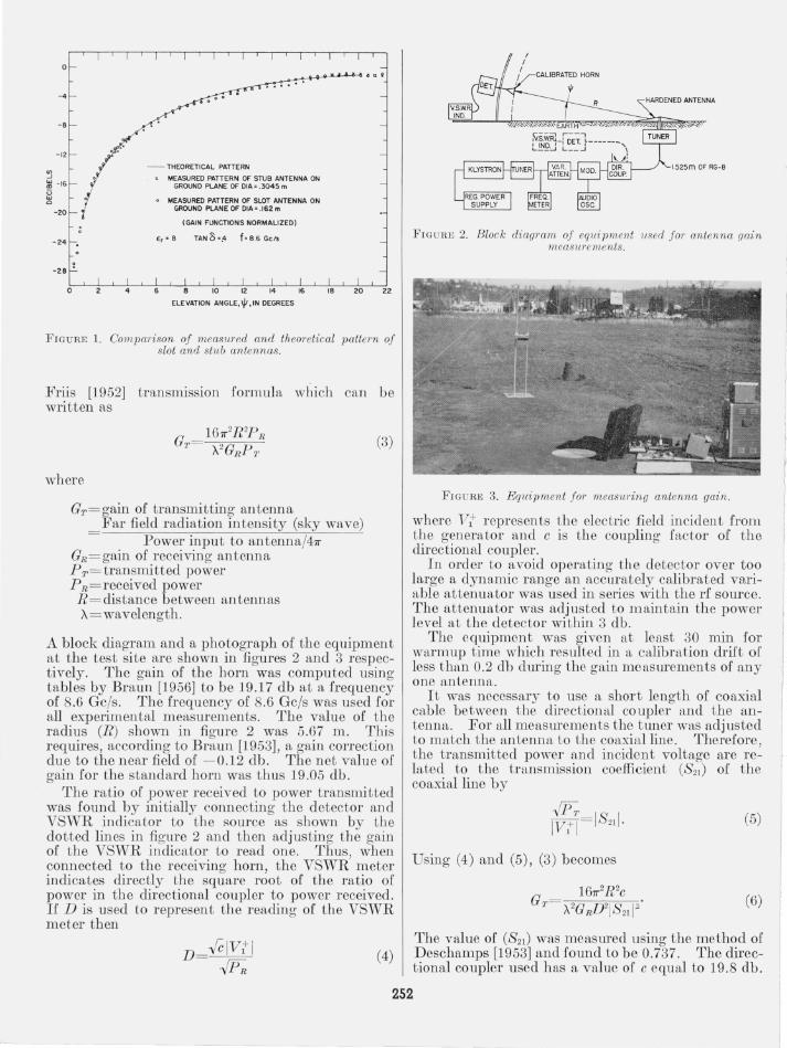
The measured pattern of a quarter wavelength stub is compared in figure 1 with the theoretical expression as given by (1).
The greatest variation with angle occurs from the factor (1 + Rv) which is a consequence of geometric optics for a plane interLace when t.he ground plane effect is ignored. The same factor is obtau1 ed in the geometric optics approA'lmation [King, 1956] for horizontal magnetic dipoles. Thus, we might expect low angle radiation from a slot in a fmi te size ground plane of moderate size to have approximately the same variation. This is confirmed by measurements taken on a half-wave slot, the resul ts of which arc shown in figure 1.
2 . Measurement Technique
Gain was m easured by probing the field about a given antenna with a calibrated or standard horn . Th e gain was determined from Schelkunoff and
J
L
o
- 4
-8
-24
- 28 !
o
- THEORETICAL PATTERN
MEASURED PATTERN OF STUB ANTENNA ON GROUND PLANE OF CIA= .3045 m
MEASURED PATTERN OF SLOT ANTENNA ON GROUND PLANE OF OIA z .162 m
(GAIN FUNCTIONS NORMALIZED)
E,' 8 TAN 13 ·.4 fo 8 .6 Gels
ELEVATION ANGLE.Ijt.IN DEGREES
FIGURE 1. Comparison of measured and theoretical pattern of slot and stub antennas.
Friis [1952] transmission formula which can be written as
where
GT= gain of transmitting antenna Far field radiation intensity (sky wave)
Power input to antenna/47r GR = gain of receiving antenna PT= transmitted power PR=received power R = distance between antennas A= wavelength.
(3)
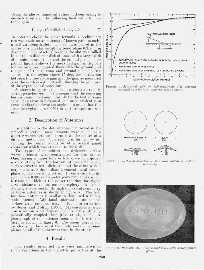
A block diag~'am and a pho.tograph of the equipment a.t the test SIte ~re shown m figures 2 and 3 respectlyely. The gam of the horn was computed using tables by Braun [1956] to be 19.17 db at a frequency of 8.6 Gc/s. The frequency of 8.6 Gcls was used for all experimental measurements. The value of the radius (R) shown in figure 2 was 5.67 m. This requires, according to Braun [1953], a gain correction due to the near field of - 0.12 db. The net value of gain for the standard horn was thus 19.05 db .
The ratio of power received to power transmitted was found by initially connecting the detector and VSWR .indi~ator to the source as shown by the dotted hnes m figure 2 and then adjusting the gain of the VSWR indicator to read one. Thus, when ?on.nected ~o the receiving horn, the VSWR meter mdlCates dlrectly the square root of the ratio of power in the directional coupler to power received. If D is used to represent the reading of the VSWR meter then
(4)
FlGURl, 2. Block diagram of equipment 1lsed for antenna gain measurements.
FIGU RE 3. Equipment for measuring antenna gain.
where Vi represents the electric field incident from the generator and c is the coupling factor of t he directional coupler.
In order to avoid operatino' the detector over too large a dynamic range an acc~rately calibrated variable attenuator was used in series with the rf source. The attenuator was a~ju~ted to maintain the power level at the detector wlthm 3 db.
The equipment was given at least 30 min for warmup time which resulted in a calibration drift of less than 0.2 db dming the gain measmements of any one antenna.
It was necessary to use a short length of coaxial cable between the directional coupler and the antenna. For all measmements the tuner was adjusted to match the antenna to the coaxial line. Therefore the transmitted power and incident voltage are re~ lated to the transmission coefficient (821 ) of the coaxial line by
.[p~ 18 I lVil= 21·
Using (4) and (5), (3) becomes
A2GRU l8 21 I::
(5)
(6)
The value of (821 ) was measmed using the method of Deschamps [1953] and found to be 0.737. The directional coupler used has a value of c equal to 19.8 db .
252
J
(
"
T, I
>
Using the above numerical values and converting to decibels results in the following final value for antenna gain.
10 10glO GT = 29.8 - 10 10glO D . (7)
In order to check the above formula, a preliminary run was made on an antenna of known gain, namely, a haIr-wavelength slot . The slot was placed in the center of a circular metallic ground plane 0.314 min diameter. For practical reasons the slot was milled in a 0.152 m diameter disk of brass with a larger disk of alum inum used to extend the ground plane. The plot in figure 4 shows the measured gain in decibels for the antenna mounted flush with the ground and the gain of the antenna and ground plane in free space. In the region above 15 deg, the correlation between the free space gain and the gain as measUTed over the earth is within 0.5 db, showing the accmacy of the experimental procedure.
As shown in figure 4, the field is attenuated rapidly as 1/1 approaches zero. This means that the receiving horn is illuminated non uniformly by the test antenna causing an errol' in measmed gain 01' equivalently an error in efl'ective elevation angle. In order that this errol' be negligible a 0.0508 m vertical apcrtme was used.
3. Description of Antennas
In addition to the slot antenna mentioned in the preceding section, measurements were made on a quarter-wavelength s tub located at the center of a circular metal disk. The stub was formed by extending the cen ter cond uctor of a coaxial panel connector which was attached to the disk.
Two types of omnidirectional dielectric smlace wave antennas were constructed for this study. One, having a major lobe in free space at approxim.ately 13 deg from the boriz;on, utilir,es a fla t metal surface covered with dielectric and t he other with a major lobe at 8 deg utilizes a conical metal ground pla ne covered with dielectric. In each case the dielectric is a 0.305 m diameter polystyrene (lisk which is 0.635 cm. thick at the center tapering linearly to zero thickness at the outer periphery. A sketch showing a cross section through the axis of symm etry of these antennas is shown in figure 5. The feed for these antennas is similar to that used with the stub antenna. Additional information on conical surface wave antennas may be found in an article by Jones and Folson [1953]. Measurements were also made on a 12 element end fire array utilizing parasitically coupled slo ts [Coe et al. , 1960]. A photograph of t his antenna mounted flush with the earth is shown in figure 6. Provisions were made for changing the size of the finite metallic ground planes on all of the antennas used in the study.
4. Results
The resul ts presented here were insensitive to small variations in the dielectric properties of the
253
~ -4 HALF-WAVELENGTH SLOT
~ 7\';7 ; Jr'7'7'7:j)717J7 J J
--j .314mDlAi--.
- THEORETICAL GAIN OVER INFINITE PERFECTLY CONDUCTING GROUND PLANE
x MEASURED GAIN IN FREE SPACE
o MEASURED GAIN OVER IMPERFECTLY CONDUCTING GROUND
~24~O~~~~4~~6~~8~~~~~12~~14~~'6~~~~-f.20~~22 ELEVATION ANGLE, 'It,IN DEGREES
FIGURE 4. i11easured gain of half-wavelength slot antenna mounted on a 0.314 m diametel' ground plane.
~~'m DIA,
FIGURE 5. Sketch of dielectl'ic sUIJace wave antennas used in this study.
11111111111/
FIG URE 6. Parasitic slot array mounted on a fiat metal ground plane.
-- -------

- 20
HALF-WAVELENGT H SLOT
-THEORETICAL GAIN OVER INFINITE PERFECTLY CONDUCTING GROUND PLANE .
x MEASURED GAIN IN FREE SPACE.
• MEASURED GAIN OVER IMPERFECTLY CONDUCTING PLANE.
- 2·0~L-t-~~~'6~L-ie~-1.,o~-.,~~b-~~~~-.~L,ro~~22
ELE VATION ANGLE. '/t.IN DEGREES
FIGURE 7. lYleasured gain of half-wavelength slot antenna mounted on a 0.466 m diameter ground plane.
.D
"
« z z
'/t~SLOT ARRAY
". L' ~.f - L;~~'DI A . . .466m DIA --J
~ - 4 Z «
• MEASURED GAIN IN FREE SPACE -'2
• MEASURED GAIN OVER IMPERFECTLY CONDUCTING GROUND
-' 60'-L--:-~-L--'--6'-'--.Le --'---"O--'_,LZ --'...-L'4--'---"6--'-"e-'--2LO-,--.J22
ELEVATION AN GLE.'/t.IN DEGREES
FIGURE 8. lYleasw'ed gain of parasitic slot array mounted on a 0.466 m diameter ground plane.
A ."
~ z <i <.0
« z z w - 12 >Z «
r---------.--.:::::~P='~~~
QUARTER -WAVELENGTH STUB
f ,f~l~ " '-:r;~ m DIA.
- THEORETICAL GAIN OV ER INFINITE PERFECTLY CO NDU CTING GROUND PL ANE
x MEASURED GAIN IN FREE S~CE
• MEASURED GAIN OVER IMPERFECTLY CONDUCTING GROUND
' 2·0'-L-~~~~-6~L-~e--'--',0--L,,~L-~'4~~'6~~'~8-'-~--'--i·
ELEVATION ANGLE •• IN DEGREES
F I GURE 9. M~easured gain of quarter-wavelength stub antenna mounted on a 0.305 m diameter ground plane.
254
DIELECTRIC SURFACE WAVE ANTENNA
f----T '1/ 777'" ;:;;Jr7;;:1(lll:I'l1 1- .6I mDIA~
122m DIA .
x ME ASURED GAIN IN FREE SPACE
o MEASURED GAIN OVER IMPERFECTLY CONDUCTING GROUND
' Z~~L-+-~~-L~6~L-~8--'-~'O~~'~2 --'...~'~4~~'6--'~'8~~2~0-'-~2 2· ELE VAT ION ANGLE.'/t. IN DE GREE S
FIGURE 10. lYleasured gain oj dielect,'ic surface wave antenna mounted on a 1. 22 m diameter ground plane.
"" ""
SHADED AREA REPRESENTS SPREAO OF EXPER IMENTAL DATA
-240~L-~~~4~~6~L-~8~--"O~~'~2--'---'-'4--'--"6~'--'~B-'-~OO~~~~ ELEVATION ANGLE.'/t.IN DEGREES
FIGURE 11. Average difference in db between free space gain and gain over earth for all antennas measured in this study.
ear th observed concurrently with the measurements. The average values of rel ative dielectric constant and loss tangent were 9 and 0.5 , respectively. However, with different soils and at other frequencies the dielectric properties may vary appreciably.
Data was taken on each of the antennas with several sizes of ground plane ranging from approximately 0.23 m to 1.22 m in diameter. Typical data is shown in figures 7 through 10. Shown in each figure are two curves plotted in rectangular cOOI'dinates of antenna gain in decibels with respect to the isotropic level for low elevation angles. One of the two curves represents the free space gain as measured on a pattern range while the other curve represents the data obtained with the antenna in the presence of the earth using the measurement technique described in this paper. It will be observed that in each the gain with and withou t the influence of the earth are nearly identical above an elevation angle of around 12 deg. As the elevation angle decreases to zero the antenna gain in each case
~I J I
J i\
I
J I ) I
I
j 1
J I I J
I I ~ I
j I
I I

• 1 ,
/.
I _
(
decreases to zero in a manner similar to that indicated for th e elemental dipoles. Data similar to th a t presented here was obtained on approximately seventeen different an tenna and ground plane combinations. For comparison , the ratio between the free space gain and gain in the presence of the earth was plotted on a single graph for all the configurations measured.! This leads to the conclusion that the ratio between the free space gain and gain on the earth was practically the same for all configurations. The average of this ratio is shown in figure II. This result suggests that one may estimate the behavior of an antenna over conducting earth by measuring the free space gain utilizing simple modeling techniques on a conventional pattern range . The gain over the ground may then be obtained by subtracting the curve of figure 11 from the measured free space gain.
I A tbeoretical ex pression for i he rat io of i he free space gain and the ga in on ibe ear t b bas been deri ved using ihe corrcci ion facia l' (l+!l) and will be publis hed in a future paper.
255
5. References
Bra un, E. H. (Jan. 1953), Gain of electromagnetic horns, Proc. IRE 41, No.1, 109- 115.
Braun, E. H . (Jan. 1956), Some data for the design of electromagneti c hams, IRE Tra ns. PGAP AP- 4, No.1, 29- 3L
Cae, Ri cha rd J ., G. Geld, and A. I shimaru (Mar. 1960), A parasitic slot array, T ech. Rpt. No. 43, D epartment of Electrical Engineering, University of Washington.
D escha mps, G. A. (Aug. 1953), D et ermination of the reflection coefficients and insertion loss of a waveguid e junction, J . AppL Phys. 24, No.8, 1046- 1050.
Jon es, E. M. '1'., and R A. Folsom, Jr. (June 1953) , A note on the circu la r dielectric disk a ntenna, Proc. IRE 41, 798.
King, R W. P . (1956), Theo ry of Ii near a nten nas, p . 794 (Harvard University Press, Ca mbri dge, M ass.).
Schelkunoff, S. A., H. T. Frii s (1 952), Antennas theo ry a nd practice, p. 185 (John ·Wiley & Sons, Inc., New York, N.Y. ).
vVait, J. R (1963), The theo ry of a n a ntenna over a n inhomogeneous ground pla ne, preprin ted from E lect romagneti c Theo ry a nd Antennas, ed. by E. C. J ordon (Perga mon Press, Oxfo rd) .
Wait, J. R , a nd L. C. Walters (1963), Inftuence of a sector grou nd screen on t he field of a verti cal a ntenna, N BS Mono. No. 60.
(Paper 68D2-339)