Effect of Localized Metal Matrix Composite Formation on Spot Senthil...
8
Scott F. Miller Mechanical Engineering, University of Hawaii at Manoa, Honolulu, HI 96822 Senthil G. Arul Department of Navy, Naval Sea Systems Command, Washington, DC 20376 Grant H. Kruger Mechanical Engineering, University of Michigan, Ann Arbor, MI 48109 Tsung-Yu Pan Oak Ridge National Lab, Oak Ridge, TN 37831 Albert J. Shih Mechanical Engineering, University of Michigan, Ann Arbor, MI 48109 Effect of Localized Metal Matrix Composite Formation on Spot Friction Welding Joint Strength In this study, metal particles were added during the spot friction welding (SFW) process, a solid state sheet metal joining process, to create a localized metal matrix composite (MMC) for the improvement of lap shear strength in AISI 6111-T4 aluminum alloy sheets. The Ancorsteel V R 1000 particles were compressed between the upper and lower sheets and distributed concentrically around the tool axis perpendicular to the plate surface, which formed a localized MMC and were effective as the reinforcement particles in alu- minum 6111-T4 alloy sheets. Results revealed that the MMC reinforcement improved the lap shear strength of SFW joints by about 25%. An aluminum-ferrous solid solution was formed around the steel particles along the aluminum matrix interface. The load-deflec- tion curve shows that the steel particle MMC increased both the strength and ductility of SFW joint. This is attributed to two phenomena observed on the failed lap shear tensile specimens with SFW MMC. One is the longer and more torturous crack path, and the other is the secondary crack on steel particle MMC reinforced SFW joints. [DOI: 10.1115/1.4004389] Keywords: friction stir welding, metal matrix composite, joint strength 1 Introduction MMC has proven to provide higher strength, better creep resist- ance, and improved fatigue life compared to unreinforced metals [1]. MMC can be formed by liquid state processing (e.g., infiltra- tion and dispersion) or by solid state processing (e.g., powder con- solidation and diffusion bonding) [2]. Friction stir welding (FSW) is a solid state process that has the potential to create the MMC in-situ at the joint during the welding process. In FSW, a rotating tool traverses along a joint line vigorously stirring the adjacent materials. Frictional heat generated by stirring causes the material to soften and create a solid state bond at the interface between the two sheets. Mishra et al. [3] added reinforcement particles during friction stir welding for the in-process fabrication of a 50–200 lm MMC surface layer. Microhardness of this layer (85–173 Hv) almost doubled with 27% SiC particles compared to the baseline samples of 5083 aluminum alloy. Wang et al. [4] investigated the bulk dispersal of SiCp particles wider and deeper (5 mm  2 mm) into aluminum alloy by the FSW process. A 10% increase in microhardness over the base material (88–97 HV) was found at a depth of 1 mm below the surface. Storjohann et al. [5] found that friction stir welding of 6061-Al 2 O 3 (Al-MMC) composite yielded a good joint without degradation of the microstructure whereas, with fusion welding, disassociation and clumping of Al-Al 2 O 3 composites occurred. SFW is an extension of FSW, where there is no horizontal tra- verse of the tool. In the SFW process, a rotating tool is plunged into two overlapped sheets, which vigorously stirs the material to create a solid state bond. With the increase in the use of light- weight aluminum structures, the automotive industry is faced with new challenges of how to join aluminum alloys without degrading joint performance or increasing cost and weight. For aluminum alloys, as reported in Sun et al. [6], Thornton et al. [7], and Gean et al. [8], the conventional method of joining by resistance spot welding poses many technical issues, which include the weld po- rosity, electrode wear, and inconsistency in failure modes. As a result, the automotive industry is investigating new methods, such as structural adhesives, rivets, and toggle-locks, to join aluminum panels. The SFW process provides a potential optimal solution in terms of joint strength performance, weld quality, and operating cost without adding additional weight [8]. SFW of aluminum is being used in current production on Toyota Prius trunk lid, hood, and the Mazda RX-8 rear doors. These implementations have demonstrated the feasibility of SFW as a production joining method for automotive light-weight aluminum structures. For a given work-material, the SFW joint strength is maximized by optimizing the tool geometry and process parameters. Several studies have been conducted to maximize the joint strength and provide recommendation on process parameters. The conclusions were often mixed. Badarinarayan et al. [9] found that tool geome- try had a significant effect on the partial metallurgical bond formed in the weld region between the overlapped metal sheets. Freeney et al. [10] showed that the higher weld strength was accomplished at a lower spindle speed and increasing the depth of penetration did not significantly contribute to weld strength. How- ever, Sakano et al. [11] and Arul et al. [12] showed that the maxi- mum lap shear load initially increased but then peaked and decreased as spindle speed increased. Beyond process and tool ge- ometry optimization, forming the MMC at SFW joint can further increase the joint strength. Geni and Kikuchi [13] and Bao et al. [14] have conducted theo- retical investigations of MMC. Whitehouse and Clyne [15] cre- ated MMC using spherical Al 2 O 3 particles (diameter of 10 lm), short fibers (diameter of 3 lm), and angular cuboids (diameter of 10–15 lm) with reinforcement volume fractions of 10% and 20% distributed uniformly in a commercially pure aluminum matrix. It is hypothesized that the addition of steel particles during the SFW process will increase the strength and toughness of the joint. The goal of this study is to fully investigate the effect of MMC formation on the SFW joint, including material analysis of the MMC formation and lap shear failure mode and quantification of the lap shear strength. In this paper, Sec. 2 explains the preweld specimen preparation and SFW processing to create the MMC. The results of postweld joint strength analysis with and without MMC, microstructure, and SEM analysis on the formation of the MMC are discussed in Sec. 3. Sections 4 and 5 provide failure Contributed by the Materials Division of ASME for publication in the JOURNAL OF ENGINEERING MATERIALS AND TECHNOLOGY. Manuscript received March 31, 2010; final manuscript received May 27, 2011; published online July 18, 2011. Assoc. Editor: Mohammad A. Khaleel. Journal of Engineering Materials and Technology JULY 2011, Vol. 133 / 031009-1 Copyright V C 2011 by ASME Downloaded 23 Sep 2011 to 141.213.236.110. Redistribution subject to ASME license or copyright; see http://www.asme.org/terms/Terms_Use.cfm
-
Upload
nguyenthien -
Category
Documents
-
view
216 -
download
2
Transcript of Effect of Localized Metal Matrix Composite Formation on Spot Senthil...
Scott F. MillerMechanical Engineering,
University of Hawaii at Manoa,
Honolulu, HI 96822
Senthil G. ArulDepartment of Navy,
Naval Sea Systems Command,
Washington, DC 20376
Grant H. KrugerMechanical Engineering,
University of Michigan,
Ann Arbor, MI 48109
Tsung-Yu PanOak Ridge National Lab,
Oak Ridge, TN 37831
Albert J. ShihMechanical Engineering,
University of Michigan,
Ann Arbor, MI 48109
Effect of Localized Metal MatrixComposite Formation on SpotFriction Welding Joint StrengthIn this study, metal particles were added during the spot friction welding (SFW) process,a solid state sheet metal joining process, to create a localized metal matrix composite(MMC) for the improvement of lap shear strength in AISI 6111-T4 aluminum alloy sheets.The AncorsteelV
R
1000 particles were compressed between the upper and lower sheetsand distributed concentrically around the tool axis perpendicular to the plate surface,which formed a localized MMC and were effective as the reinforcement particles in alu-minum 6111-T4 alloy sheets. Results revealed that the MMC reinforcement improved thelap shear strength of SFW joints by about 25%. An aluminum-ferrous solid solution wasformed around the steel particles along the aluminum matrix interface. The load-deflec-tion curve shows that the steel particle MMC increased both the strength and ductility ofSFW joint. This is attributed to two phenomena observed on the failed lap shear tensilespecimens with SFW MMC. One is the longer and more torturous crack path, and theother is the secondary crack on steel particle MMC reinforced SFW joints.[DOI: 10.1115/1.4004389]
Keywords: friction stir welding, metal matrix composite, joint strength
1 Introduction
MMC has proven to provide higher strength, better creep resist-ance, and improved fatigue life compared to unreinforced metals[1]. MMC can be formed by liquid state processing (e.g., infiltra-tion and dispersion) or by solid state processing (e.g., powder con-solidation and diffusion bonding) [2]. Friction stir welding (FSW)is a solid state process that has the potential to create the MMCin-situ at the joint during the welding process. In FSW, a rotatingtool traverses along a joint line vigorously stirring the adjacentmaterials. Frictional heat generated by stirring causes the materialto soften and create a solid state bond at the interface between thetwo sheets. Mishra et al. [3] added reinforcement particles duringfriction stir welding for the in-process fabrication of a 50–200 lmMMC surface layer. Microhardness of this layer (85–173 Hv)almost doubled with 27% SiC particles compared to the baselinesamples of 5083 aluminum alloy. Wang et al. [4] investigated thebulk dispersal of SiCp particles wider and deeper (5 mm� 2 mm)into aluminum alloy by the FSW process. A 10% increase inmicrohardness over the base material (88–97 HV) was found at adepth of 1 mm below the surface. Storjohann et al. [5] found thatfriction stir welding of 6061-Al2O3 (Al-MMC) composite yieldeda good joint without degradation of the microstructure whereas,with fusion welding, disassociation and clumping of Al-Al2O3
composites occurred.SFW is an extension of FSW, where there is no horizontal tra-
verse of the tool. In the SFW process, a rotating tool is plungedinto two overlapped sheets, which vigorously stirs the material tocreate a solid state bond. With the increase in the use of light-weight aluminum structures, the automotive industry is faced withnew challenges of how to join aluminum alloys without degradingjoint performance or increasing cost and weight. For aluminumalloys, as reported in Sun et al. [6], Thornton et al. [7], and Geanet al. [8], the conventional method of joining by resistance spotwelding poses many technical issues, which include the weld po-rosity, electrode wear, and inconsistency in failure modes. As a
result, the automotive industry is investigating new methods, suchas structural adhesives, rivets, and toggle-locks, to join aluminumpanels. The SFW process provides a potential optimal solution interms of joint strength performance, weld quality, and operatingcost without adding additional weight [8]. SFW of aluminum isbeing used in current production on Toyota Prius trunk lid, hood,and the Mazda RX-8 rear doors. These implementations havedemonstrated the feasibility of SFW as a production joiningmethod for automotive light-weight aluminum structures.
For a given work-material, the SFW joint strength is maximizedby optimizing the tool geometry and process parameters. Severalstudies have been conducted to maximize the joint strength andprovide recommendation on process parameters. The conclusionswere often mixed. Badarinarayan et al. [9] found that tool geome-try had a significant effect on the partial metallurgical bondformed in the weld region between the overlapped metal sheets.Freeney et al. [10] showed that the higher weld strength wasaccomplished at a lower spindle speed and increasing the depth ofpenetration did not significantly contribute to weld strength. How-ever, Sakano et al. [11] and Arul et al. [12] showed that the maxi-mum lap shear load initially increased but then peaked anddecreased as spindle speed increased. Beyond process and tool ge-ometry optimization, forming the MMC at SFW joint can furtherincrease the joint strength.
Geni and Kikuchi [13] and Bao et al. [14] have conducted theo-retical investigations of MMC. Whitehouse and Clyne [15] cre-ated MMC using spherical Al2O3 particles (diameter of 10 lm),short fibers (diameter of 3 lm), and angular cuboids (diameter of10–15 lm) with reinforcement volume fractions of 10% and 20%distributed uniformly in a commercially pure aluminum matrix.
It is hypothesized that the addition of steel particles during theSFW process will increase the strength and toughness of the joint.The goal of this study is to fully investigate the effect of MMCformation on the SFW joint, including material analysis of theMMC formation and lap shear failure mode and quantification ofthe lap shear strength. In this paper, Sec. 2 explains the preweldspecimen preparation and SFW processing to create the MMC.The results of postweld joint strength analysis with and withoutMMC, microstructure, and SEM analysis on the formation of theMMC are discussed in Sec. 3. Sections 4 and 5 provide failure
Contributed by the Materials Division of ASME for publication in the JOURNAL OF
ENGINEERING MATERIALS AND TECHNOLOGY. Manuscript received March 31, 2010; finalmanuscript received May 27, 2011; published online July 18, 2011. Assoc. Editor:Mohammad A. Khaleel.
Journal of Engineering Materials and Technology JULY 2011, Vol. 133 / 031009-1Copyright VC 2011 by ASME
Downloaded 23 Sep 2011 to 141.213.236.110. Redistribution subject to ASME license or copyright; see http://www.asme.org/terms/Terms_Use.cfm

mechanisms and a discussion regarding the results in terms of ourhypothesis, respectively. Conclusions and the next steps are pre-sented in Sec. 6.
2 Experimental Setup
2.1 Tool, Fixture, and Machine. The Mori-Seiki ModelTV-30 CNC controlled machine, shown in Fig. 1(a), was used toproduce the displacement controlled SFW welds presented in thisstudy. Figure 1(b) shows the fixture used to secure the upper andlower coupons of the materials to be welded. A zirconium (ZrO2)ceramic anvil was used to support the workpiece. ZrO2 has lowthermal conductivity to reduce the conduction heat loss during theSFW process and facilitate higher nugget temperatures. Over thetop of the weld, a rigid steel fixturing cover plate was used toensure the coupons were in good contact and to minimize the sep-aration and plasticized material flow between the upper and lowerworkpiece during the SFW process. A 15 mm diameter hole in thecover plate provided access to the center of the overlap area onthe workpiece where the SFW process takes place.
The SFW tool was made of H13 tool steel with a hardness ofRc 47–50. The tool had a concave shoulder with 10 mm diameterand a pin with left-handed threads (inner and outer diameter of 1.7and 2.5 mm, respectively).
2.2 Specimens and Particles. The work-material is AISI6111-T4 aluminum alloy, the most widely used aluminum alloy inautomotive body panels. The rectangular aluminum sheets werecut into 25.4� 101.6 mm coupons, and the specimens were pre-pared by stacking a 1.3 mm thick coupon over a 1.5 mm thickcoupon with a 25.4� 25.4 mm overlap. The coupons were thor-oughly cleaned using acetone to remove all foreign material. Thechemical composition of Al 6111-T4 is shown in Table 1.
AncorsteelVR
1000 particles [16] with sizes ranging from 45 to250 lm, as shown in Fig. 2, were used as the reinforcement par-ticles for SFW MMC formation. The Ancorsteel
VR
particles werechosen because they were found to provide improved embeddingand joint strengthening than SiC, Al12Si, or Cu particles in an em-pirical study [17]. The Ancorsteel
VR
particles were manufacturedby atomizing molten steel to form irregular, homogeneous par-ticles. The chemical composition of Ancorsteel
VR
1000 and the alu-minum 6111-T4 work material are shown in Table 1.
2.3 Experimental Procedure. Figure 3 illustrates the steelparticles and MMC formation process in the SFW joint. For eachMMC specimen, approximately 15 mg of steel particles wereweighed. The steel particles were then placed on the upper surfaceof the lower coupon where the vertical axis of SFW tool intersectsthe workpiece (center point of the overlapping area). The uppercoupon was then placed on top of the steel particles, taking carenot to significantly disturb the particles. Thereafter, the couponswere clamped under the steel cover plate, sandwiching the par-ticles between the upper and lower coupons, as illustrated inFig. 3.
The ZrO2 support marked as anvil in Fig. 3 is placed under thelower coupon to support the tool’s axial force during SFW andminimizes the heat loss to the anvil. In the second step, Fig. 3, therotating tool plunges into the surface of the upper specimen,resulting in a large axial force, and through the combination of thekinetic friction and axial force, frictional heat is generated. Theheated and softened material adjacent to the tool deforms plasti-cally in a vortex like motion, and a solid state bond is created atthe interface of the upper and the lower sheets. The vortex motionis largely influenced by the process parameters and tool geometryand determines the final distribution of the supporting material inthe joint. In the final step, Fig. 3, the tool is withdrawn from thecoupons. The duration from when the tool pin initially contactsthe upper sheet until the tool begins to be drawn out is defined asthe cycle time.
After two coupons are spot friction welded together, they arereferred to as a specimen in this paper. Three baseline and fiveMMC experiments were successfully completed, and the order ofexperiments was randomized to reduce the influence of systematicerrors in the data collection. Of the four specimens, three wereused for lap shear testing and one for microstructure analysis.
Fig. 1 Machine and fixture used to produce samples: (a) over-view of SFW experimental setup and (b) fixture
Table 1 Chemical composition of aluminum 6111- T4 andAncorsteel
VR
1000 particles
6111-T4 Ancor steel particle
Si 0.6 C <0.01Fe 0.4 O 0.14Cu 0.5-0.9 N 0.002Mn 0.1-0.45 S 0.018Mg 0.1 P 0.009Cr 0.15 Si <0.01Zn 0.15 Mn 0.2Ti 0.1 Cr 0.07Other 0.05 Cu 0.1Al Rest Fe Rest
Fig. 2 SEM micrograph of AncorsteelVR
1000 particles
031009-2 / Vol. 133, JULY 2011 Transactions of the ASME
Downloaded 23 Sep 2011 to 141.213.236.110. Redistribution subject to ASME license or copyright; see http://www.asme.org/terms/Terms_Use.cfm
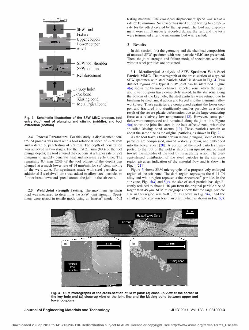
2.4 Process Parameters. For this study, a displacement con-trolled process was used with a tool rotational speed of 2250 rpmand a depth of penetration of 2.5 mm. The depth of penetrationwas achieved in two stages. For the first 2.1 mm (80% of the toolplunge depth), the tool entered the coupons at a higher rate of 272mm/min to quickly generate heat and increase cycle time. Theremaining 0.4 mm (20% of the tool plunge of the depth) wasplunged at a much lower rate of 14 mm/min for sufficient mixingin the weld zone. For specimens made with steel particles, anadditional 2 s of dwell time was added to allow steel particles tofurther breakdown and spread around the joint in the stir zone.
2.5 Weld Joint Strength Testing. The maximum lap shearload was measured to determine the SFW joint strength. Speci-mens were tested in tensile mode using an Instron
VR
model 4502
testing machine. The crosshead displacement speed was set at arate of 10 mm/min. No spacer was used during testing to compen-sate for the offset created by the lap joint. The load and displace-ment were simultaneously recorded during the test, and the testswere terminated after the maximum load was reached.
3 Results
In this section, first the geometry and the chemical compositionof untested SFW specimen with steel particle MMC are presented.Then, the joint strength and failure mode of specimens with andwithout steel particles are presented.
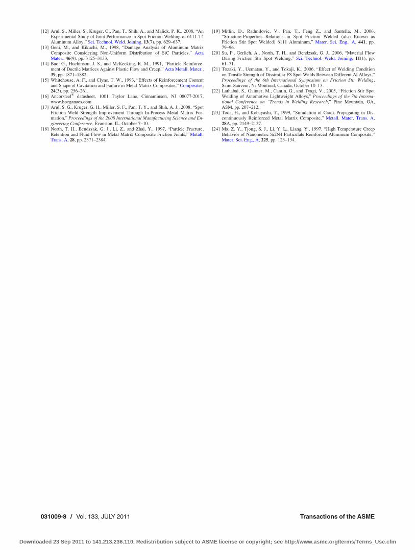
3.1 Metallurgical Analysis of SFW Specimen With SteelParticle MMC. The macrograph of the cross-section of a typicalSFW specimen with steel particle MMC is shown in Fig. 4. Twodistinct regions of a typical SFW joint can be identified. Figure4(a) shows the thermomechanical affected zone, where the upperand lower coupons have completely mixed. In the stir zone alongthe bottom of the key hole, the steel particles were refined due tobreaking by mechanical action and forged into the aluminum alloyworkpiece. These particles are compressed against the lower cou-pon and fractured into significantly smaller particles as a directresult of the severe plastic deformation due to the large contactingforce at a relatively low temperature [18]. However, some par-ticles were compressed and remained along the joint line. Figure4(b) shows the joint line area in the heat affected zone, where theso-called kissing bond occurs [19]. These particles remain atabout the same size as the original particles, as shown in Fig. 2.
As the tool travels further down during plunging, some of theseparticles are compressed, moved vertically down, and embeddedinto the lower sheet [20]. A portion of the steel particles trans-ported to the root of the weld is also drawn upward and outwardtoward the shoulder of the tool by its auguring action. The cres-cent-shaped distribution of the steel particles in the stir zoneregion gives an indication of the material flow and is shown inFig. 4 [21].
Figure 5 shows SEM micrographs of a progressively enlargedregion of the stir zone. The dark region represents the 6111-T4alloy and white region represents the Ancorsteel
VR
particle. In thestir zone, Figs. 5(d) and 5(e), the size of steel particle has signifi-cantly reduced to about 1–10 lm from the original particle size oflarger than 45 lm. SEM micrographs show that the large particlesize in this region was 8–10 lm, as shown in Fig. 5(d), and thesmall particle size was less than 3 lm, which is shown in Fig. 5(f).
Fig. 3 Schematic illustration of the SFW MMC process, toolentry (top), end of plunging and stirring (middle), and toolextraction (bottom)
Fig. 4 SEM micrographs of the cross-section of SFW joint: (a) close-up view at the corner ofthe key hole and (b) close-up view of the joint line and the kissing bond between upper andlower coupons
Journal of Engineering Materials and Technology JULY 2011, Vol. 133 / 031009-3
Downloaded 23 Sep 2011 to 141.213.236.110. Redistribution subject to ASME license or copyright; see http://www.asme.org/terms/Terms_Use.cfm

In some areas between the steel particle and the 6111-T4 alloy,a transition zone exists. For example, Fig. 5(f) shows the graytransition zone surrounding a steel particle. An elemental compo-sition by energy dispersive X-ray (EDX) analysis of this area isshown in Fig. 6. In the dark region (marked as A), which is the6111-T4 base material, the aluminum (Al) dominates the distribu-tion. In the white region (marked as B), where the Ancorsteel
VR
particle is present, iron (Fe) dominates the distribution. In the grayregion at the interface between the particle and aluminum alloybase material (marked as C), a solid solution between the alumi-num and iron is formed. The EDX chemical composition based onweight of three selected particles, which formed solid solution inthe stir zone, is shown in Table 2. Particle 1 is the same as thatshown in Fig. 5(f). The remaining two particles, namely particle 2and particle 3, were chosen through random selection. In the ma-trix, as expected, aluminum dominated the X-ray count and itranged from 84% to 97%. Similarly, in the steel particle, irondominated the X-ray count and it ranged from 79% to 87%. In thesolid solution, aluminum ranged from 21% to 61% and ironranged from 36% to 79%.3.2 Effect of Steel Particle MMC onSFW Lap Shear Strength.
The average of maximum lap shear load and the average dis-placement at the maximum load for the three baseline and fiveparticle MMC SFW specimens are shown in Table 3. The averagemaximum load for specimens with particle MMC was 25% higherthan that of the baseline specimen, and the displacement at maxi-mum load was 55% higher for the particle MMC specimens com-pared to the baseline.
Macrographs of the tested specimens (baseline and with steelparticle MMC) with enlarged views of the fracture region areshown in Figs. 7(a) and 7(b), respectively. For both specimens,the crack initiated at the outer joint interface between the upperand lower coupons and traveled upward and inward toward thefree edge of the shoulder surface. The load deflection curve of
three samples, one baseline and two MMC SFW specimens, areprovided in Fig. 8. After the initial rigid body movement due toslack, an elastic deformation region can be identified up to about0.8 kN loading. Beyond the elastic region, the slope of the load-deflection curve for the MMC specimens is smaller than the base-line specimens (sample #1 in Fig. 8). The small cracks observeddue to the presence of steel particles were thought to cause largervoids in the reinforced material as it was stretched [2]. Since thereinforcement particles are settled between the transition pointand the free edge of the shoulder, as shown in Fig. 4(b), it isthought that this crack path must fracture through or around thesteel particles, progressing via void nucleation and growth to fail-ure, as observed in Fig. 7. The samples with this torturous crackpath and void nucleation growth also have higher displacementand higher fracture loads for the MMC specimens compared tobaseline specimens.
The load-deflection curve obtained from the MMC SFW jointis similar to that of the homogenous material, as shown in Fig. 8.However, typical stress-stain curves of MMC show that they aregenerally stiffer than the homogeneous material [14]. Visual ex-amination of specimens revealed that both the baseline and theMMC specimens failed by ductile mixed mode fracture. Two outof the three tested specimens of the MMC exhibited a half-moonshaped secondary crack in addition to the primary crack, whichwas not present in the baseline specimens. Pictures of the primarycrack of the baseline specimen (sample #1-baseline) and primaryand secondary cracks of one of the MMC specimens (sample #3-MMC) are shown in Fig. 9. Sample #2-MMC did not have a sec-ondary crack.
In this study, for both baseline and particle MMC coupons, thecrack originated in the kissing bond region [19]. Once the crack isinitiated, the crack tip can travel toward either the free edge of thepin hole resulting in shear fracture or the free edge of the shoulderresulting in mixed mode fracture [22]. Both the baseline and theparticle reinforced MMC specimens exhibited mixed mode frac-ture, whereby the front edge of the crack tip reaches the free edge
Fig. 5 SEM micrographs of the stir zone showing the steel particle sizes anddistributions
Fig. 6 EDX chemical composition analysis of steel particlehighlighted in Fig. 5(f)
Table 2 Percentage chemical composition (by weight) of threeselected particles in the stir zone
Particle 1 Particle 2 Particle 3
Al Fe Other Al Fe Other Al Fe Other
Matrix 94 3 3 84 14 3 97 2 1Interface 61 36 3 33 66 1 25 74 1Steel particle 14 85 1 20 79 1 12 87 1
031009-4 / Vol. 133, JULY 2011 Transactions of the ASME
Downloaded 23 Sep 2011 to 141.213.236.110. Redistribution subject to ASME license or copyright; see http://www.asme.org/terms/Terms_Use.cfm

of the shoulder indentation on the upper sheet, travels along thecircumference near the shoulder indentation, and finally tears off.
The mechanism of crack initiation is different between thebaseline and particle MMC specimens. In the case of baselinespecimen, which is a homogeneous material, due to the stress in-tensity factor, load, specimen, and weld geometry, the strain levelreaches a critical value, a crack is formed at the transition point,and the front edge travels along the circumference of the shoulderindentation and separates at the other end of the weld. In the caseof particle MMC specimens, the steel particles are clusteredbetween the joint line and the free edge of the shoulder surface ofthe upper coupon, Fig. 4(b). During the lap shear loading, withincrease in load, the void quantity as well as the void size increasebetween the reinforcement particles and the matrix [15]. Thesevoids are considered as microcracks. Once the main crack reachesthe transition region, C in Fig. 6, the forward movement of themain crack is influenced by these microcracks. The microcracksare ahead of the front tip of the main crack, and the main crackpath is deflected toward these microcracks [23]. The microcrackssubsequently become part of the main crack, resulting in a tortur-ous crack path. In some instances, the reinforcement particleswere damaged during the processing or large enough so that theydeveloped cracks and joined the main crack path. In this study,both microcracks and particle fracture were observed, as shown inFig. 10. The particle cracking is illustrated in Fig. 10(a), wherebylarger particles have greater propensity to fracture. The othermethod is where voids at the interface between the steel particlesand the matrix grow and aid in failure process and is illustrated inFig. 10(b).
3.3 Effect of MMC on Material Stiffness, Strength, andFailure Mode. Postmortem microstructure analysis of sample#2-MMC and sample #3-MMC was carried out to explain the dif-ferences in the load-deflection curves. A cross-sectional macro-graph of sample #2-MMC and enlarged view of the failed area,
divided into three regions, is shown in Fig. 11. In region I, withvery few reinforcement steel particles, the failure mode and theload-deflection curve are expected to be similar to those of thebaseline. In region II, nonuniformly distributed steel particles oflarger size (> 30 lm) have high stress concentration, resulting inyielding of the matrix at a lower stress at particle/matrix interface.This results in a more compliant load-deflection curve and a tor-turous crack path since the crack propagates around the steel par-ticles. In region III, agglomerated steel particles with goodbonding in the matrix strengthen MMC [24]. With SFW MMC,both particle cracking and matrix failure occurred to extend thecrack path, as shown in Fig. 10, but the crack path is not torturousenough to increase the total elongation by 55% compared to thatof the baseline. Therefore, there must be some other phenomenonhappening in region III that increases the total elongation. Onepossible explanation is that, in another cross-section in this area,there is very little reinforcement from particles, and the crack path
Table 3 Average maximum lap shear load and the averagedisplacement at maximum load for baseline and particle MMC
Maximum loadkN (standard deviation)
Displacement atmaximum load (mm)
Base 3.2 (0.097) 0.85Particle MMC 4.0 (0.169) 1.32Percent increase byparticle MMC (%)
25 55
Fig. 7 Macrographs of tested specimens showing enlargedview of cracked area in (a) without steel particle MMC (baseline)and (b) with steel particle MMC
Fig. 8 Load-deflection curves for the baseline specimen (sample #1-baseline) andparticle reinforced MMC specimens (sample #2-MMC and sample #3-MMC)
Journal of Engineering Materials and Technology JULY 2011, Vol. 133 / 031009-5
Downloaded 23 Sep 2011 to 141.213.236.110. Redistribution subject to ASME license or copyright; see http://www.asme.org/terms/Terms_Use.cfm

travels in and out of the plane while the load is being carried bythe agglomerated reinforcement particles.
The bottom side of the upper sheet and top side of the lowersheet of the sample #3-MMC were analyzed for more informationabout the area of failure. The SEM back scattered images, shownin Fig. 12, indicate that the secondary cracks occurred in the areawhere the particles (bright color) are distributed. The back scat-tered images also show that the particles in these surfaces are con-centrated (nonuniform distribution) on the upper coupon. Thisnonuniform distribution results in high stress concentration at theparticle/matrix interface, resulting in yielding of the matrix mate-rial at a lower stress compared to that of the baseline. A progres-sively enlarged view of the secondary crack on the bottom side ofthe upper sheet of sample #3-MMC is shown in Fig. 13. Based oncup-cone features exhibited at the failed surface, the specimen inthis area failed by ductile failure. An SEM EDX analysis wasdone on the bottom side of the upper sheet and top of side of thelower sheet, as shown in Fig. 14. The EDX analysis shows thatthe bottom side of the upper sheet had 6111-T4 alloy and the topside of the lower sheet contained both the aluminum and ironfrom the sheets and particles. The absence of steel particles on thebottom side of the upper sheet and steel reinforcement particlesforming intermetallic compound with aluminum at the top side ofthe bottom sheet confirms that the yielding occurred at the parti-cle/matrix interface first and then the crack initiated by voidnucleation.
Fig. 9 Visual examination of the mating surfaces of the (a) baseline (sample #1-baseline) and (b) MMC (sample #3-MMC) specimens showing primary and second-ary cracks
Fig. 10 Crack propagation by (a) particle fracture and (b) voidnucleation
Fig. 11 Cross-sectional macrograph of sample #2-MMC andenlarged view of the fractured area showing nonuniform distri-bution of reinforcement particles
Fig. 12 SEM back scattered image of the sample #3-MMCshowing the primary and secondary crack occur at the rein-forcement particle interface
031009-6 / Vol. 133, JULY 2011 Transactions of the ASME
Downloaded 23 Sep 2011 to 141.213.236.110. Redistribution subject to ASME license or copyright; see http://www.asme.org/terms/Terms_Use.cfm

4 Conclusions
Using the SFW process, localized MMC was formed in theweld nugget. Steel particles were distributed throughout the ther-momechanically affected zone. In some cases, solid solutionswere formed between the steel particle and aluminum 6111-T4alloy. The results showed that the maximum lap shear loadincreased by 25% with steel particle MMC compared to that ofthe baseline. The 55% higher displacement in the load deflectioncurve and the crack geometry of the failed specimens indicatedthat the crack path is more torturous and, therefore, longer for thesteel particle MMC compared to that of the baseline. This couldbe seen through SEM and EDX analyses along the joint interfacethat revealed a localized MMC was being formed, which impededthe crack propagation. This increase in the length of the crackpath leads to an increase in the maximum lap shear load for thesteel particle MMC SFW.
The selection of particles for SFW MMC is a good futureresearch topic. The Ancorsteel
VR
1000 particle was selected aftertrial testing of different types of particles. A better understandingof the MMC reinforcement mechanism in SFW and more exten-sive testing could help the future particle type and size selectionto further improve both the strength and ductility in SFW.
Acknowledgment
We acknowledge the support from Ford Motor Company andNSF CMMI Grant No. 0700617.
References[1] Chawla, N., and Chawla, K. K., 2006, Metal Matrix Composites, Springer,
Berlin.[2] Suresh, S., Mortensen, A., and Needleman, A., 1993, Fundamentals of Metal
Matrix Composites, Butterworth-Heineman, Oxford, UK.[3] Mishra, R. S., Ma, Z. Y., and Charit, I., 2003, “Friction Stir Processing: A
Novel Technique for Fabrication of Surface Composite,” Mater. Sci. Eng., A,341, pp. 307–310.
[4] Wang, W., Shi, Q., Liu, P., Li, H., and Li, T., 2009, “A Novel Way to ProduceBulk Sicp Reinforced Aluminum Metal Matrix Composites by Friction StirProcessing,” J. Mater. Process. Technol., 209, pp. 2099–2103.
[5] Storjohann, D., Barabash, O. M., Babu, S. S., David, S., and Sklad, P., 2005,“Fusion and Stir Welding of Aluminum-Metal-Matrix Composites,” Metall.Mater. Trans. A, 36A, pp. 3237–3247.
[6] Sun, X., Stephens, E., Davies, R., Khaleel, M., and Spinella, D. J., 2005,“Effects of Failure Modes on Strength of Aluminum Resistance Spot Welds,”Society of Automotive Engineers, Warrendale, PA, SAE Technical Paper No:2005-01-0906.
[7] Thornton, P., Krause, A., and Davies, R., 1996, “Aluminum Spot Weld,” Weld.J. (Miami, FL, U.S.), 75, pp. 101s–108s.
[8] Gean, A., Westgate, S. A., Kucza, J. C., and Ehrstorm, J. C., 1999, “Static andFatigue Behavior of Spot-Welded 5182-0 Aluminum Alloy Sheet,” Weld. J.(Miami, FL, U.S.), 78, pp. 80s–86s.
[9] Badarinarayan, H., Shi, Y., Li, X., and Okamoto, K., 2009, “Effect of ToolGeometry on Hook Formation and Static Strength of Friction Stir Spot WeldedAluminum 5754-O Sheets,” Int. J. Mach . Tools Manuf., 49, pp. 814–823.
[10] Freeney, T. A., Sharma, S. R., and Mishra, R. S., 2006, “Effect of Welding Pa-rameters on Properties of 5052 Al Friction Stir Spot Welds,” Society of Auto-motive Engineers, Warrendale, PA, SAE Technical Paper No: 2006-01-0969.
[11] Sakano, R., Murakami, K., Yamashita, K., Hyoe, T., Fujimoto, M., Inuzuka,M., Nagao, Y., and Kashiki, H., 2001, “Development of Spot FSW Robot Sys-tem for Automobile Body Members,” Proceedings of the 3rd InternationalSymposium on Friction Stir Welding, Kobe, Japan.
Fig. 13 Progressively enlarged view of the primary and secondary cracks
Fig. 14 (a) SEM picture of bottom side of upper sheet, (b) EDX analysis of themarked area, (c) SEM picture of top side of bottom sheet, (d) back scattered imageof (c), and (e) EDX analysis of marked area in (c)
Journal of Engineering Materials and Technology JULY 2011, Vol. 133 / 031009-7
Downloaded 23 Sep 2011 to 141.213.236.110. Redistribution subject to ASME license or copyright; see http://www.asme.org/terms/Terms_Use.cfm
[12] Arul, S., Miller, S., Kruger, G., Pan, T., Shih, A., and Malick, P. K., 2008, “AnExperimental Study of Joint Performance in Spot Friction Welding of 6111-T4Aluminum Alloy,” Sci. Technol. Weld. Joining, 13(7), pp. 629–637.
[13] Geni, M., and Kikuchi, M., 1998, “Damage Analysis of Aluminum MatrixComposite Considering Non-Uniform Distribution of SiC Particles,” ActaMater., 46(9), pp. 3125–3133.
[14] Bao, G., Huchinson, J. S., and McKeeking, R. M., 1991, “Particle Reinforce-ment of Ductile Matrices Against Plastic Flow and Creep,” Acta Metall. Mater.,39, pp. 1871–1882.
[15] Whitehouse, A. F., and Clyne, T. W., 1993, “Effects of Reinforcement Contentand Shape of Cavitation and Failure in Metal-Matrix Composites,” Composites,24(3), pp. 256–261.
[16] AncorsteelVR
datasheet, 1001 Taylor Lane, Cinnaminson, NJ 08077-2017,www.hoeganaes.com
[17] Arul, S. G., Kruger, G. H., Miller, S. F., Pan, T. Y., and Shih, A. J., 2008, “SpotFriction Weld Strength Improvement Through In-Process Metal Matrix For-mation,” Proceedings of the 2008 International Manufacturing Science and En-gineering Conference, Evanston, IL, October 7–10.
[18] North, T. H., Bendzsak, G. J., Li, Z., and Zhai, Y., 1997, “Particle Fracture,Retention and Fluid Flow in Metal Matrix Composite Friction Joints,” Metall.Trans. A, 28, pp. 2371–2384.
[19] Mitlin, D., Radmilovic, V., Pan, T., Feng Z., and Santella, M., 2006,“Structure-Properties Relations in Spot Friction Welded (also Known asFriction Stir Spot Welded) 6111 Aluminum,” Mater. Sci. Eng., A, 441, pp.79–96.
[20] Su, P., Gerlich, A., North, T. H., and Bendzsak, G. J., 2006, “Material FlowDuring Friction Stir Spot Welding,” Sci. Technol. Weld. Joining, 11(1), pp.61–71.
[21] Tozaki, Y., Uematsu, Y., and Tokaji, K., 2006, “Effect of Welding Conditionon Tensile Strength of Dissimilar FS Spot Welds Between Different Al Alloys,”Proceedings of the 6th International Symposium on Friction Stir Welding,Saint-Sauveur, Nr Montreal, Canada, October 10–13.
[22] Lathabai, S., Oainter, M., Cantin, G., and Tyagi, V., 2005, “Friction Stir SpotWelding of Automotive Lightweight Alloys,” Proceedings of the 7th Interna-tional Conference on “Trends in Welding Research,” Pine Mountain, GA,ASM, pp. 207–212.
[23] Toda, H., and Kobayashi, T., 1999, “Simulation of Crack Propagating in Dis-continuously Reinforced Metal Matrix Composite,” Metall. Mater. Trans. A,28A, pp. 2149–2157.
[24] Ma, Z. Y., Tjong, S. J., Li, Y. L., Liang, Y., 1997, “High Temperature CreepBehavior of Nanometric Si2N4 Particulate Reinforced Aluminum Composite,”Mater. Sci. Eng., A, 225, pp. 125–134.
031009-8 / Vol. 133, JULY 2011 Transactions of the ASME
Downloaded 23 Sep 2011 to 141.213.236.110. Redistribution subject to ASME license or copyright; see http://www.asme.org/terms/Terms_Use.cfm