Effect of lateral support of compression flange to ... of lateral support of compression flange to...
18
Author: Ferenc Papp, PhD 1 Effect of lateral support of compression flange to stability of beam-columns General Lateral supports of the compression flange of beam-columns (or frames) may drastically increase the critical load amplifier. Higher critical load amplifier normally leads to higher global stability resistance. The ConSteel program provides easily used finite element method to calculate the critical load amplifier of structural members and frames with simple or more complicated supporting system. The features of the applied method are summarized in the following table: categories of models and analysis details of method imperfections no analysis second order and eigenvalue examination of structural members general method (using conservative interaction formula) Numerical example This example presents a study on the stability analysis of structural member where the compression flange is stabilized by wall beams. The model is built up with shell and beam elements. The structural model has the following dimensions: • Height of the column: 10.000 mm • Flange: 300-16 • Web: 800-8 • Span of wall beams: 2 x 6.000 mm • Profile of wall beams: RHS 200.100.4 • Supporting bars: SHS 60.3 • Design moment at top of column: 800 kNm (in the plane of the web) • Grade of steel: S355
Transcript of Effect of lateral support of compression flange to ... of lateral support of compression flange to...

Author: Ferenc Papp, PhD
1
Effect of lateral support of compression flange to stability of beam-columns General Lateral supports of the compression flange of beam-columns (or frames) may drastically increase the critical load amplifier. Higher critical load amplifier normally leads to higher global stability resistance. The ConSteel program provides easily used finite element method to calculate the critical load amplifier of structural members and frames with simple or more complicated supporting system. The features of the applied method are summarized in the following table:
categories of models and analysis details of method imperfections no analysis second order and eigenvalue examination of structural members
general method (using conservative interaction formula)
Numerical example This example presents a study on the stability analysis of structural member where the compression flange is stabilized by wall beams. The model is built up with shell and beam elements. The structural model has the following dimensions:
• Height of the column: 10.000 mm • Flange: 300-16 • Web: 800-8 • Span of wall beams: 2 x 6.000 mm • Profile of wall beams: RHS 200.100.4 • Supporting bars: SHS 60.3 • Design moment at top of column: 800 kNm (in the plane of the web) • Grade of steel: S355

Author: Ferenc Papp, PhD
2
The stability examination of the column is performed in the following steps: Stability analysis of the simple supported column 1. structural model 2. supports 3. design loads 4. stability analysis (load amplifier: 1,crα ) Stability analysis of the laterally supported column 5. wall beams (as support) 6. stability analysis ( 2,crα ) Stability analysis of the column with stiff torsional restraint 7. stiff restraint supports 8. stability analysis (load amplifier: 3,crα ) Stability analysis of the equivalent column 9. equivalent column model 10. stability analysis (load amplifier: 4,crα ) Summary 1. Structural model The model of the structural member is built up by plate (shell) elements. Firstly the horizontal raster of the ConSteel is specified by the appropriate parameters (parameters: Size; Step):

Author: Ferenc Papp, PhD
3
The flanges of the welded I shape are composed of two plates, while the web is one plate. The plates may be defined by the Structural members/Wall option. For example the web plate is defined as following (parameters: Height; Thickness; Material; Finite element size):

Author: Ferenc Papp, PhD
4
A plate is defined by its bottom corners which should be placed on the design raster. The flanges are defined by two plates, respectively. The outstanding corner of a plate may be given directly by its coordinates (the Y coordinate may be written into the appropriate dialog box located down):
Author: Ferenc Papp, PhD
5
The further plates may be defined by the copy option (Geometry/Move selected objects):
Author: Ferenc Papp, PhD
6
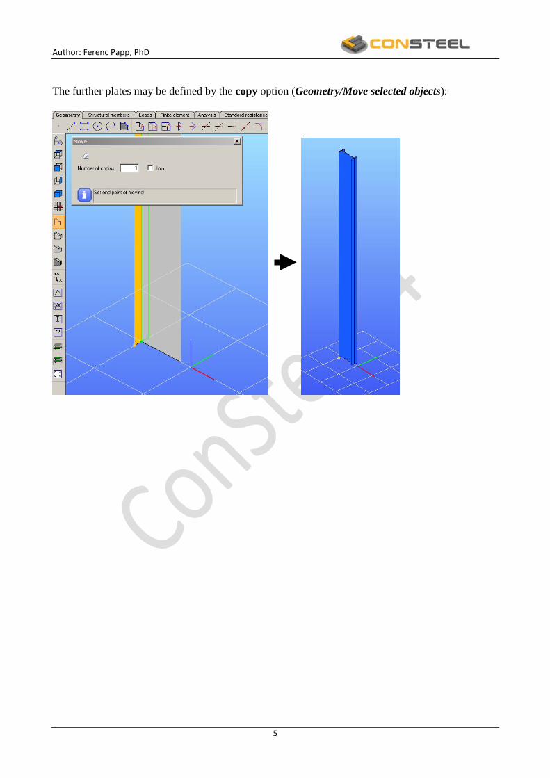
2. Supports The column connects to the bas by a moment resistance connection. The base plate and the endplate at the top of the column are modeled by one continuous plate, respectively. The 12 mm thick endplates may be defined by the Structural members/Plate option:
The rigid column base may be modeled by fix supports at the cross-section counter in X, Y and Z global directions. The upper restraints are fix in X and Y global directions. The supports may be defined by the Structural members/Point support option:

Author: Ferenc Papp, PhD
7
3. Design loads The design concentrated bending moment at the top of the column acts in he plane of the web. However, the 800 kNm design moment may be modeled by two 1000 kN concentrated forces which act in the web-flange intersection points (the distance between the points is 0,8 m). The forces can be defined by the Loads/Point load option:

Author: Ferenc Papp, PhD
8
4. Stability analysis (load amplifier: 1,crα ) The stability analysis of the structural member may be performed by the general method. The critical load amplifier is equal to the first eigenvalue which indicates lateral torsional buckling mode. The steps of the procedure are the following:
• definition of the type of the finite elements • definition of the dimension of the finite elements • mesh generation and analysis (calculation) • evaluation of the result
Definition of the type of the finite elements For stability analysis rectangular shell element and “ConSteel” mesh generation may be chosen (use the Finite element/Quadrilateral mesh option):
Definition of the dimension of the finite elements The dimension of the finite elements is the property of the plate structural element. The dimension defines the maximum length of the edges of the applied finite elements. It is suggested using same

Author: Ferenc Papp, PhD
9
dimension for all the shell elements of the mesh. To do this we select all the shell elements, open the Plate member (9) subtable and rewrite the Finite element size parameter (the new definition – 50 mm - should be activated, for example, by a mouse action on another box):
Mesh generation and analysis (calculation) To generate the finite element mesh for the structural member we select the Finite element/Create finite element mesh option:

Author: Ferenc Papp, PhD
10
The global critical load amplifier is equal to the first eigenvalue which indicates lateral torsional buckling mode. The number of eigenvalues can be defined by the Analysis/Set analysis parameters/Number of buckling modes option (for example 6 modes are required):

Author: Ferenc Papp, PhD
11
At the end of the analysis the deformed geometry of the structural model appearson the 3D window:
Evaluation of the result The critical load amplifier is available by the Analysis/Buckling/Eigenvalues option:

Author: Ferenc Papp, PhD
12
The critical load amplifier which causes lateral torsional buckling mode is 63,21,cr =α . 5. Wall beams The wall beam is made from RHS 200x100x4 hollow section, and is modeled by beam finite element. The hollow section should be read into the section module by use the Structural members/Section administration option. The wall beam is placed at the middle cross-section of the structural member. Therefore, the design raster may be specified with 2 x 6000 mm width and its centre is moved into the appropriate point of the vertical edge of the web plate:
It is assumed that the wall beam is continuous and the connection between the beam and the column is rigid. The beam is modeled with two beam members by use of the Structural members/Beam option:

Author: Ferenc Papp, PhD
13
The ends of the wall beam are supported in directions (X,Y and Z) and rotation about its axis (YY):

Author: Ferenc Papp, PhD
14
6. Stability analysis (load amplifier:
2cr ,α ) The flange of the structural meber is supported by the wall beam. The stability analysis may be carried out following Step 4. The buckling mode and the critical load amplifier are the following:
80022cr ,, =α

Author: Ferenc Papp, PhD
15
It can be seen that the effect of the wall beam to the critical load is not significant, because the wall beam supports the tension flange:
0641632802
1cr
2cr ,,,
,
, ==αα
7. Stiff restraint support The effect of the wall beam to the stability of the member may be significant, if the compression flange is connected to the wall beam with supporting bars (stiff restraint support). The relatively small SHS 60x3 bars may be placed horizontally by at about 45 degrees. The bars can be connected to the points of the beam located 1000 mm from the column (for this we divide the beam to 2x6 equal parts):
8. Stability analysis (load amplifier: 3,crα ) The compression flange of the structural member is supported by the wall beams. The stability analysis may be carried out following Step 4. The buckling mode and the critical load amplifier are given as following:
0353cr ,, =α

Author: Ferenc Papp, PhD
16
The buckling mode indicates lateral torsional buckling of the column in interaction with local web plate buckling. It can be seen that the effect of the stiff restraint to the critical load is significant (the beam supports the “compression” flange):
9131632035
1cr
3cr ,,,
,
, ==αα

Author: Ferenc Papp, PhD
17
9. Equivalent column model The above buckling mode indicates that the stiff restraint (wall beam and support bars) does not allow the column section to rotate around the member axis. However, the equivalent model of the member may be the upper part which is assumed as a simple two supported member: 10. Stability analysis (load ampélifier: 4,crα ) The stability analysis of the equivalent member gives the following buckling mode and critical load amplifier:
8244cr ,, =α

Author: Ferenc Papp, PhD
18
The buckling mode indicates the lateral torsional buckling of the upper part of the member. The calculated critical load amplifier is very close to the result of the more complex shell model:
9580035824
3cr
4cr ,,,
,
, ==αα
However, the conclusion of this example is the following: the stiff restraint of the member (support of the compression flange) is sufficient, and consequently the equivalent model gives adequate result for the stability analysis of the structural member. Summary The critical load amplifiers given by different models are summarized in the following table:
Model
(i=1,2,3,4)
Critical load amplifier
icr ,α Ratio of critical load
amplifiers
1cr
icr
,
,
αα
1. Simple column 2,63 1,000 2. Column supported at tensioned flange 2,80 1,065 3. Column supported at compressed flange 5,03 1,913 4. Equivalent column 4,82 1,830