EFFECT OF HEAT TREATMENT AND CROSS SECTION ON THE ...
12
Uludağ University Journal of The Faculty of Engineering, Vol. 24, No. 2, 2019 RESARCH DOI: 10.17482/uumfd.477569 477 EFFECT OF HEAT TREATMENT AND CROSS SECTION ON THE CRASHWORTHINESS OF 51CRV4 SPRING STEEL Çiğdem DİNDAR * Hüseyin BEYTÜT ** Selçuk KARAGÖZ * Received: 01.11.2018 ; revised: 17.05.2019 ; accepted: 22.07.2019 Abstract: In this study, 51CrV4 spring steel was used as a crash box material and its crashworthiness was investigated under axial dynamic loading. Crash boxes with cylinder and square geometries were designed in SolidWorks and crash analyses were performed by using RADIOSS/explicit and nonlinear Finite Element (FE) codes. In addition, 51CrV4 spring steel was subjected to three different heat treatments and their mechanical properties were determined by tensile and hardness tests. The crashworthiness of crash box was evaluated taking into account the energy absorption (EA), peak crushing force (PCF), mean crushing force (MCF) and crash force efficiency (CFE). Since the crash boxes had equal mass, their EA rates are equal to specific energy absorption (SEA) rates. It has been observed that heat treatment and cross-section geometry have a serious impact on crashworthiness. Keywords: Crash box, Thin-Walled Tubes, Crashworthiness, Mechanical Strength 51CrV4 Yay Çeliğinde Isıl İşlem ve Kesit Geometrisinin Çarpışma Dayanıklılığı Üzerine Etkisi Öz: Bu çalışmada, 51CrV4 yay çeliği çarpışma kutusu malzemesi olarak kullanılmış ve çarpışma dayanıklılığı araştırılmıştır. Kare ve silindir kesit geometrisine sahip çarpışma kutuları SolidWorks programında tasarlanmış ve RADIOSS açık zaman entegrasyon yöntemi ve lineer olmayan sonlu elemanlar kodları ile çarpışma analizleri gerçekleştirilmiştir. Buna ek olarak, 51CrV4 çelik malzemesi 3 farklı ısıl işleme maruz bırakılarak mekanik özellikleri çekme ve sertlik testleri ile belirlenmiştir. Belirlenen mekanik özelliklere sahip yapının çarpışma dayanıklılığı, emilen enerji, maksimum çarpışma kuvveti, ortalama çarpışma kuvveti, çarpışma kuvveti verimi dikkate alınarak değerlendirilmiştir. Çarpışma kutularının kütleleri eşit olduğundan emilen enerji oranları özgül enerji emilim oranlarına eşittir. Isıl işlem uygulamasının ve kesit geometrisinin çarpışma dayanıklılığı üzerinde ciddi bir etkisi olduğu gözlemlenmiştir. Anahtar Kelimeler: Çarpışma Kutusu, İnce-Cidarlı Tüpler, Çarpışma Dayanıklılığı, Mekanik Dayanım, 1. INTRODUCTION With the increase in the number of vehicle in our country and in the world, accident rates are increasing. This situation forced automotive manufacturers to take new measures. Many security systems have been developed by automotive designers in order to ensure safe transportation of vehicles in traffic. These security systems can be examined under two main * Bursa Technical University, Faculty of Engineering and Natural Sciences, Mechanical Engineering, 16330. Yıldırım, Bursa * * Bitlis Eren University, Faculty of Engineering and Architecture, Mechanical Engineering, 13100. Merkez, Bitlis Corresponding Author: Selçuk KARAGÖZ ([email protected])
Transcript of EFFECT OF HEAT TREATMENT AND CROSS SECTION ON THE ...

Uludağ University Journal of The Faculty of Engineering, Vol. 24, No. 2, 2019 RESARCH DOI: 10.17482/uumfd.477569
477
EFFECT OF HEAT TREATMENT AND CROSS SECTION ON THE
CRASHWORTHINESS OF 51CRV4 SPRING STEEL
Çiğdem DİNDAR *
Hüseyin BEYTÜT **
Selçuk KARAGÖZ *
Received: 01.11.2018 ; revised: 17.05.2019 ; accepted: 22.07.2019
Abstract: In this study, 51CrV4 spring steel was used as a crash box material and its crashworthiness
was investigated under axial dynamic loading. Crash boxes with cylinder and square geometries were
designed in SolidWorks and crash analyses were performed by using RADIOSS/explicit and nonlinear
Finite Element (FE) codes. In addition, 51CrV4 spring steel was subjected to three different heat
treatments and their mechanical properties were determined by tensile and hardness tests. The
crashworthiness of crash box was evaluated taking into account the energy absorption (EA), peak
crushing force (PCF), mean crushing force (MCF) and crash force efficiency (CFE). Since the crash
boxes had equal mass, their EA rates are equal to specific energy absorption (SEA) rates. It has been
observed that heat treatment and cross-section geometry have a serious impact on crashworthiness.
Keywords: Crash box, Thin-Walled Tubes, Crashworthiness, Mechanical Strength
51CrV4 Yay Çeliğinde Isıl İşlem ve Kesit Geometrisinin Çarpışma Dayanıklılığı Üzerine Etkisi
Öz: Bu çalışmada, 51CrV4 yay çeliği çarpışma kutusu malzemesi olarak kullanılmış ve çarpışma
dayanıklılığı araştırılmıştır. Kare ve silindir kesit geometrisine sahip çarpışma kutuları SolidWorks
programında tasarlanmış ve RADIOSS açık zaman entegrasyon yöntemi ve lineer olmayan sonlu
elemanlar kodları ile çarpışma analizleri gerçekleştirilmiştir. Buna ek olarak, 51CrV4 çelik malzemesi 3
farklı ısıl işleme maruz bırakılarak mekanik özellikleri çekme ve sertlik testleri ile belirlenmiştir.
Belirlenen mekanik özelliklere sahip yapının çarpışma dayanıklılığı, emilen enerji, maksimum çarpışma
kuvveti, ortalama çarpışma kuvveti, çarpışma kuvveti verimi dikkate alınarak değerlendirilmiştir.
Çarpışma kutularının kütleleri eşit olduğundan emilen enerji oranları özgül enerji emilim oranlarına
eşittir. Isıl işlem uygulamasının ve kesit geometrisinin çarpışma dayanıklılığı üzerinde ciddi bir etkisi
olduğu gözlemlenmiştir.
Anahtar Kelimeler: Çarpışma Kutusu, İnce-Cidarlı Tüpler, Çarpışma Dayanıklılığı, Mekanik Dayanım,
1. INTRODUCTION
With the increase in the number of vehicle in our country and in the world, accident rates
are increasing. This situation forced automotive manufacturers to take new measures. Many
security systems have been developed by automotive designers in order to ensure safe
transportation of vehicles in traffic. These security systems can be examined under two main
* Bursa Technical University, Faculty of Engineering and Natural Sciences, Mechanical Engineering, 16330.
Yıldırım, Bursa * * Bitlis Eren University, Faculty of Engineering and Architecture, Mechanical Engineering, 13100. Merkez, Bitlis
Corresponding Author: Selçuk KARAGÖZ ([email protected])

Dindar Ç.,Beytüt H.,Karagöz S.:Heat Treatment and Cross Section on the Crashworthiness of 51CRV4
478
groups as active and passive security systems. While active safety systems reduce the likelihood
of an accident happen, passive safety systems allow passengers to circumvent the accident with
minimum damage in the event of accident.
Crash box is one of the most important passive safety system member. Therefore, the design
of the crash boxes and the choice of materials is extremely critical for passengers and goods
safety (Öztürk and Kaya, 2008). The following Figure 1 shows the crash boxes and bumper
beam assemble.
Figure 1:
The assembly of crash box (N Nasir, 2015)
In case of frontal crash accident, the crash box is expected to be collapsed with absorbing
kinetic energy of vehicle by undergo plastic deformation, especially at medium and low speeds.
In this way, passengers, cargo and critical parts of the vehicle will avoid the accident with
minimum damage (Nakazawa at. al., 2005).
Thin-walled structures (TWTs) have a wide range of use in automobiles due to their high
energy absorption, easy formability and low cost. Many studies have been focus on increase
specific energy absorption of this structure (Xie at. al., 2017; Yıldız at. al., 2016; Karagöz and
Yıldız, 2017). The effects of cross-section on crashworthiness have been investigated by using
geometries such as square, cylinder, hexagons (Alavi and Parsapour, 2014; Yao at. al., 2017;
Liang at. al., 2017). Since the mechanical properties of the materials change by heat treatment
applications, it is expected that the crashworthiness of structure will change. In the literature,
studies have been carried out on how crashworthiness of the structure changed after heat
treatment (Bambach at. al., 2016; Campana and Pilone, 2009; Millett at. al., 2004; Conrads at.
Al., 2017).
While determining the crashworthiness of energy absorbers, energy absorption, specific
energy absorption, peak crushing force, mean crushing force, and crush for efficiency should be
taken into consideration (Tran at. al., 2015).
1.1 Energy Absorption (EA)
What is expected from the crash box is to convert the kinetic energy into plastic
deformation energy. EA could be found by the area under the crash load versus displacement
curve (Equation 1).
∫
(1)
Where; P(x) is the axial load, d is the crash distance

Uludağ University Journal of The Faculty of Engineering, Vol. 24, No. 2, 2019
479
1.2 Specific Energy Absorption (SEA)
Specific energy absorption (SEA) is used to indicate the amount of energy absorbed per unit
mass of the crash box (Equation 2). So it is important for lightweight design.
(2)
Where; m is the mass of the crash box.
1.3 Peak Crushing Force (PCF)
Studies have shown that the PCF ( ) is generally occurs at the first reaction force
(TrongHhan at. Al., 2015). It was observed that the PCF was reduced by adding trigger
mechanism (hole, groove etc.) to the crash box (Nasir at. al., 2017).
1.4 Mean Crushing Force (MCF)
The MCF ( ) is obtained by dividing EA to the crash distance (Equation 3). In terms of
energy absorption, crash loads should be stable and close to the MCF.
(3)
1.5 Crush Force Efficiency (CFE)
The CFE ( ) is found by the ratio of the MCF to the PCF (Equation 4). Since it depends on
both the EA and the PCF, it is an important parameter in evaluating the crashworthiness of the
structure.
(4)
2. MATERIAL AND METHOD
In this study, 51CrV4 steel was used for the material of crash box. 51CrV4 steel is a spring
steel material from the medium carbon steel group. The carbon ratios of the spring steels are the
higher than the structural steels, and they are also lower than the carbon ratios of the tool steels.
It is important that the ratio of the yield limit to the tensile strength is high and the modulus of
elasticity is stable in spring steels.
51CrV4 can be easily heat treated such as austenitizing, quenching and then tempering. In
this paper, it has been investigated how to effect on the crashworthiness of material properties
such as ductility and strength that can be changed by heat treatment.
2.1 Heat treatment Application
Heat treatment was applied to the material in order to observe both differences the plastic
deforming ability and the strength values of spring steel 51CrV4. Thus, the changes in the
mechanical properties of the materials by heat treatment were examined and these new
mechanical properties were used in the crash analyses.
In the heat treatment process, the tempering temperature was changed. In addition, the
austenitizing temperature and duration, cooling temperature in oil were kept constant. The heat
treatment application values have showed in Table 1.

Dindar Ç.,Beytüt H.,Karagöz S.:Heat Treatment and Cross Section on the Crashworthiness of 51CRV4
480
Table 1. Heat treatment application parameters
Sample No Austenitizing
Temperature
/Duration
Cooling in Oil
Temperature
Tempering
Temperature
/Duration
Sample 1 850 C 1 hour 80 C 400 C 75min
Sample 2 850 C 1 hour 80 C 440 C /75min
Sample 3 850 C 1 hour 80 C 480 C 75min
Primarily, the samples were preheated at 400 ° C for 1 hour in tempering furnaces. When
the materials at room temperature had been put to the curing oven placed at temperatures
between 850 - 950°C are heated suddenly, the dimensional tolerance change (waste) may be
higher than the prescribed values. In addition, the materials can be cracked due to thermal shock
and high stress in the curing oven. The base purpose of pre-heating process is to prevent all
these predictable errors like thermal shock and high stress.
In preheating processes performed at temperatures higher than 400°C, oxide layer or
decarburisation in surface may occur due to the atmosphere-free furnace. Therefore,
temperatures in the preheating are generally kept between 300 and 400°C.
After preheating process, austenitization and hardening application of heat treatment had
been performed. The austenitization process is applied on the Fe – Fe3C diagram at
approximately 30 - 50 °C above the A3 curve. At the end of the process, austenite phase (face
centred cubic structure) is formed in the material. Following the austenitizing process, the steels
cooled in a normal air conditions have been normalized. Thus, the material is provided a thinner
and homogeneous structure.
The material can be hardened in the result of cooling with air or N2 and with oil, water or
polymer cooling according to the amount of carbon and alloying elements of the steel. The steel
in the face centred cubic (FCC) phase is transformed into body centred tetragonal (BCT)
martensite phase without diffusion by the sudden cooling process.
In this study, austenitization process was applied to the low alloy steel 51CrV4 at 850°C
for 1 hour and then cooled in oil at 80°C. After cooling process in the oil, martensite phase was
formed and hardness values of 60 HRC were detected subsequent to the hardness measurement.
Samples dipped to the cooling oil were washed with special chemicals at temperatures
among 60 - 80°C. Thus, the oil layers on the surface of the material were cleaned.
In a result of the oil hardening process, the steel in the martensite crystal structure is a very
fragile. In order to increase the toughness of the material and to remove the stresses occurring in
the structure after the phase transformation, tempering process is applied. Tempering process
was carried out at 400°C, 440°C and 480°C for 75 min. As a result of this tempering process,
the tension of the material was removed, toughness and ductility values are increased, while the
strength and hardness values decrease.
2.2 Mechanical Properties
The most commonly used tests for determining the mechanical strength of materials are
hardness and tensile tests. Mechanical properties such as yield strength, tensile strength,
modulus of elasticity, elongation at break, fracture energy can be determined by tensile test
while hardness measurement provide information about hardness of material. While
measurements is performed, it is very important that the precision measurement of data. The
samples of the tensile test with each similar parameter has been repeated by three times due to
provide the sensitivity of the accuracy of the test. In addition, the hardness of samples which
were applied heat treatment had been measured by Rockwell hardness measuring device.
The steels manufactured from 51CrV4 material that we studied in this paper are preferred
commonly for anti-roll bar. These steels generally are used in the range 42-48 HRC hardness.
Uludağ University Journal of The Faculty of Engineering, Vol. 24, No. 2, 2019
481
The performance expected from anti-roll bar by 51CrV4 is high yield strength, the material can
be sprung and not broken in a short time. However, the fatigue performance of the material is
also extremely important. Therefore, when hardness groups are selected in the study, it is
considered that the material will be broken when the material is crushed at very low or very
high hardness values are reached.
According to results of heat treatment, for the purpose of determine the mechanical
properties of material at various hardness values, the samples used in the range 42 - 48 HRC
were separated into three hardness groups and the hardness measure tests were carried out.
Hardness measurement results are given in Table 2.
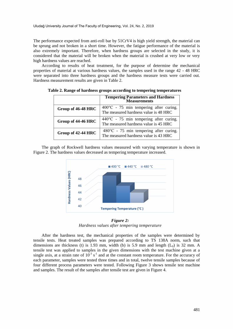
Table 2. Range of hardness groups according to tempering temperatures
Tempering Parameters and Hardness Measurements
Group of 46-48 HRC 400°C - 75 min tempering after curing.
The measured hardness value is 48 HRC
Group of 44-46 HRC 440°C - 75 min tempering after curing.
The measured hardness value is 45 HRC
Group of 42-44 HRC 480°C - 75 min tempering after curing.
The measured hardness value is 43 HRC
The graph of Rockwell hardness values measured with varying temperature is shown in
Figure 2. The hardness values decreased as tempering temperature increased.
Figure 2: Hardness values after tempering temperature
After the hardness test, the mechanical properties of the samples were determined by
tensile tests. Heat treated samples was prepared according to TS 138A norm, such that
dimensions are thickness (t) is 1.93 mm, width (b) is 5.9 mm and length (L0) is 32 mm. A
tensile test was applied to samples in the given dimensions with the test machine given at a
single axis, at a strain rate of 10-3
s-1
and at the constant room temperature. For the accuracy of
each parameter, samples were tested three times and in total, twelve tensile samples because of
four different process parameters were tested. Following Figure 3 shows tensile test machine
and samples. The result of the samples after tensile test are given in Figure 4.
40
42
44
46
48
Har
dn
ess
Val
ue
s (H
RC
)
Tempering Temperature (°C )
400 °C 440 °C 480 °C

Dindar Ç.,Beytüt H.,Karagöz S.:Heat Treatment and Cross Section on the Crashworthiness of 51CRV4
482
Figure 3: The tensile test machine and the samples
Figure 4:
True stress-strain curve after heat-treatment
2.3 Crash Analysis
For crash analysis, design of the crash box was carried out after the mechanical properties
of the heat-treated material to be used in the analysis were determined by hardness and tensile
tests. Crash box to be used in analysis is designed in SolidWorks software. Pre-processing was
performed by using HyperCrash, RADIOSS/explicit was used as a solver and for post-
processing HyperGraph and HyperView were utilized. Process methodology of crash analysis
has been shown in Figure 5.
0
200
400
600
800
1000
1200
1400
1600
1800
0 2 4 6 8 10 12 14 16 18 20 22
Str
ess
(MP
a)
Strain (%)
480°C, 43 HRC 440°C, 45 HRC
400°C , 48 HRC Without heat-treatment

Uludağ University Journal of The Faculty of Engineering, Vol. 24, No. 2, 2019
483
Figure 5:
Process methodology of the crash analysis
Crash analyses have been carried out in two different types of crash box as square and
cylindrical cross sections. The perimeter of the cross sections for cylindrical and square crash
boxes were 360 mm, the length is 130 mm and wall thickness is 1.2 mm. In this way, the masses
of the crash boxes are ensured to be equal. 3 mm x 3 mm mesh size was utilized. The velocity
of the was preferred 13.89 m/s that is taken from EURO NCAP protocol and 600 kg mass was
added to end of the crash box. The total kinetic energy of the model was 57880 J. “Nodes to
Surface Contact” definition was utilized with 0.2 friction coefficient between the crash box and
rigid wall and self-contact algorithm is used for avoiding interpenetration between crash box
surface during folding, provided by RADIOSS. For avoiding hourglass energy 5 integration
point used through the thickness. The crash box is restricted to all degrees of freedom except for
the axis of speed x.
Figure 6: Finite element model of crash box before crash analysis

Dindar Ç.,Beytüt H.,Karagöz S.:Heat Treatment and Cross Section on the Crashworthiness of 51CRV4
484
3. RESULTS AND DISCUSSION
Explicit and non-linear analyses of the crash boxes were performed and the crash force-
displacement and absorbed energy-displacement curves were obtained (Figure 7 and 8).
Figure 7: Crash load versus displacement curve for cylinder tube
Figure 8:
Crash load versus displacement curves for square tube
As shown in Figure 7 and 8, the crash loads of the cylindrical crash box were more stable
than the square crash box. Since the strength of the material was increased after the heat
treatment application, the first folding was occurred difficult and therefore the PCF was higher
for both geometries. While The PCF of the non-heat-treated crash boxes were the lowest, the
crash boxes subjected to heat treatment at 400°C were the highest. Absorbing energy versus
displacement curve of cylindrical and square crash boxes were given in Figure 9 and Figure 10,
respectively.
0
100
200
300
400
500
600
700
800
0 10 20 30 40 50 60 70 80 90 100
Cra
sh L
oad
(kN
)
Displacement (mm)
480°C, 43 HRC
440°C, 45 HRC
400°C, 48 HRC
Without heat-treatment
0
100
200
300
400
500
600
700
800
0 10 20 30 40 50 60 70 80 90 100
Cra
sh L
oad
(kN
)
Displacement (mm)
480°C , 43 HRC
440°C, 45 HRC
400°C, 48 HRC
Without heat-treatment

Uludağ University Journal of The Faculty of Engineering, Vol. 24, No. 2, 2019
485
Figure 9: Absorbing energy-displacement graph for cylinder tube
Figure 10:
Absorbing energy-displacement graph for square tube
The impact response of the cylindrical and square crash boxes after heat treatment are
given in Table 3. Since The crash boxes had equal mass, their energy absorption rates equal to
their specific energy absorption. In all cases, EA, MCF and CFE of the cylindrical crash boxes
were higher than the square crash boxes. When the crashworthiness of the crash boxes was
evaluated in terms of CFE, the best result was obtained at 400°C heat-treated cylindrical crash
box, while the worst result obtained at 440°C heat-treated square crash box. With parallel to
literature, crashworthiness of cylindrical crash box was better than square crash box.
Table 3. Impact response of the cylindrical and square crash boxes
Condition Without heat treatment
AE (J) PCF (kN) MCF (kN) CFE
400°C heat treatment
AE (J) PCF (kN) MCF (kN) CFE
Cylinder 12671 347 126.9 0.366 27928 725 279.9 0.386
Square 11648 353 116.7 0.33 22482 733 225.2 0.307
Condition 440°C heat treatment
AE (J) PCF (kN) MCF (kN) CFE
480°C heat treatment
AE (J) PCF (kN) MCF (kN) CFE
Cylinder 25426 713 254.82 0.357 25375 694 254.31 0.366
Square 19869 719 199.03 0.277 19464 701 194.97 0.278
0
5000
10000
15000
20000
25000
30000
0 10 20 30 40 50 60 70 80 90 100
Ab
sorb
ing
Ene
rgy
(J)
Displacement (mm)
480°C, 43 HRC
440°C, 45 HRC
400°C, 48 HRC
Without heat-treatment
0
5000
10000
15000
20000
25000
30000
0 10 20 30 40 50 60 70 80 90 100
Ab
sorb
ing
Ene
rgy
(J)
Displacement (mm)
480°C, 43 HRC
440°C, 45 HRC
400°C, 48 HRC
Without heat-treatment

Dindar Ç.,Beytüt H.,Karagöz S.:Heat Treatment and Cross Section on the Crashworthiness of 51CRV4
486
CONCLUSION
In this study, the effect of heat treatment on crashworthiness of 51CRV4 spring steel was
investigated. Therefore, the 51CRV4 spring steel has been subjected to three different heat
treatments (400°C 440°C and 480°C). After heat treatment the mechanical properties of heat-
treated 51CRV4 spring steel were determined by tensile and hardness tests. In addition,
cylindrical and square collision boxes were designed to investigate the impact of cross-section
on crashworthiness. Accordingly, the following conclusions can be drawn.
Since the mechanical properties of 51CRV4 spring steel changed after the heat treatment,
the crash performance also changed. It has been concluded that the application of heat
treatment has a serious effect on the crash performance.
The EA of the cylindrical box which subjected to the heat treatment at 400°C increased by
120.4% and PCF increased by 108.9%. For square crash box, EA increased by 93% and
PCF increased by 107.6%
The cross-section had a serious effect on the crash performance. The crashworthiness of the
cylindrical crash box was better for all cases.
In all cases, the PCF of the cylindrical crash box was lower than the square crash box and
subsequent crash loads were. more stable
ACKNOWLEDGEMENTS
Thanks to the ÖNERLER Company for the heat treatment applications.
REFERENCES
1. Alavi Nia, A. and Parsapour, M. (2014). Comparative analysis of energy absorption
capacity of simple and multi-cell thin-walled tubes with triangular, square, hexagonal and
octagonal sections. Thin-Walled Structures, 74, 155-165. doi:10.1016/j.tws.2013.10.005.
2. Bambach, M., Conrads, L., Daamen, M., Güvenç, O, and Hirt, G. (2016). Enhancing the
crashworthiness of high-manganese steel by strain-hardening engineering, and tailored
folding by local heat-treatment. Materials & Design, 110, 157-168.
doi:10.1016/j.matdes.2016.07.065.
3. Campana, F. and Pilone, D. (2009). Effect of heat treatments on the mechanical behaviour
of aluminium alloy foams. Scripta Materialia, 60(8), 679-682.
doi:10.1016/j.scriptamat.2008.12.045.
4. Conrads, L., Conrad, L. and Hirt G. (2017). Increasing the energy absorption capacity of
structural components made of low alloy steel by combining strain hardening and local heat
treatment. International Conference on the Technology of Plasticity, ICTP 2017, 17-22
September 2017, Cambridge, United Kingdom. doi: 10.1016/j.proeng.2017.10.771
5. Karagöz, S. and Yıldız, A. R. (2017). Comparison of recent metaheuristic algorithms for
crashworthiness optimisation of vehicle thin-walled tubes considering sheet metal forming
effects. Int. J. Vehicle Design, Vol. 73, Nos. 1/2/3, 2017. doi:10.1504/IJVD.2017.082593
6. Liang, C., Wang, C. J., Nguyen, V. B., English, M. and Mynors, D. (2017). Experimental
and numerical study on crashworthiness of cold-formed dimpled steel columns. Thin-
Walled Structures, 112, 83-91. doi:10.1016/j.tws.2016.12.020.
7. Millett, J., Bourne, N. and Edwards, M. (2004). The effect of heat treatment on the shock
induced mechanical properties of the aluminium alloy, 7017. Scripta Materialia, 51(10),
967-971. doi:10.1016/j.scriptamat.2004.07.020.

Uludağ University Journal of The Faculty of Engineering, Vol. 24, No. 2, 2019
487
8. Nakazawa, Y., Tamura, K., Yoshida, M., Tagaki, K. and Kano, M. (2005) Development of
crash-box for passenger car with high capability for energy absorption, VIII. International
Conference on Computational Plasticity, Barcelona, Spain.
9. N Nasir, H., Srinivasa Prakash, R., Yendluri V. and Daseswara, R. (2017). Comparative
Study Of Trigger Configuration For Enhancement Of Crashworthiness Of Automobile
Crash Box Subjected To Axial Impact Loading. Procedia Engineering, 173, 1390-1398.
doi: 10.1016/j.proeng.2016.12.198
10. N Nasir, H. (2015). Automobile Crash Box Design Improvement Using HyperStudy. India
Altair Technology Conference. Hyundai Motor India Engineering Pvt. Ltd. Survey No.
5/2,5/3. Opp. Hitech City Railway Station, Izzatnagar, Hyd – 84.
11. Öztürk, İ. and Kaya, N. (2008). Otomobil Ön Tampon Çarpişma Analizi Ve Optimizasyon,
Uludağ Üniversitesi Mühendislik-Mimarlık Fakültesi Dergisi, Cilt 13, Sayı 1.
12. Tran, T., Hou, S., Han, X. and Chau, M. (2015). Crushing analysis and numerical
optimization of angle element structures under axial impact loading. Composite Structures,
119, 422-435. doi:10.1016/j.compstruct.2014.09.019.
13. Xie, S., Yang, W., Wang, N. and Li, H. (2017). Crashworthiness analysis of multi-cell
square tubes under axial loads. International Journal of Mechanical Sciences, 121, 106-118.
doi:10.1016/j.ijmecsci.2016.12.005.
14. Yao, S., Xing, Y. and Zhao, K. (2017). Crashworthiness analysis and multiobjective
optimization for circular tubes with functionally graded thickness under multiple loading
angles. Advances in Mechanical Engineering, 9(4). doi:10.1177/1687814017696660.
15. Yıldız, A. R., Kurtuluş, E., Demirci, E., Yıldız, B. S. and Karagöz, S. (2016).
Optimization of thin-wall structures using hybrid gravitational search and Nelder-Mead
algorithm. Materials Testing, Vol. 58, No. 1, pp. 75-78. https://doi.org/10.3139/120.110823.

488