Effect of Geometric Configuration of Quadratic Folded ... · Effect of Geometric Configuration of...
9
Journal of American Science 2010;6(7) http://www.americanscience.org [email protected] 318 Effect of Geometric Configuration of Quadratic Folded Plate Roofing Systems on Their Static and Dynamic Behavior. 1 H. Elkady and 2 A. Hasan 1 Civil Engineering Dept., National Research Center, Cairo , 2 Beni-suef University, Egypt. Abstract: Some researchers proposed different analytical methods for presenting boundary conditions, and stiffeners effect in analytical solutions of folded plate slabs. This study investigates the effect of each of these factors to review the previous approximations range of validity for longer spans Quadratic Folded Plate (Q.F.P) slabs. The chosen elements are: Stiffness of end diaphragms, intermediate beams stiffness, and folded plates rise (height). Besides, the effectiveness of increasing the folded plates’ thickness on the structural behavior of the system was investigated as well. Hence, the impact of such variance on the static and dynamic behavior of the system is studied. All previous parameters were applied on systems with three different spans 14, 20 and 26 meters. In order to achieve the previous objectives, 3-D Finite Elements Models (F.E.M) were adopted.to perform linear static analysis on the investigated systems, and the effect of each of the above mentioned parameters on deflections and stresses was studied and analyzed. The studied Q,F,P. rises varied from 90 cm to 180 cm. This doubling of rise reduced the roof deflection by 60% Increasing Q.F.P slab thickness from 8 to 12 cm limited this reduction in deflection to 15%. Stiffness of intermediate beams was another investigated factor, its original stiffness was increased up to six time. Tripling the intermediate beams original stiffness resulted in reducing slabs deflections by 17%. These parameters resulted in a similar trend in reduction of intermediate beams bending moments. As for reduction in end diaphragm bending moments due to changing Q.F.P rise, it reached 40% decrease on increasing the rise from 90 to 180 cm. Three Dimensional dynamic modal analyses were performed as well. The effect of different diaphragms, intermediate beams, and spans on the fundamental modes was investigated. From modal analysis, it was concluded that increasing the span from 14 to 20 meters did not have significant effect on the fundamental frequencies. On the other hand the 26 meters natural frequencies were lower by 27% from both spans. Increasing the roof rise from 90 to 180 cm increased the natural frequencies by 25%, this can be attributed to the increase in the stiffness of the system. Finally, the obtained results confirmed on the diffiecency in design that can result from approximate end conditions, or neglecting stiffners effect in analytical modeling, especially for Q.F.P. slabs with long spans. Consequently, elaborate numerical analysis is recommended in dealing with longer spans Q.F.P systems, as the geometric properties of each contributing element had obvious effect on the overall performance of the system. It is also concluded that folded plate rise is the most effective in the investigated parameters, while difference in folded plate thickness had the lowest effect on both static and dynamic behavior of the investigated system. [Journal of American Science 2010;6(7):318-326]. (ISSN: 1545-1003). Key Words: Folded plates, height, end diaphragm, stiffness, and free vibrations. 1. Introduction Folded plates are considered one of the very useful basic systems in engineering. Their applications can be found in various branches of engineering, such as in roofs, sandwich plate cores and cooling towers, etc. They are lightweight, easy to form, economical, and have much higher load carrying capacities than flat plates, which ensures their popularity and has attracted constant research interest since they were introduced. Early researchers solved folded plate problems approximately with the beam method or the theory that neglected relative joint displacement. However, these two methods meet difficulties in dealing with generalized folded plate problems. Computational approaches and numerical methods for folded plates offer more precise solutions. The methods of interest include finite strip methods [1-3], the combined boundary element-transfer matrix method [4], and finite element methods (FEM) [5-8]. From these methods, the FEMs are the most convenient because they can be applied to analyze large complex structures, and all kinds of boundary conditions and loadings can be easily implemented. Hence, almost all commercial software for structural analysis uses FEMs. Q.F.P roofs is one of the most commonly used types of such roofing systems. Hence, it was chosen for this study. The presented study on the effect of geometric configuration of the systems main structural elements utilizes numerical analysis. Linear Static Three Dimensional F.E. analysis was performed. Effect of each parameter on slab deflection, end diaphragms moments, and intermediate beams maximum moments were reported. Hence, effect of applying real boundary conditions, and stiffeners is evaluated compared to
-
Upload
phungquynh -
Category
Documents
-
view
223 -
download
0
Transcript of Effect of Geometric Configuration of Quadratic Folded ... · Effect of Geometric Configuration of...
Journal of American Science 2010;6(7)
http://www.americanscience.org [email protected] 318
Effect of Geometric Configuration of Quadratic Folded Plate Roofing Systems on Their Static and Dynamic Behavior.
1H. Elkady and 2A. Hasan
1Civil Engineering Dept., National Research Center, Cairo, 2 Beni-suef University, Egypt. Abstract: Some researchers proposed different analytical methods for presenting boundary conditions, and stiffeners effect in analytical solutions of folded plate slabs. This study investigates the effect of each of these factors to review the previous approximations range of validity for longer spans Quadratic Folded Plate (Q.F.P) slabs. The chosen elements are: Stiffness of end diaphragms, intermediate beams stiffness, and folded plates rise (height). Besides, the effectiveness of increasing the folded plates’ thickness on the structural behavior of the system was investigated as well. Hence, the impact of such variance on the static and dynamic behavior of the system is studied. All previous parameters were applied on systems with three different spans 14, 20 and 26 meters. In order to achieve the previous objectives, 3-D Finite Elements Models (F.E.M) were adopted.to perform linear static analysis on the investigated systems, and the effect of each of the above mentioned parameters on deflections and stresses was studied and analyzed. The studied Q,F,P. rises varied from 90 cm to 180 cm. This doubling of rise reduced the roof deflection by 60% Increasing Q.F.P slab thickness from 8 to 12 cm limited this reduction in deflection to 15%. Stiffness of intermediate beams was another investigated factor, its original stiffness was increased up to six time. Tripling the intermediate beams original stiffness resulted in reducing slabs deflections by 17%. These parameters resulted in a similar trend in reduction of intermediate beams bending moments. As for reduction in end diaphragm bending moments due to changing Q.F.P rise, it reached 40% decrease on increasing the rise from 90 to 180 cm. Three Dimensional dynamic modal analyses were performed as well. The effect of different diaphragms, intermediate beams, and spans on the fundamental modes was investigated. From modal analysis, it was concluded that increasing the span from 14 to 20 meters did not have significant effect on the fundamental frequencies. On the other hand the 26 meters natural frequencies were lower by 27% from both spans. Increasing the roof rise from 90 to 180 cm increased the natural frequencies by 25%, this can be attributed to the increase in the stiffness of the system. Finally, the obtained results confirmed on the diffiecency in design that can result from approximate end conditions, or neglecting stiffners effect in analytical modeling, especially for Q.F.P. slabs with long spans. Consequently, elaborate numerical analysis is recommended in dealing with longer spans Q.F.P systems, as the geometric properties of each contributing element had obvious effect on the overall performance of the system. It is also concluded that folded plate rise is the most effective in the investigated parameters, while difference in folded plate thickness had the lowest effect on both static and dynamic behavior of the investigated system. [Journal of American Science 2010;6(7):318-326]. (ISSN: 1545-1003). Key Words: Folded plates, height, end diaphragm, stiffness, and free vibrations.
1. Introduction
Folded plates are considered one of the very useful basic systems in engineering. Their applications can be found in various branches of engineering, such as in roofs, sandwich plate cores and cooling towers, etc. They are lightweight, easy to form, economical, and have much higher load carrying capacities than flat plates, which ensures their popularity and has attracted constant research interest since they were introduced. Early researchers solved folded plate problems approximately with the beam method or the theory that neglected relative joint displacement. However, these two methods meet difficulties in dealing with generalized folded plate problems. Computational approaches and numerical methods for folded plates offer more precise solutions. The methods of interest include finite strip methods [1-3], the combined boundary element-transfer matrix method [4], and finite
element methods (FEM) [5-8]. From these methods, the FEMs are the most convenient because they can be applied to analyze large complex structures, and all kinds of boundary conditions and loadings can be easily implemented. Hence, almost all commercial software for structural analysis uses FEMs.
Q.F.P roofs is one of the most commonly used types of such roofing systems. Hence, it was chosen for this study. The presented study on the effect of geometric configuration of the systems main structural elements utilizes numerical analysis. Linear Static Three Dimensional F.E. analysis was performed. Effect of each parameter on slab deflection, end diaphragms moments, and intermediate beams maximum moments were reported. Hence, effect of applying real boundary conditions, and stiffeners is evaluated compared to

Journal of American Science 2010;6(7)
http://www.americanscience.org [email protected] 319
the accuracy of boundary conditions, and stiffeners approximation proposed in earlier literature [9,10,11]. As for free vibrations of Q.F.P slabs, most of the adopted analytical solutions uncouple the different modes of vibration, as the well known Naghdi shell equations [12,13]. These equations, when applied to plates, lead to a case where the transversal and the in plan deformation appear uncoupled.
Another analytical solution is available by Reissner–Mindlin equations [14], which are modeled by the elasticity equation, and does not depend on the thickness of the plate.
To evaluate the above mentioned approximations, and to estimate the effect of different structural elements including plates thickness, 3-D F.E. free vibration analysis was adopted in this study as well. 2. Finite Elements Analysis 2.1. Geometry and dimensions of investigated systems
All Q.F.P.slabs subjected to the presented studies had constant panels of 7.8 ms width (Fig.1a). Three different spans -14, 20, and 26 m- were investigated. A 3-D F.E. analysis was performed, in which the roof was modeled using 3-D quadratic shell elements (Fig.1b), while intermediate beams, end diaphragms, and columns were modeled as 3-D frame elements. The roof depth –or height- is referred to by the term “rise” throughout this study.
Figure 1a: Cross section dimensions of investigated
models
Figure 1b: 3-D model of investigated folded plates
panels
2.2.Static Analysis of Q.F.P System 3-D Static linear F.E.analysis was performed. applying each of the parameters under study separately. In addition to the structure own weight, an imposed static load of 150 kg/sq.cm was applied on all models, as a make up for flooring and service. Throughout the analysis, the following straining actions and deformations are monitored and compared: Deflections and stresses at different locations of the folded plate are checked, maximum bending moments at diaphragms, and intermediate beams. The tested parameters effect is given below in details: 2.2.1. Effect of end diaphragm stiffness on .Q.F.P. system 2.2.1.1. End diaphragm stiffness effect on folded slab deflections.
The first investigated parameter was the end diaphragms stiffness, and its role in deflection control of the on Q.F.P. systems for each of the three chosen spans 14,20 and 26 metres. Variation in inertia was achieved by maintaining constant depth (70 cm) and changing diaphragm width from 10 to 150 cm.
Figure.2. displays the maximum deflection for Q.F.P.slabs versus end diaphragms with different widths. The Maximum deflection of the 26 m span slab with minimum diaphragm thickness (10 cm) was 13 mm, this value was reduced to 6mm when diaphragm width increased to 150 cm. This value presents a 54% reduction in slab deflection As for the system with the shortest span (14 meters) deflection values were 1.5 and 1 mm, for the 10 ,and 150 cm width diaphragm systems repsectively, in other words reduction of 33% in slab deflection
In common practice, end diaphragms width usually rangs from 40 to 80 cm, Increasing the end diaphragm width in the 26 meters span system from 40 to 8 cm, reduced Q.F.P. maximum deflection from 10.3 mm to 9 mm (13%). As for the shortest span -14 meters- the reduction in deflection was from1.15 mm to 1.05 mm( 9%)
From the same figure it can be observed that the increase in diaphragm width over 80 cm in 14 meters span system did not enhance slab deflection. As for the 20 meters span deflection became constant when a diaphragm of 90 cm width or more is used. The slab deflection in the longest studied span -26 meters- did not reach a constant value, even on reaching an extreme diaphragm width of 1.5 meters.

Journal of American Science 2010;6(7)
http://www.americanscience.org [email protected] 320
Fig. 2: Q.F.P. slabs maximum deflection versus
different diaphragm widths.
2.2.1.2. End diaphragm stiffness effect on induced stresses inQ.F.P.slabs.
Stresses in folded slab roof are analyzed in two main directions: along the slab longitudinal axis, and perpendicular to it. Maximum compressive and tensile stresses were studied in both directions, and displayed in Figure 3.
Fig.3 (a) displays the maximum positive stresses in the Q.F.P. for the three studied spans. It can be observed that the resulting stresses in the 26 meters span are four times those in the 14 meters span slab., while the ratio of the length square –resulting from beam analysis is 3.45 times.
Increasing diaphragm width from 10 to 100 cm reduced the maximum stresses in the Q.F.P.slab of the 26 meters span system from 700 to 520 t/sq.m (25%). As for the compressive stresses (Fig3.b), the maximum variation in stresses sue to difference in end diaphragm stiffness was noticed in the 26 meters span system, as the stresses were reduced from 350 to 255 t/sq. meters (reduction of 28%) on increasing diaphragm width from 10 to 100 cms. 2.2.2.Effect of folded plate rise and intermediate beams stiffness on folded roof deflections.
Four possible rises for Q.F.P. slabs were considered in this study: 0.9, 1.2, 1.5 and, 1.8 meters. The original intermediate beams dimensions used in the study were 0.3*0.7 meters (width*depth respectively), triple (3I) and six times (6I) this stiffness was considered as well. Figure 4 gathers the effect of both: roof rise, and intermediate beams stiffnesses on slab deflection, each will be discussed separately as follows:
2.2.2.1..Effect of roof rise on the deflections of folded plate slabs with different spans.
For longest investigated span (26m) doubling folded plate depth (rise) from 0.9 m to 1.8 metres resulted in reducing deflections from 33mm to 12 mm
(which can be interpreted to a reduction of 64% in deflection). This increase in folded plate depth (rise) for the 20 meters span resulted in reduction from 12.5 mm 5 mm (60%). As for the 14 m span slab deflection was reduced from 4.5 mm to 2 mm (56%), on using 1.8 meters depth (rise) instead of 0.9 meters.
(a)
(b)
Fig.3: Folded plate stresses versus different diaphragm width.
2.2.2.2. Effect of intermediate beams stiffness on deflection of Q.F.P. with different spans.
From the above figure it can be seen that tripling the intermediate beam stiffness reduced deflection for Q.F.P 26 m span and 0.9 m rise from 33.4 to 28.5 (reduction of 17%), while tripling it another time reduced the deflection to 24.5 mm, which is the same percentage of reduction (17%) As for the Q.F.P 20 meters span deflection of 0.9 m roof was12.1 for the system with the original intermediate beams, decreased to 10.6 mm on tripling the intermediate beams stiffness (equivalent reduction of 14% in slab deflection), while another tripling of the beams inertia lead to a

Journal of American Science 2010;6(7)
http://www.americanscience.org [email protected] 321
maximum deflection of 9 mm (15%) . As for the shortest investigated Q.F.P.( 14 meters span-0.9 m rise)) the original slabs deflection .was 4.5 mm, this deflection reduced to 4 , and 3.5 mms for 3 times, the six times the original intermediate beams stiffness respectively (percent of reduction in deflection did not exceed 14%).
2.2.3. Effect of folded plate rise on Q.F.P. intermidiate beams bending moments
The proposed heights for the system (0.9 to 1.8 meters) were applied. The effect of these heights on the intermidiate beams maximum moments is shown in Figure 5.
Increasing folded plate rise from 0.9 to 1.8 m for 26 meters span resulted in the reduction of intermediate beams moment from 16.8 m.ton to 4.6 m.ton (reduction of about 66%). This increase in rise enhanced the reduction in bending moments for 20 meters span from9.8 to 2.9 m.ton (71% reduction).
The highest reduction in intermediate beams moments due to increasing Q.F.P. rise was for the
shortest (14 m) span, this reduction reached 73% on doubling the rise (from 0.9 to 1.8m).
From figure 4, the limited effect of changing the slab thickness from 8 to 12 cm on intermediate beams moments can be noticed clearly as well.
2.2.4. Effect of slab thickness, and rise of roof on end diaphragm moments
Figure 6 displays the values of the end diaphragm maximum bending moments versus different roof rises, and slab thicknesses for the three studied spans. Increasing the folded roof rise from 0.9 to 1.8 metres reduced diaphragm moments by 40% for 26 meters spans.39% for 20 metres, and 38.5% for 14m.
It is noticed that slab thickness did not have remarakable effect on diaphragm moments for spans equal to or less than 20 meters, as for 26 meters span its effect did not exceed 15%.
point 4
0
3
6
9
12
15
18
21
24
27
30
33
36
0.5 1 1.5 2
Folded plate depth
De
fle
cti
on
mm
L = 14 m L = 20 m L = 26
L = 14 m I = 3I L = 14 m I = 6 I L = 20 m I = 3 I
L = 20 m I = 6 I L = 26 m I = 3 I L = 26 m I = 6 I
Figure 4: Effect of folded plate rise and intermediate beams stiffness on deflection of Q.F.P roofs with
different spans.

Journal of American Science 2010;6(7)
http://www.americanscience.org [email protected] 322
0
2
4
6
8
10
12
14
16
18
20
0.9 1.2 1.5 1.8
Mom
ent m
.t
Folded plate depth
L = 14 m
L = 20 m
L = 26
L = 14 m ts = 8 cm
L = 20 m TS = 8 cm
L = 26 m ts = 8 cm
Fig.5: Intermediate beams maximum moments versus folded plate depth.
Fig 6: Effect of folded plate rise on the end diaphragms moment
2.3. Free vibrations analysis
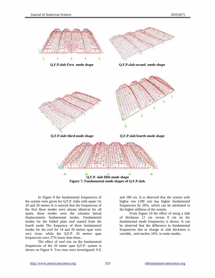
Investigated systems were subjected to free vibrations analysis. Eigen values and Eigen vectors are adopted in the linear dynamic analysis. It was noticed - for the investigated spans, with different parameters - that the arrangement of mode shapes was consistent. Columns lateral displacements dominated the first three modes, and then roof deformations controlled the next
ones. Figure .7. displays the roof modes, it can be seen that the dominating mode for the Q.F.P. slab is the intermediate symmetric bending mode The second mode was antisymmetric bending, followed by symmetric bending of the external spans. Alternative modes of antisymmetric, and symmetric plate bending follows.
Journal of American Science 2010;6(7)
http://www.americanscience.org [email protected] 323
Q.F.P.slab First mode shape Q.F.P.slab second mode shape
Q.F.P.slab third mode shape Q.F.P.slab fourth mode shape
Q.F.P. slab fifth mode shape
Figure 7: Fundamental mode shapes of Q.F.P.slab.
In Figure 8 the fundamental frequencies of the system were given for Q.F.P. slabs with spans 14, 20 and 26 meters It is noticed that the frequencies of the first three modes were almost identical for all spans, these modes were the columns lateral displacements fundamental modes. Fundamental modes for the folded plate roof started from the fourth mode The frequency of three fundamental modes for the roof for 14 and 20 meters span were very close, while the Q.F.P. 26 meters span frequencies were 27% lower than them..
The effect of roof rise on the fundamental frequencies of the 20 meter span Q.F.P. system is shown on Figure 9. Two rises were investigated: 0.9,
and 180 cm. It is observed that the system with higher rise (180 cm) has higher fundamental frequencies by 20%, which can be attributed to the higher stiffness of the system.
From Figure 10 the effect of using a slab of thickness 12 cm versus 8 cm on the fundamental mode frequencies is shown. It can be observed that the difference in fundamental frequencies due to change in slab thickness is variable, and reaches 16%. in some modes.

Journal of American Science 2010;6(7)
http://www.americanscience.org [email protected] 324
Fig. 8: Fundamental modes frequencies for folded
plate roofs with different spans.
Fig. 9: Effect of folded plate rise on fundamental
frequencies of 20 m span system.
Fig.10: Fundamental modes of 20 meters span
Q.F.P with different slab thicknesses.
3. Discussion of Results For the longest Q.F.P system in the study (26
m span), increasing diaphragm stiffness by 15 times the original stiffness reduces Q.F.P. static deflections by 54%, while doubling the slab rise from 90 cm to 180 cm reduced this deflection by 64%.
Increasing end diaphragm stiffness had higher effect on static deflection control, than slab stresses, as increasing its stiffness by 10 times (increasing width from 10 to 100 cm) - in the longest system -reduced deflection by 38.5%, and corresponding reduction in maximum stresses in Q.F.P slab was 25%.
Increasing intermediate beams stiffness up to 6 times reduced the maximum deflection by a maximum of 17% for the longest investigated 26 meters span
The increase in rise was more significant in shorter spans. Maximum deflection in 14 meters span was less by 8% than 26 m span roof.
Mode shapes patterns arrangement was not affected by variation in spans from 14 to 26 meters. In other words, mode shapes came in the same order for all investigated spans.
Slab thickness in Q.F.P. systems has a variable effect on the free vibration analysis of the slabs. A difference reaching 16% in fundamental frequencies of the system was noticed on changing the slab thickness from 8 to 12 cm.
Doubling the roof rise (from 0.9 to 1.8 meters) increased the fundamental frequency of the Q.F.P. slab by 20%.
Spans between 14 to 20 meters had very close slabs fundamental frequencies. On the other hand difference widens significantly on reaching 26 meters spans. 4. Conclusion
Approximate static solutions that propose fixed boundary conditions at the end diaphragms for the Q.F.P slab ends [9,10,11] are not reliable for longer spans – especially for spans 20 meters or more. Thus, numerical modeling that takes into consideration their stiffness is recommended.
Previous literature neglected slab thickness in proposed analytical dynamic linear free vibrations solutions [14]. This study highlighted the possible loss in accuracy that reached 16% in some of the modes –of the investigated Q.F.P system- when the slab thickness varied from 12 to 8 cms.
Increasing folded plate rise was the most efficient factor among the investigated

Journal of American Science 2010;6(7)
http://www.americanscience.org [email protected] 325
parameters in the static analysis for deflection control.
On the other hand increasing the roof rise lead to an increase in the fundamental frequencies of the system.
Rise effect was most effective in shorter spans. Increasing folded plate rise enhanced the structural behavior of the overall Q.F.P. system than increasing intermediate beams stiffness.
Increasing stiffness of intermediate beams has limited effect on roofs with higher rises, and shorter spans.
Increasing folded plate thickness has limited effect on the change in static deflections, or straining actions of the system.
The static behavior of the system was slightly sensitive to increase in end diaphragm stiffness, especially in shorter spans.
Spans from 14 to 20 meters for the investigated Q.F.P. slabs had very close fundamental frequencies, this effect widens noticeably on analyzing longer spans. Corresponding author 1H. Elkady 1Civil Engineering Dept., National Research Center,
Cairo, Egypt 5. References 1. Cheung YK.,”Folded plate structures by finite
strip method.”, Jr of Struct Div ASCE 1969;95:2963–79.
2. Golley BW, Grice WA.,”Prismatic folded plate analysis using finite strip-element.”, Comput Methods Appl Mech Eng 1989;76:101–18.
3. Eterovic AL, Godoy LA.,” An exact-strip method for folded plate structures.”, Comput Struct 1989;32(2):263–76.
4. Ohga M, Shigematsu T, Kohigashi S., “Analysis of folded plate structures by a combined boundary element-transfer matrix method”, Jr. of Comput Struct 1991;41(4):739–44.
5. Liu WH, Huang CC.,” Vibration analysis of folded plates.”, Jr. of Sound Vibr 1992;157(1):123–37.
6. Perry B, Bar-Yoseph P, Rosenhouse G., “ Rectangular hybrid shell element for analyzing folded plate structures.”, Comput Struct 1992;44(1–2):177–85.
7. Duan M, Miyamoto Y. , “Effective hybrid/mixed finite elements for folded-plate structures.”, J Eng Mech 2002;128(2):202–8.
8. Guha Niyogi A, Laha MK, Sinha PK., Finite element vibration analysis of laminated composite folded plate structures”, . Jr. of Shock
Vibr 1999;6:273–83. 9. Bar-Yoseph P, Hersckovitz I., “Analysis of
folded plate structures.”, Jr. of Thin-Walled Struct 1989;7:139–58.
10. Bandyopadhyay JN, Laad PK.,”Comparative analysis of folded plate structures.”, Jr. of Comput Struct 1990;36(2):291–6.
11. Peng L.X, Kitipornchai S., Liew K.M. ,”Bending analysis of folded plates by the FSDT meshless method”, Journal of thin walled str. 44, 2006, p 1138-1160.
12. Belytschko T, Lu YY, Gu L. ,”Element-free Galerkin methods”, . Int J Numer Methods Eng 1994;37:229–56.
13. Liew KM, Ng TY, Wu YC.,” Meshfree method for large deformation analysis—a reproducing kernel particle approach.”, Eng Struct 2002;24(5):543–51.
14. Bernadou .M, “Finite Element Methods for Thin Shell Problems”, J. Wiley & Sons, 1996.
15. Chapelle B, K.J. Bathe, “ Fundamental considerations for the finite element analysis of shell structures”, Comput. Struc. 66 (1998) 19–36.
16. Liew KM, Wu YC, Zou GP, Ng TY., “Elasto-plasticity revisited: Numerical analysis via reproducing kernel particle method and parametric quadratic programming”, Int J Numer Methods Eng 2002;55(6):669–83.
17. Liew KM, Huang YQ, Reddy JN. “Moving least square differential quadrature method and its application to the analysis of shear deformable plates.”, Int J Numer Methods Eng 2003;56(15):2331–51.
18. Liew KM, Zou GP, Rajendran S., “ A spline strip kernel particle method and its application to two-dimensional elasticity problems.”, Int J Numer Methods Eng 2003;57(5):599–616.
19. Liew KM, Chen XL., “ Buckling of rectangular Mindlin plates subjected to partial in-plane edge loads using the radial point interpolation method”, . Int J Solids Struct 2004;41(5–6):1677–95.
20. Liew KM, Cheng Y, Kitipornchai S., “ Boundary element-free method (BEFM) for two-dimensional elastodynamic analysis using Laplace transform.”, Int J Numer Methods Eng 2005;64(12):1610–27.
21. Liew KM, Ren J, Reddy JN., “Numerical simulation of the thermomechanical behaviour of shape memory alloys.”, Int J Numer Methods Eng 2005;63(7):1014–40.
22. Liew KM, Cheng Y, Kitipornchai S.,

Journal of American Science 2010;6(7)
http://www.americanscience.org [email protected] 326
“Boundary element-free method (BEFM) and its application to two-dimensional elasticity problems.”, Int J Numer Methods Eng 2006;65(8):1310–32.
23. Chen JS, Pan C, Wu CT, Liu WK., “Reproducing kernel particle methods for large deformation analysis of nonlinear structures.”, Comput Methods Appl Mech Eng 1996;139:195–227.
24. Liew KM, Wang J, Tan MJ, Rajendran S. , “Postbuckling analysis of laminated composite plates using the mesh-free KP–Ritz method “, . Comput Methods Appl Mech Eng 2006;195(7–8):551–70.
25. Ren J, Liew KM. , “Mesh-free method revisited: two new approaches for the treatment of essential boundary conditions. “, Int J Comput Eng Sci 2002;3(2):219–33.
26. Wang J, Liew KM, Tan MJ, Rajendran S., “ Analysis of rectangular laminated composite plates via FSDT meshless method.”, Int J Mech Sci 2002;44:1275–93.
27. Liew KM, Lim HK, Tan MJ, He XQ. , “Analysis of laminated composite beams and plates with piezoelectric patches using the element-free Galerkin method.”, Comput Mech 2002;29(6):486–97.
6/2/2010