effect of fiber inclination on crack bridging stress in brittle fiber ...
30
0022 5096:92 %S.OO+O.OO 'T; 1992 Pqamon Press Ltd EFFECT OF FIBER INCLINATION ON CRACK BRIDGING STRESS IN BRITTLE FIBER REINFORCED BRTTTLE MATRIX COMPOSITES CHRISTOPHER K. Y. LEUNG Department of Civil Engineering, Massachusetts Institute of Technology. Cambridge, MA 02139, U.S.A. and VICTOR C. Lr Advanced Civil Engineering Materials Research Laboratory. Department of Civil Engineering, University of Michigan. Ann Arbor, MI. U.S.A. ABSTRACT THE MECHANICAL behavior of brittle matrix composites is strongly affected by the bridging of cracks by fibers. In random fiber composites, libers can lie at an angle to the crack plane. Under such conditions, the bridging stress for a certain crack opening is governed by various micromcchanisms including fiber debonding, fiber bending and rupture as well as matrix spailing. While fiber debonding has been widely investigated, the coupled fiber bending~m~trix spaliing mcch~nism has received little attention. In this paper, the fiber bending/matrix spilling mechanism is analyzed by treating the fiber as a beam bent on an elastic foundation with variable stiffness and the possibility of spalling. The foundation stiffness and spalling criterion are derived from a tinite element analysis. The bridging stress due to bending alone as well as the total bridging stress are then obtained for the case with brittle fibers. Through this analysis. the effect of various microstructural parameters (such as fiber and matrix moduli, matrix spalling strain and fiber/matrix interfacial friction) on the behavior of random fiber composites cztn be studied. Prediction of ln~fx~rnurn bridging stress for inclined fibers based on the present model is shown to be in good agreement with experimental results. I. INTROD~JCTION BRITTLE MATERIALS usually fail by the unstable propagation of cracks. When fibers are incorporated into a brittle matrix, provided the fiber/matrix interfacial bond is weak enough (COOK and GORDON, 1964; EVANS et ai., 19X9), the fibers can debond from the matrix and then act as bridging ligaments at the crack wake to reduce the stress intensity factor at the tip of the crack. As a result, the first cracking strength of the material (i.e. the applied stress at which unstable propagation of the largest inherent crack occurs) is increased (AV~STON eb al., 1971 ; HANNANT et al., 1983: MARSHALL er al., 1985; LI and LEUNG, 1991). Moreover, with bridging stress at the crack wake, there is a lower sensitivity of first-cracking strength to the variation of inherent flaw size (MARSHALL et al., 1985 ; KENDALL et nl., 1987; LEUNG and Lr, 1989; LI and LEUNG, 1991). Reliability of the material is therefore improved. After 1333
Transcript of effect of fiber inclination on crack bridging stress in brittle fiber ...

0022 5096:92 %S.OO+O.OO 'T; 1992 Pqamon Press Ltd
EFFECT OF FIBER INCLINATION ON CRACK BRIDGING STRESS IN BRITTLE FIBER REINFORCED
BRTTTLE MATRIX COMPOSITES
CHRISTOPHER K. Y. LEUNG
Department of Civil Engineering, Massachusetts Institute of Technology. Cambridge, MA 02139, U.S.A.
and
VICTOR C. Lr
Advanced Civil Engineering Materials Research Laboratory. Department of Civil Engineering, University of Michigan. Ann Arbor, MI. U.S.A.
ABSTRACT
THE MECHANICAL behavior of brittle matrix composites is strongly affected by the bridging of cracks by fibers. In random fiber composites, libers can lie at an angle to the crack plane. Under such conditions, the bridging stress for a certain crack opening is governed by various micromcchanisms including fiber debonding, fiber bending and rupture as well as matrix spailing. While fiber debonding has been widely investigated, the coupled fiber bending~m~trix spaliing mcch~nism has received little attention. In this paper, the fiber bending/matrix spilling mechanism is analyzed by treating the fiber as a beam bent on an elastic foundation with variable stiffness and the possibility of spalling. The foundation stiffness and spalling criterion are derived from a tinite element analysis. The bridging stress due to bending alone as well as the total bridging stress are then obtained for the case with brittle fibers. Through this analysis. the effect of various microstructural parameters (such as fiber and matrix moduli, matrix spalling strain and fiber/matrix interfacial friction) on the behavior of random fiber composites cztn be studied. Prediction of ln~fx~rnurn bridging stress for inclined fibers based on the present model is shown to be in good agreement with experimental results.
I. INTROD~JCTION
BRITTLE MATERIALS usually fail by the unstable propagation of cracks. When fibers are incorporated into a brittle matrix, provided the fiber/matrix interfacial bond is weak enough (COOK and GORDON, 1964; EVANS et ai., 19X9), the fibers can debond from the matrix and then act as bridging ligaments at the crack wake to reduce the stress intensity factor at the tip of the crack. As a result, the first cracking strength of the material (i.e. the applied stress at which unstable propagation of the largest inherent crack occurs) is increased (AV~STON eb al., 1971 ; HANNANT et al., 1983:
MARSHALL er al., 1985; LI and LEUNG, 1991). Moreover, with bridging stress at the crack wake, there is a lower sensitivity of first-cracking strength to the variation of inherent flaw size (MARSHALL et al., 1985 ; KENDALL et nl., 1987; LEUNG and Lr,
1989; LI and LEUNG, 1991). Reliability of the material is therefore improved. After
1333

1334 c’. K. Y. LHJNG and V. C. LI
the formation of the first through crack, if the fibers can take further load by themselves, pseudo-dLlctile behavior with multiple cracking will be obtained. This pseudo-ductility provides warning to the material user before the occurrence of final failure and allows redistribution of stresses to less severely loaded parts of the struc- ture.
The improvements in material performance with the incorporation of fibers can bc derived qua~tit~tti~~ely by analyzing the propagation of a bridged crack provided the bridging stress for a given crack opening (or the p II relation) is known ( M.ARSHAI.I.
ef cd.. 1985; L.EIJXi and LI, 1989). When fibers are lying perpendicular to the crack plane, as in aligned fiber composites loaded in the fiber direction, crack bridging stress arises from the stretching of debonded fibers. For such a case, the p-lr relation has been derived through the analysis of fiber debonding for both continuous fiber (MARSHALL et cd.. 1985) and discontinuous fiber composites (LEUNG and Lr, 1990). When fibers are not perpendicular to the crack plane. as in randotn fiber composites, the opening of a crack will lead to fiber bending and shear in addition to fiber debonding (Fig. la). The crack bridging force (from a single fiber) is then made LIP
of two components. one from the fiber/matrix interfacial stress and the other from reactions due to bending of fiber against the matrix (Fig. lb). Assuming that these two ~ornpo~lellts can be decoupled, the bridging force can be obtained as their vector suili. (Note, thecompositecrack bridging stresscan then be obtained frotn the product of the bridging force per fiber and the number of fibers per unit crack area.) The component due to interfacial shear stresses can be derived from existing fiber debond- ing theories as in the aligned fiber case. In this paper, a model for the derivation of
V Fib& Subjected to Bending end Shear
FIG. 1. (a) Bending and shearing of’liber across a cr:xk. (h) Components of a crack bridging force

Crack bridging by inclined fibers 1335
bridging stress due to fiber bending will be developed for composites with brittle fiber
and brittle matrix. For a brittle fiber reinforced brittle matrix composite. while bending and shearing
may lead to fiber breakage, force acting on the matrix from the fiber may also lead to matrix spalling at the exit point (Fig. 1 b). Matrix spalling under inclined fibers have been observed in several matrix materials such as polyester resin (MORTON and GROVES, 1974) and mortar (Lr et al., 1990). Since the spalling of matrix can lead to relaxation of the fiber as well as the delaying or prevention of fiber breakage, it has a strong effect on the bridging stress arising from fiber bending. As a result, a coupled analysis of the fiber bending/matrix spalling mechanism is crucial in the derivation of crack bridging stress.
In the following, previous work on the modelling of bridging effects of inclined fibers are reviewed and a new model, which effectively considers the fiber as a beam and the matrix as an elastic foundation, is introduced. Determination of stiffness and spalling criterion for the matrix foundation is then described. The bridging stress due to fiber bending is numerically obtained. Results are discussed in terms of the various microscopic parameters affecting the bridging mechanism. Then, the total crack bridging stress (due to both fiber bending and debonding) is obtained for several combinations of micro-parameters. Implications of the results to the choice of micro- parameters in the design of random fiber composites are discussed. Finally, theoretical prediction of maximum bridging stress from inclined fibers is compared with exper- imental results on a glass fiber reinforced polyester system to assess the validity of the present model.
2. CHOICE OF AN APPROPRIATE MODEL
2. I. Reciebrt of existing models
Crack bridging by oblique fibers have been studied by several investigators for various material systems. PIGGOTT (1974) considered the bending of brittle fibers in a rigid perfectly plastic matrix. In the model, the fiber is considered to be a flexible string with no bending stiffness. The fiber/matrix interfacial stress is assumed to have a magnitude equal to r,., the yield strength of the matrix, and act at an angle n(d - $) to the fiber axis. 4 is the original angle a fiber element makes with the horizontal axis, $ is the angle it makes after deformation (Fig. 2) and n is a constant to be determined
(a) (b)
PK. 2. Assumptions of Piggott’s model : (a) a tiber bent on the matrix, (b) enlarged view of part of a tiber showing stress on a fiber.

1336 c. K. Y. LEUNG and V. C. LI
empirically from experimental data. With these assumptions, the maximum curvature of the fiber can be obtained. From the maximl~In curvature, the nlaximum stress caused by bending and hence the strength reduction of the fiber due to bending are deduced. As a result of its assumptions, this model is only valid for cases with flexible fibers and matrix with very low yield stress and yield strain. Surprisingly, the model has been used successfully to fit experimental data of 0.76 mm glass fiber bundles (which are quite stiff) embedded in brittle polyester resin. It appears that the fitting parameter I? is able to provide some flexibility to the model so data that violate the basic assumptions may also be fitted. However, since IZ is an empirical constant, the dependence of composite behavior on micro-properties is not reflected in the value of II and so fitting data with n does not provide much insight to composite design.
MORTON and GROVES (1974) analyzed the bridging effects of inclined ductile fibers in a yielding matrix by considering the bending of fiber across a crack. In the analysis, interfacial shear stress is neglected and the reaction stress from the matrix on the fiber is taken to be the matrix yield strength. With these simplifying assumptions, the bridging stresses for a certain crack opening and fiber inclination angle are derived for two different cases: the case with the fiber remaining elastic and the case with plastic hinges formed in the fiber. However, since the transition between these two cases (when the fiber is in an el~~sto-plastic stage) has not been considered, the rn~~xirn~lrn bridging stress for a certain fiber inclination angle can only be deduced approximately. The model tends to be in better agreement with experimental results at low fiber inclination angles. At higher angles. the discrepancy is attributed to extensive matrix yielding or matrix spalling that tends to relax the fiber.
LI ct ~2. (1990) considered the case with flexible fibers bending on an elastic matrix. In this model, the fiber is so flexible that the reaction forces can be considered to be concentrated on a very small area at the exit point of the matrix rather than spreading over a large area as in Fig. I. The exit point can then be modelled as a pulley over which the fiber passes. The high local noi,mal stress at the exit point induces high local friction. By modeling the fiber as a string passing over a frictional pulley, Li et cd. obtamed a good prediction for the bridging stresses of inclined synthetic fibers in a mortar matrix. This model. which assumes large deforrn~lti~~n of the fiber into a curved string, is only valid if the fiber possesses a high rupture strain.
Of the three models described above, Piggott’s and Morton and Groves’ models are based on the assumption of a yielding matrix, which renders them inapplicable
to brittle matrix composites. On the other hand, Li cf crl’s model, which assumes a “string-like” fiber with high rupture strain. is not applicable to brittle hbcrs. For brittle fiber reinforced brittle matrix composites. a new model has to be developed.
From the above discussion, a brittle fiber can be best represented by an elastic beam. Since the brittle matrix will remain elastic until the occurrence of spalling, it can be modelled as an elastic foundation supporting the fiber. The bridging stress due to bending of a single fiber can then be derived by analyzing the bending of fiber on an elastic foundation provided the foundation stiffness and foundation spalling criterion (in terms of the applied force per unit length when spalling occurs) arc

Crack bridging by inclined fibers 1337
\ Q
Applied Displacement
SECTION A-A
- Middle Line Constrained to Move Together
FIG. 3. Plane strain model for the determination of foundation stiffness and foundation spalling criteria.
known. Since the volume of matrix below the fiber varies with distance from the crack face (Fig. 3), the foundation properties are variable along the fiber. To obtain the properties of the foundation, we consider a section of the composite cut in a direction perpendicular to the fiber (Fig. 3). The section is assumed to be under plane strain. In Fig. 3, h, the distance from the bottom of the fiber to the crack face, is a function of the distance x along the fiber. The fiber and matrix are assumed to be unbonded to each other but under smooth or fictional contact. This is a reasonable assumption because the matrix reaction on the bent fiber drops rapidly with distance from the crack face and in the region close to the crack face where there is significant reaction stress, the fiber is very likely to have debonded from the matrix for most practical composite systems. In this model, only one fiber is considered, thus neglecting fiber interaction effects. Load is applied to the middle line of the fiber, which is constrained to move vertically with the same displacement along the whole line (Fig. 3). From the displacement of the middle line (u,) and the stress field produced by a certain applied force F, the foundation stiffness and spalling criteria can be obtained. It should be noted that when the fiber on an elastic matrix is bent at one end, it deforms in an oscillatory shape. In other words, the fiber can touch both the top and bottom of its groove. Therefore, foundation stiffness values have to be obtained for both cases with fiber pressing on the bottom or the top of its groove. Spalling, on the other hand, always occurs at the matrix at the exit point around the bottom half of the fiber and

1338 C. K. Y. LELW and V. C. LI
so the spalling criteria need only be derived for the case with the fiber pressing on the bottom of its groove.
In summary, to obtain the bridging stress due to fiber bending, the 3-D problem of a fiber bent in its matrix groove is simplified into two 2-D problems: a plane strain problem for the determination of the effective stiffness and spalling criterion of the matrix foundation and the problem of a beam bending on an elastic foundation with variable stiffness as well as the possibility of spalling. Since closed form analytical results for these problems are not available, numerical techniques involving finite elements arc employed. A solution of the problems and important implications of the results will be discussed in the following sections.
3. DETERMINATION OF FOUNIIATIOX STIFFIGESS AND SPAI,T,ING CRITERION
3. I. Detcrrninutiorl of’H, urzd HZ
The geometry of the plane strain problem for the determination of foundation properties is illustrated in Fig. 3. In the model, H, and H2 are distances from the fiber to the outer boundary of the specimen and can be taken as infinite compared to the fiber size. However, in a finite element model, finite values of H, and H2 have to be employed. Since a stiffness value is to be obtained, the choice of H, is very critical because the displacement for a certain applied load increases with increasing H, (thus resulting in decreasing stiffness). To obtain a reasonable estimate of H,, it is realized that we have actually replaced a problem of stresses acting over a finite area (equal to the projected area of fiber on the matrix) over a semi-infinite medium (Fig. 4a) with one with an infinite strip of stress (Fig. 4b). A logical choice of H, is thus a value such that the relative displacement to the middle line of the infinite strip and a line at a distance H, below is equal to the displacement at the middle of the corresponding finite loaded area (see Fig. 4). To find the displacement below the finite loaded area.
I-$ chosen so that displacement under line p-p and 0 are the same
for the same applied load/area
FIG. 4. Criteria for sleeting H, for the linite element mesh.

Crack bridging by inclined fibers I339
the length and width of the strip have to be known. The width is simply the diameter of the fiber while the length is arbitrarily chosen to be the length beyond which the foundation reaction stress is less than l/200 times the reaction stress at the exit point. After going through the mathematical details given in the Appendix, HI is deduced to be 34 times the radius of the fiber.
The choice of N2 should ensure that the stress fieid outside Hz does not have significant effect on the displacement below the fiber. We arbitrarily take H, to be equal to H, and then compute the displacement and maximum stress (numerically, with finite element models to be described below) under the same applied load for two cases : one with rollers along the top boundary and free side boundaries and the other with top and side boundaries fixed. The real situation should be in between these two cases. The displacements at the middle of the fiber for the two cases are found to be within 3.5% of each other while the maximum stress in the matrix is found to be within 0.5% difference between the two extreme cases. The use of either boundary conditions is thus expected to give reasonable results. In all subsequent calculations, the more flexible boundaries (with rollers and free sides) are used.
For the purpose of determining the matrix spalling criteria, we are interested in the stress field around the fiber. The finite element model therefore has to be very refined around the regions with expected high stresses. For small h (Fig. 5a), high tensile
(a) Small h
Large h
Maxim;m Principal Tensile stress
0 0 0 0 0 0 0 o_
Maximum Principal Tensile Stress
FIG 5. Location of maximum principal tensile stress for both small and large h.

1340 C. K. Y. LFUYG and V. C. LI
stresses are expected to occur at the bottom of the matrix ligament below the fiber due to bending, while, for large h, maximum stress is expected to be around the edge of the contact region between the fiber and matrix (Fig. 5b). (Note, this conjecture is indeed proven to be true by subsequent finite element results.) Mesh refinements are carried out in these regions until the stress values at a nodal point deduced by extrapolation from Gaussian points in the two adjacent elements are within 5% in most cases. Examples of final meshes are shown in Fig. 6. Due to symmetry, only half of the plate need be modelled. Double noding is carried out at the boundary of fiber and matrix so they are not connected to each other. In Fig. 6b, the thick black circular arc shows the region where contact between fiber and matrix is allowed. Shown in the figure are cases where the fiber is pressing on the bottom of its groove. To compute stiffness for the case when the fiber is pressing on the top of the groove. the contact region is prescribed on the upper half of the fiber circumference instead.
Solution to this fiber/matrix contact problem is obtained with the ADINA finite element analysis program. Full Newton iteration is employed in the solution scheme. Results converge for all cases when smooth contact is assumed between fiber and matrix (i.e. frictional coefficient ,H = 0). For Coulomb friction models. results fail to converge when /I is small and I?, is high. Due to the use of highly refined meshes, the solution to the problem involves a lot of number crunching and hence requires significant computation power. The MIT Cray-2 supercomputer was used in carrying
(b)
See Fig.6c
See Fig.6d
‘\
1.1~~. 6. A typical finite clement mesh: (a) the whole mesh, (b) details around fiber

Crack bridging hy inclined lihcrs 1341
(d)
FIG. 6. (c). (d) Refinements at regions of high stress
out all the computations. Depending on the mesh size and other parameters such as frictional coefficient and moduli ratio, a typical run takes about 100~200 cpu seconds on the Cray-2.
3.3. Linearity of the problem
In general, the contact problem is a non-linear problem because the area of contact may change significantly with applied load. However, for the particular problem we are looking at, where the fiber is in contact with the lower part of a matrix groove with the same radius. there may not be much change in contact area with load and the displacement and maximum stress of the matrix foundation (more details in the following section) can be taken as linearly increasing with load. To confirm the validity of this argument, test cases are run with the same /I, same fiber and matrix parameters but with changing applied load. Results are shown in Fig. 7. It is observed that, for several combinations of fiber and matrix properties, both the fiber displacement (i.e. displacement at the fiber middle line, where load is applied) and the matrix maximum strain vary linearly with applied load. The range of load is selected so that the maximum matrix strain ranges from around 0.004%--0.2%. With linearity ascertained in this wide range of matrix strain, one can treat the matrix foundation as linear springs, which save a lot of subsequent computations.

I342 (‘. K. Y. Lt.UNG and V
-c E, = 0.25 E,
- E, = 0.25 E,
Y, = 0.35
“,= 0.20
APPLIED LOAD
$ 0 PO 40 60 80 100
APPLIED LOAD
FIG;. 7. Linearity of the contacl problem. (Note. units in upper figure arc arbitrarily chosen.)
3.4. Deril~cd,fhl*,ltl~iion poprrrirs
In the plane strain finite element model, a total load F per unit length is applied to the mid-line of the fiber cross-section. From the analysis, the vertical displacement of the mid-line (with all points on it constrained to move together). u,, and the maximum principal tensile stress produced by the loading, gn,,,x, can be obtained. The foundation
stiffness defined as the force per unit length per unit vertical displacement is then given by h-,,, = F/u, or. in non-dimensional form, k,,,jE,,, = F/(u,E,,,), where E,,, is the matrix modulus. The spalling criterion can be expressed in terms of the applied force per unit length, F,,,. when spalling occurs, or. in non-dimensionalized form, F,,,/(ro,,,), where I is the fiber radius and n,,, is the matrix strength (= E,,J:,,,, with I:,,, being the matrix failure strain). Thus, spalling is assumed to occur when the matrix material in the vicinity of the fiber reaches the failure strain c,,,. For this problem, as a result of the linear variation of matrix stress (or strain) with applied force (Fig. 7), F,,,/(ro,,,) can be obtained directly as F/(Y(T,,,:,~) for any applied force.
(k,l,/E,,I)B and (li,,/E,,,)T. with subscripts Band Tto indicate cases when fiber contacts with the bottom or top of the matrix groove respectively, as well as the spalling criterion F,,,((ro,,,) are functions of /I/Y (the normalized depth of matrix below the fiber), E,/E,,, (ratio of the fiber and matrix modulus), 11,. viri (Poisson’s ratio of fiber and matrix) and p, the frictional coefficient between fiber and matrix. In this paper, we will focus on the variation of foundation properties with /z/l and E,/E,,,. keeping the other parameters fixed at 11, = 0.25, 11,~~ = 0.25 and ,D = 0.25. The effects of varying
v,, \I,,~ and p on foundation properties have been investigated and reported in LEUNG (1990). For the same h/r and E,/E ,,,, as v,. v,,~ and ,U are varied within reasonable
limits, the values of foundation properties always lie within 10% of the values at \I, = 0.25, v,,, = 0.25 and p = 0.25.

Crack bridging by inclined fibers I343
The variation in foundation stiffness and spalling criteria with h/v and E,/E,,, is
shown in Fig. 8 for E,/E,,, equal to 0.25, 1.0 and 6.0. While (k,,jEm)B and (~,~,/~,,,)~ vary a lot with E,/E ,,,, FJro,,, is relatively insensitive to E,/E ,,,. Values are cal- culated for h/r up to 33, when the distance of fiber center to the crack face (i.e. h+r)
is equal to H,. For h/r > 33, values for foundation stiffness and spalling criteria are assumed to be the same as for h/r = 33. Since (k,,l/E,,I)r does not vary a lot with h/r,
its value is only obtained at 3 points (h/r = 1, IO, 33). For h/r < 1, (~,,*~~,~~)~is assumed to be equal to the value at h/r = 1. For all cases, both the stiffness and spatling force
(a)
0.5
k--l km 0.4
m B I Ef=E,
0.3 - Ef = 0.25 E,,, 0.2 - Ef =6Em
_._ _ 0 10 20 30
hlr
(b)
0.6
0.4 -
km
k--I m T o.3 - l 4, I Ef = E,
- Ef = 0.25 Em 0.2 - - Ef =6Em
7
Eli 0 10 20 30
hlr
- Ef =Em
1 - Ef = 0.25 Em - Ef =6E,,,
hlr
FIG. 8. Variation of foundation properties with h/r and E, !E,,,.

1344 C. K. Y. Leum and V. C. LI
are expected to increase with increasing /Z/Y with gradually decreasing rate. This trend is shown in all data curves except the one for spalling stress with E,/E,,, = 6. The slight drop in spalling force at h/r = 22 is believed to be caused by numerical errors of the computational model. As mentioned before. there are several cases with high E, and low II/I. (< 1) in which the contact problem fails to converge when p = 0.25. In those cases, solutions are obtained for the cast with /L = 0 and corrected to the frictional case by assuming that the displacement and maximum stresses for a certain /z:‘R in the frictional and frictionless cases can be proportioned as in the cases when /I/I. = I (where convergence can always be attained).
When E,;‘E,,, becomes larger, the stiffness curves and spalling force curves are expected to approach certain limiting curves corresponding to the case where the fiber can be considered rigid relative to the matrix. To obtain the value of E,/E,,, beyond which the fiber can be taken as rigid, foundation stiffness and spalling force are plotted at several values of h;r for E, /E,,, values of I. 3. 6 and IO (Fig. 9). While the numerical results for spalling force do not show an obvious trend (probably due to higher numerical errors in these results than the stiffness results). the foundation stiffness values show little change beyond E,jE,,, = 6. Consequently, when E,iE,,, is greater than or equal to 6, the fiber can be considered to be rigid with respect to the matrix, and foundation properties equal to those at E,!‘E,,, = 6 can be used. This is a useful finding because it allows direct applications of our data to composites of polymers and other soft matrices (whcrc E,/E,,, is usually greater than 6) without requiring
another series of heavy computation.
4. DERIVATION OF BRIIXING STRESS DUE TO BENDING AI,ONE
After obtaining the foundation stiffness and spalling force. the crack bridging stress for a given crack opening can now be determined by analyzing a beam bent on a foundation with variable stiffness and the possibility of spalling. The formulation is similar to that in MOKTON and GROVES (1974) except that the matrix is considered to be brittle and elastic rather than plastic as in their case. In the analysis, the fiber is separated into two free bodies at the middle of the crack whcrc the point of inflection is located (Fig. IO). The force F, to produce a displacement (S at the fiber end (and hence to ensure connectivity of the fiber on the two sides of the inflection point) is to be computed. Note that F, is equal to the resultant of reaction forces due to bending of fiber on the matrix (R in Fig. I). The bridging force due to bending alone is then the component of F, in a direction normal to the crack plane. To obtain F, for a certain crack opening, the displacement ci and the free length of beam outside the elastic foundation, I,. have to be known. Following Morton and Groves, 6 and 1, can be exprcsscd in terms of the half crack opening. II. and the fiber radius. r, as :
ci = II sin 0. (1)
I, = I’ tan 0 + II cos f), (2)
where I) is the angle between the fiber and the normal to the crack plane. In the

Crack bridging by inclined fibers I345
km (T-l mT
::I’ 0 10 20 30
h/r
i .
: .
0.5 - .
I . .
. 0.4 ,
0 10 20 30
h/r
2.0
IA-
1.6- t :
1.4-
1.0-A .I
0.8 -I 0 10 20 30
hlr
b E,=E,
. E,=3E,
. q=6E,
l E,=lOE,
A E,=E,
. 4=3E,
. E,=6E,
. E,=lOE,
A E,=E,
. E+=3E,
. E,=6E,
. E,=lOE,
FE. 9. Foundation properties approaching the rigid fiber case for increasing E, !/I?,,,.
expression for I,, the first term is contributed by the part of fiber separated from the matrix on bending (Fig. 10) and the second term is due to displacement of fiber into the crack.
For the case of beam bending on non-spalling elastic foundation with uniform stiffness. once 6 and I, are specified, F, can be readily obtained from analytical solutions (TIMOSHENKO, 1976). With non-uniform stiffness and spalling, a closed form solution is not available and a numerical analysis employing finite elements is carried out. The fiber is represented by beam elements. The beam stiffness matrix is derived

1345 C. K. Y. LLXJNC; and V. C. LI
Fiber Divided into Two Free Bodies
I:IG. IO. Configuration for the determination of bridging stress due to bending
by an approach suggested by SEVERN (1970), which takes into consideration shear deformation of the beam. To model the matrix, the volume of material from the mid- point of one beam element to the mid-point of an adjacent beam element is represented by a discrete spring (Fig. II). The spring properties can thus be obtained as the integral of foundation properties from one mid-point to the other. The foundation properties. derived as a function of h/r, are first transformed into a function of the distance along fiber, x (since h is also a function of s) and then quadratically interp- olated between the points with specified values. Numerical integration is then carried out to obtain the spring stiffness (for both fiber pushing up and down) as well as the spring spalling force. In the solution of the problem. two types of iterations have to be carried out. The first type of iteration determines whether a particular fiber element node is touching the upper or the lower side of its groove and hence identifies the appropriate stiffness to be used. The second type of iteration determines the number of breaking springs, which reflect the length of the spalled matrix. The iteration schemes, as well as other progratnming details are fully described in LEUNC (1990).
After deriving F,. the fiber bridging force in the direction of crack opening can be calculated from I;, sin 0. An effective fiber bridging stress, 0,. is then defined as
Continuum Foundation
Volume of Material Represented by Spring
Discrete Model
1.~. I I. Representation of the matrix foundatmn by discrete springs

Crack bridging by inclined fibers I347
F, sin B/(w’). All the subsequent results on crack bridging stress due to bending are expressed in terms of 0, normalized with material parameters.
The numerical program has been used to obtain bridging stress and matrix dis- placement for the limiting case where foundation stiffness is uniform and no matrix spalling occurs. Comparison with close form solutions shows excellent agreement.
4.2. RemIts and discussion
Results of the analysis for variable foundation stiffness are shown in Figs 12-17. In the figures, the normalized crack bridging stress due to fiber bending, the maximum
•I More steps -c Fewer Steps
Half-crack Openlng Fiber Radius
1.5
g
c 1.0
i!
i7i
&) 0.5 a ii
0.0 0.0 0.1 0.2 0.3 0.4 0.5
Half-crack Opening Fiber Radius
FIG.
--- I I I I ,
0.0 0.1 0.2 0.3 0.4 0.5
Half-crack Opening Fiber Radius
12. Effects of the step number on the solution of the fiber bending problem (0 = CT,,,/&, = 0.005).
30’. I?,/&, = I.

134X C. K. Y. Lr,t.m and V. <‘. LI
- Mare Elements 1 _ Less Elements
0 0.0 01 02 0.3 04 0.5
Half-crack Opening Fiber Radius
OOT . , * , * , , . I 00 0.1 0.2 0.3 04 05
Half-crack Opening Fiber Radius
57 I
0.0 01 02 03 04 05
Half-crack Opening Fiber Radius
FIG. 13. ERects of element numhcr on the solution d the tihcr bending problem, (0 = 30 , 6, fE,,,, = I. c,,,:E,,, = 0.005).
fiber strain as well as the spalled length (normalized by fiber radius) are plotted against half-crack opening (again normalized by fiber radius). To obtain the normalized crack bridging stress, the effective fiber bridging stress, (r!, is normalized with the parameter
O.OOl~~(~,~~,~~), where k,bf is the value of foul~dation stiffness k,?, (for beam pushing down) at A/r = 33. In all the results, a fiber embedded length of20-fiber radius is used. For the range of Et/E,,, we considered this is for all purposes equivalent to a semi- infinite fiber.
Since matrix spalling is described by a discrete increase in I, in this model, the result

Crack bridging by inclined fibers I349
:$ 1.0 Nr: za _ :p
o& m = 0.005
- = z”B 0.5
o,,fE m 0.001
Half-crack Openlng Fiber Radius
12
g 1.0
c 0.6
5 z 0.6
ki 0.4
0.2
01 0.2 03 0.4
Half-crack Opening Fiber Radius
Half-crack Opening Flber Radius
FIG. 14. Effects of matrix failure strain on crack bridging by inclined fibers (0 = 30 , E, IE,,, = I)
is expected to be dependent on the number of beam elements used to represent the fiber as well as the number of steps in getting to a certain crack opening. Figure 12 shows the effect of step number on the results when the element number is the same. With more steps, the onset of spalling can be more accurately predicted. If a small number of steps is used (i.e. a large jump from one step to another), spalling may have started between the steps, but is not detected until the next step is reached. With more steps, spalling is always predicted to occur earlier. However, the fluctuation in bridging stress and fiber strain, which depends on the length of fiber relaxed on spalling, is of similar magnitude in both cases. When the number of elements increase

1350 C. K. Y. LFI'NG and V. C LI
oi I , . , , . I 0.0 0.1 0.2 0.3 0.4 0.5
Half-crack Opening Fiber Radius
0.0 0.1 0.2 0.3 04 0.5
Half-crack Opening Fiber Radius
10, I
0.0 0.1 0.2 0.3 0.4 0.5
Half-crack Opening Fiber Radius
FIG. 15. Eff~~s of modular ratio on crack bridging by inclined fibers (0 = 30 . cr,,,/E,,, = 0.005)
(Fig. 13), the situation is different. With the same step number, there is much less fluctuation in the stress and strain results. Theoretically, if a very large number of elements are used with a very large number of steps, smooth curves will be obtained. However, in reality, if materials spall, they spall in discrete pieces of finite size. Therefore, smooth curves resulting from spalling of infinitesimal pieces may be just an artifact of the model employed. Ideally, the beam element size used for each material system should be determined from experimental observations of the spalling mechanism (e.g. in the scanning electron microscope) from which the size of the

Crack bridging by inclined fibers 1351
0.1 0.2 0.3 0.4 0.5
Half-crack Openlng Fiber Radius
0.1 0.2 0.3 0.4
Half-crack Opening Fiber Radius
0 0.0 0.1 0.2 0.3 0.4 0.5
Half-crack Opening Flber Radius
FIG. 16. Effects of fiber inclination angle on crack bridging (0 = 1545’), EJE,,, = I, u,,,/E, = 0.005)
smallest spalled piece can be determined. This size would be an appropriate choice as the beam element size in the model.
In Fig. 14, results are plotted for two different values of matrix failure strain (cr,J&). Higher matrix failure strain implies less spalling and higher bridging stress. However, the fiber strain is also higher and so it is easier for fiber breakage to occur. The effects of E, JE,, on crack bridging by inclined fibers are shown in Fig. 15. With higher EfIE,,,,
there is more matrix spalling and hence a lower fiber strain. The normalized bridging stress is higher for a lower El/E,,. The normalizing factor, 0.001J(E,k,/~~), involves both E, and Em (since k,w is proportional to E,). If E, is kept constant, a lower E,/E,
1352 C. K. Y. LFIJNG and V. C. LI
0.1 0.2 0.3 0.4
Half-crack Opening Fiber Radius
Half-crack Opening Fiber Radius
0 0.0 0.1 0.2 0.3 0.4 0.5
Half-crack Opening Fiber Radlus
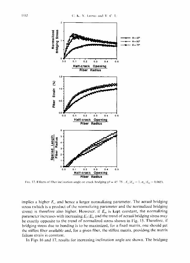
FIG. 17. ElTwts of’ fiber mcllnation angle on crack bridging (0 = 35 75 _ E, /E,,,,, = I. a,,,;E,,, = 0.005)
implies a higher E,,, and hence a larger normalizing parameter. The actual bridging stress (which is a product of the normalizing parameter and the normalized bridging stress) is therefore also higher. However, if E,,, is kept constant, the normalizing parameter increases with increasing E,/E,,, and the trend of actual bridging stress may be exactly opposite to the trend of normalized stress shown in Fig. 15. Therefore, if bridging stress due to bending is to be maximized, for a fixed matrix, one should get the stiffest fiber available and, for a given fiber, the stiffest matrix, providing the matrix failure strain is constant.
In Figs 16 and 17. results for increasing inclination angle are shown. The bridging

Crack bridging by inclinid fibers 1353
stress, fiber strain as well as spalled length all increase with inclination angle initially but decrease at higher angles. This trend can be explained by considering the expressions for 1, and 6 [(1) and (2)]. For the same half crack opening U, both the required displacement 6 and the free length of fiber 1, increase with inclination angle 0. The bridging stress (F, sin 0) increases with sin 0 and (5 but decreases with I,. Depending on the rate at which d; and 1, change with 0, the bridging stress can increase or decrease with increasing B. An interesting point to be noted is that the bridging stress curves in the range from 30” to 60’ (where most significant fiber bending is expected) do not differ significantly from each other and even the curves for 15‘ and 75 do not lie too far away. This is due to the fact that increasing bending due to a change in the angle is accompanied by an increasing force on the matrix and hence more matrix spalling. Spalling of a matrix tends to relax the more heavily stressed fibers and hence reduce the difference between fibers lying at different angles.
5. DETERMINATION OF TOTAL CRACK BRIDGING STRESS
The total crack bridging stress can be obtained by summing the individual con- tributions due to fiber debonding and bending in the direction normal to the crack plane. In this work, for illustrative purposes, results are only evaluated for the special case with continuous fibers and purely frictional fiber/matrix interface. As in the case for fiber bending, we define an effective crack bridging stress due to debonding, ctlh, to be F, cos U/d, where F2 is the bridging force in the fiber direction due to debonding alone. For a purely frictional interface, following MARSHALL et ul. (1985), the relation between the half crack opening U, effective fiber bridging stress due to debonding alone, Q<,,, and length of debonded fiber I,/, can be obtained as :
G,/,, = [4(rE,)(tl cos Q/r)(l _tq)]“’ cos fI (3)
I,,/r. = [(ucos fI/r)(E,/r)]‘~‘/(l +?/)I’? (4)
where q = ( V, E, )/( V,,,E,,,) is the relative contribution of fiber and matrix to composite modulus and u cos H is the extension of the fiber into the crack.
In the following, total bridging stresses are evaluated for various combinations of composite micro-propertles to provide insight into the choice of micro-properties for the design of random fiber composites. All the results given below are evaluated for the case with a very low volume fraction of fiber. q in the above expression can then be taken as zero. Also, the fibers can be considered to be bent in a semi-infinite volume of matrix and the results of bridging stress due to bending derived in the previous section can be applied. For composites with higher volume fractions, the bridging stress due to debonding is the same as that for a low fiber volume composite with a higher value of E, [increased by (1 + q) times, see (3) above]. Also, in the analysis of fiber bending, when there is interaction between fibers, a first approximation is to replace the matrix modulus E,,, with the composite modulus E, and then change the failure strain (for the “equivalent” matrix) accordingly. (Note, this correction is expected to be reasonable for foundation stiffness but may not be very accurate quantitatively for the spalling force.) Hence, qualitatively, one can represent random
1354 C. K. Y. LFIJNG and V. C. LI
fiber composites with high volume fraction with an equivalent composite of low fiber volume fraction. The following qualitative discussions on the effects of various micro- parameters on the behavior of a low fiber volume composite are therefore expected to be valid for composites in general.
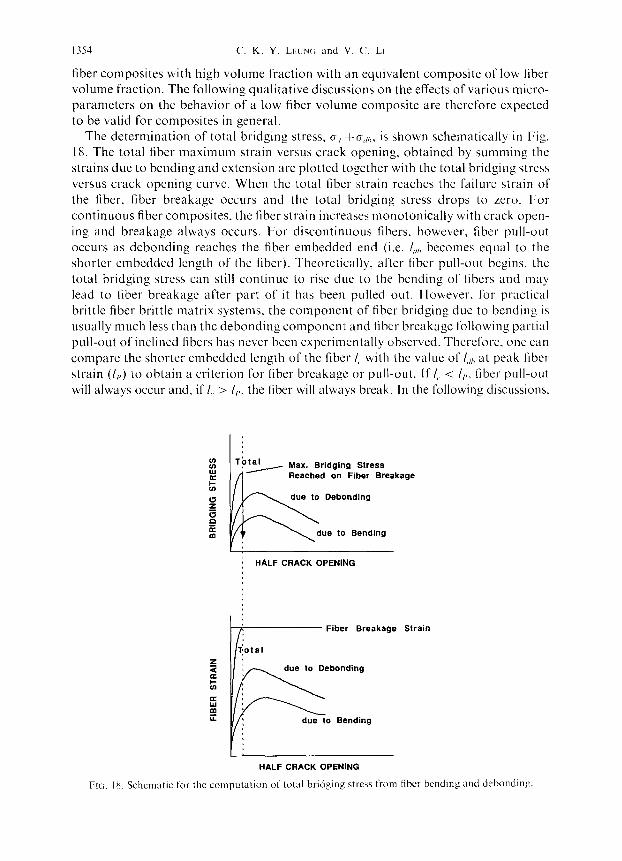
The determination of total bridging stress, C, +a,,,,, is shown schematically in Fig.
18. The total fiber maximum strain versus crack opening, obtained by summing the strains due to bending and extension are plotted together with the total bridging stress versus crack opening curve. When the total fiber strain reaches the failure strain of the fiber, fiber breakage occurs and the total bridging stress drops to Lero. For continuous fiber composites. the fiber strain increases monotonically with crack open- ing and breakage always occurs. For discontinuous fibers. however. fiber pull-out occurs as dcbonding reaches the fiber embedded end (i.e. li,,, becomes equal to the shorter embedded length of the fiber). Theoretically. after fiber pull-out begins. the total bridging stress can still continue to rise due to the bending of fibers and may lead to fiber breakage after part of it has been pulled out. However. for practical brittle fiber brittle matrix systems. the component of fiber bridging due to bending is usually much less than the debonding component and fiber breakage following partial pull-out of inclined fibers has never been experimentally observed. Therefore. one can compare the shorter embedded length of the fiber I,, with the value of I,,,, at peak fiber strain (I,,) to obtain a criterion for fiber brcakagc or pull-out. If I,. < I,,, fiber pull-out will always occur and, if I,, > I,,, the fiber will always break. In the following discussions.
Tbtal , , Max. Bridging Stress Reached on Fiber Breakage
due to Debonding
due to Bending
j HALF CRACK OPENING
Fiber Breakage Strain
due to Debonding
due to Bending
HALF CRACK OPENING

Crack bridging by inclined fibers 1355
the effect of varying one particular micro-parameter (with the others kept constant)
wilt be considered. For discussion purposes, fibers that always break (withi~l the particular variation of the micro-parameter) are referred to as relatively long fibers and those that always pull-out are called relatively short fibers. Fibers that change from breakage to pull-out while the micro-parameter changes are referred to as medium length fibers.
Results for total bridging stress have been sii~u~ated for several cases and are shown in Figs 19-22. In all cases, the fiber failure strain is assumed to be 1% and bridging
FIG. 19. EfI-ccts
6
4
2
” ~
- - -
IlEf L
UEf s.s r/Et =
-. 0.00 &s o.io cl:15
z c Half-crack Opening
Fiber Radius
of interfxial shear strength on total crack bridging 0,,,/E,,, = 0.005).
stress (0 = 30‘, E, i$,, = 1.
Half-crack Opening Fiber Radius
FIG 20 ElTects of matrix failure strain on total crack bridging stress (0 = 30 . E, if?,,, = 1. r/E, = I L20.000).
6
5
4
3
2
1
0 0.0 0.t 0.2 0.3
Half-crack Opening Fiber Radius
- -
FIN;. 21. Effects of modular ratio on total crack bridging stress (0 = 30 , cr,,,!E,,, = 0.005. z/E, = li20.000).
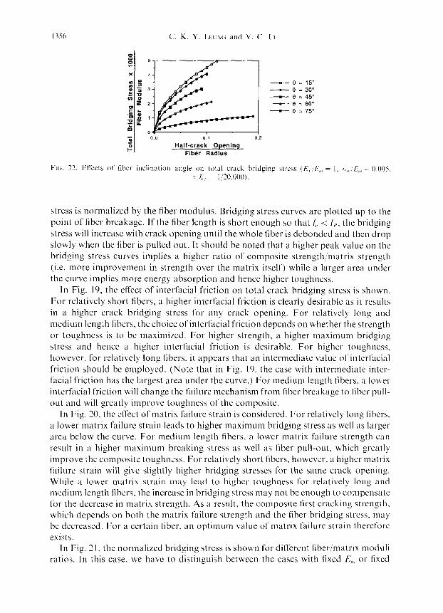
1356 C. K. Y. LEI:NC; and V. C. L.I
0
00 01 0.2
Halt-crack Opening Fiber Radius
- e = 150 - 9 = 30” - e I 450 - 0 = 60”
- 0 3 75”
FIG. 27. Etrccts of liber inclination angle on total crack bridging ctrcas (E, ‘f,,, = I. m,,,‘~,,, : 0.005. T E, = I ‘20,000).
stress is normalized by the fiber modulus. Bridging stress curves are plotted up to the point of fiber breakage. If the fiber length is short enough so that I(, < I,,, the bridging stress will increase with crack opening until the whole fiber is debonded and then drop slowly when the fiber is pulled out. It should be noted that a higher peak value on the bridging stress curves implies a higher ratio of composite strength/matrix strength (i.e. more improvement in strength over the matrix itself) while a larger area under the curve implies more energy absorption and hence higher toughness.
In Fig. 19, the effect of interfacial friction on total crack bridging stress is shown, For relatively short fibers, a higher interfacial friction is clearly desirable as it results in a higher crack bridging stress for any crack opening. For relatively long and medium length fibers. the choice of interfacial friction depends on whether the strength or toughness is to be maximized. For higher strength, a higher maximum bridging stress and hence a higher interfacial friction is desirable. For higher toughness, however, for relatively long fibers, it appears that an intcrmediatc value of interfacial friction should be employed. (Note that in Fig. 19, the case with intermediate inter- facial friction has the largest area under the curve.) For medium length fibers, a lower interfacial friction will change the failure mechanism from liber breakage to libcr puli- out and will greatly improve toughness of the composite.
In Fig. 30, the effect oT matrix failure strain is considered. For relatively long fibers. a lower matrix failure strain leads to higher maximum bridging stress as well as larger area below the curve. For medium length fibers. a lower matrix failure strength can result in ;I higher maximum breaking stress as well as fiber pull-out. which greatly improve the composite toughness. For relatively short fibers, however, a higher matrix failure strain will give slightly higher bridging stresses for the same crack opening. While a lower matrix strain may lcad to higher toughness for relatively long and medium length libers, the increase in bridging stress may not be enough to compcnsatc for the decrease in matrix strength. As a result, the composite first cracking strength, which depends on both the matrix failure strength and the fiber bridging stress. may be decreased. For a certain fiber. an optimum value of matrix failure strain thercforc exists.
In Fig. 2 I, the normalized bridging stress is shown for different fiber/matrix moduli ratios. In this case, we have to distinguish between the cases with fixed E,,, or fixed

Crack bridging by inclined fibers 1357
E,. In Fig. 21, the bridging stress is normalized with fiber modulus. If the matrix stiffness is fixed and the fiber modulus increased, the actual maximum bridging stress (without being normalized) as well as the area under the curve will both increase with fiber modulus for all fiber lengths. For a fixed matrix, the use of a stiffer fiber is therefore always desirable. If the fiber modulus is fixed, a stiffer matrix (lower E,/E,,,)
will provide higher bridging stress for relatively short fibers while a softer matrix (higher E,/E,,,) will result in higher maximum bridging stress and higher absorbed energy for relatively long and medium length fibers. However, for a fixed matrix failure strain, a lower matrix stiffness implies a lower failure strength of the matrix. Again, the improvement in crack bridging stress under such cases may not be enough to compensate for the weaker matrix. Therefore, for relatively long and medium length fibers. if the fiber modulus is fixed, the matrix modulus has to be carefully chosen.
In Fig. 22, the change of bridging stress with inclination angle is considered. For a higher inclination angle, the maximum bridging stress decreases. The total bridging stress versus crack opening curve for an inclined fiber, in comparison to that of an aligned fiber, is qualitatively shown in Fig. 23. The maximum bridging stress, the crack opening before fiber breakage and the total area under the curve are all higher for the aligned fiber. The results imply that the total bridging stress is mainly con- tributed by the debonding of fibers. Bending simply enhances the occurrence of fiber breakage and impairs composite performance. Inclination of brittle fibers can therefore weaken the composite. The trend of change in bridging stress with angle can be explained as follows. For a certain crack opening, provided fiber breakage has not yet occurred, the bridging stress is lower for a higher angle of inclination. This is because the bridging stress for composites (with micro-properties lying within practical ranges) is usually dominated by the debonding component which is proportional to (cos 0)“. The decrease in cos 8 with inclination angle thus accounts for the decrease in maximum bridging stress. The crack opening at maximum bridging stress decreases initially with angle and then increases. This is because the maximum strain on the fiber due to bending is relatively low for small and large angles but is most significant at medium angles (see Figs 16 and 17).
As a summary, in brittle fiber reinforced matrix composites, bridging stresses arising from fiber bending are usually not enough to compensate for the decrease in debonding
Bridging stress
Crack Opening
FIG. 23. Reduction of crack bridging stresses due to fiber inclination

135x C‘. K. Y. LH.YG kind V. C. LI
component due to fiber in~iin~~tion and fiber breakage. However. when random fiber composites are used due to the processing di~culties associated with producing aligned fiber composites (such as in parts of complex shapes or when very small whiskers are employed), the choice ofoptimal micro-parameters depends on the length of fiber employed as well as whether the strength or toughness is to be maximized. The micromechanical models decribed in this paper provide a quantitative means to assess the effect of various microscopic parameters on crack bridging stress from inclined fibers and forms an essential part of the ultimate goal of developing qL~~ntit~~tive optimization guidelines for random fiber composites.
6. COMPARISON OF MODEL PREIXCTION WITH EXPERIMWTAL RESULTS
To verify the model developed in this investigation, a set of experimental data on the maximum bridging force from inclined fibers (PIGGOTT. 1974) is compared with model predictions. The specimen tested by Piggott is shown in Fig. 2421. Two glass fiber bundles (0.76 mm diameter). at the same inclination angle but in opposite directions, are embedded in two blocks of a polyester resin matrix separated by a
/’ _I
Gap about Size of Fiber Diameter
(a)
pe + ( Load at
Fiber Breakage)
(b) 1.2
1 - Gap Not Consldered
2 - Gap Considered
3 - Assume 10% Higher Bundle Strength in Bending
00 0 28 40 6”
ANGLE @
FIG;. 24. (a) Cihss fiber bundle:polyrstcr spec~mcn tested by Piggott. (b) Results f’rotn the test and prediction from our model.

Crack bridging by inclined fibers I359
small gap about the size of the fiber diameter. Here, both fiber and matrix are brittle and so the assumptions of our model hold. For a fiber inclination II, the applied load P,, that causes fiber breakage corresponds to the maximum possible bridging force provided by a single fiber at that inclination. In the experiment, P,, is measured and normalized with the breaking load of an aligned fiber PO. The normalized bridging force P,,/Po is then plotted against the fiber inclination angle 0. Results are shown as squares in Fig. 24b.
Micro-properties of the glass fiber bundle/polyester system are given in FILA et al. (1972). The bundle consists of 78% fibers and the bundle modulus is 55 GPa. The bundle strength, obtained from direct tension test, is 1.35 GPa. The fiber/matrix interfacial strength T. is found to be 17 MPa (average value). The properties of the polyester are not given. However, as typical of most polyesters, we take a modulus of 2 GPa and a failure strain of 2%. Since Et/E,,, is much greater than 6 in this case. the fiber can be treated as rigid. Foundation properties for El/E,,, = 6 are used.
Curves for P,,/Po are generated with the above values for the composite micro- properties. For each inclination angle, the maximum bridging stress u,, is obtained and normalized with the fiber strength cro (note, PO/P,, = o,,/oo). Three separate curves are generated. The first two curves (marked 1 and 2 in Fig. 24b) are generated for the case neglecting the presence of a gap between the two blocks (curve 1) and the case considering its presence (curve 2). It is noted that the gap does not have a significant effect on the bridging stress as the two curves are almost indistinguishable. The curves, though always underestimating experimental results, generally lie within 10 to 15% of experimental values. Since the curves are obtained directly from mea- sured properties of fiber and interface and reasonable values for matrix properties without using any empirically fitted parameters, the close agreement is very encour- aging. If one takes into consideration the statistical nature of fiber bundle failure and assumes a higher failure strength in bending than in direct tension (due to the smaller volume of material under high stress), less strength decrease with angle 0 and even closer agreement with experimental results is expected. Curve 3 is obtained by assuming that the fiber strength increases by 10% for all inclination angles. Excellent agreement can then be obtained. The close agreement between experimental results and theoretical predictions provides support to the validity of the micromechanical model developed in this work.
7. CONCLUSION
In this paper, a new micromechanical model for the determination of crack bridging stress in random brittle fiber reinforced brittle matrix composites has been developed. Prediction of maximum bridging stress for inclined fibers based on the present model is shown to be in good agreement with experimental results. The present micro- mechanical model provides a means to quantitiatively investigate the effect of various microscopic parameters on the crack bridging stress from inclined fibers and con- tributes to the ultimate goal of developing a general set of quantitative optimization guidelines for random fiber reinforced brittle matrix composites.

I360 C. K. Y. LE~JX(; and V. C. LI
REFERENCES
AVESTON. J.. COOPEK, G. A. and KIILLY, A.
Cooti, J. and GOKLXIN, J. E. EVANS. A. G.. HI:. M. Y.
and HCJX-HINSON:. J. W. FILA, M.. BREDIN, C. and
Prc;c;orr. M. R. HANNANT. D. J., HUGHES, D. C.
and KIXLY, A. KENDAI.L. K., AL~ORII N. McN.
and BIRCHALL. J. D.
LtUNG, c. K. Y.
LEUNC;. C. K. Y. and LI, V. C. LEUN~;, C. K. Y. and LI, V. C. LI, V. C. and LHUNC;, C. K. Y. LI, V. C.. WANG, Y. and
MARSHALL. D. B., Cox. B. N. and EVANS. A. G.
MORTON, .I. and GROVES, G. W. PIC;(;OTT, M. R. POULOS. H. G. and DAVIS. E. H.
SEVEKN, R. T. 1970 TIMOSHENKO. S. P 1976
1971
1964 1989
1972 J. Mtrt. Sci. 7, 983.
1983 Phil. Trans. R. Sot. Lonci. A310, 175
1987
I990
1989 1990 1991 1990
1985
1974 1974 1974
T/w Propcrtks o/’ Fihre Cornpositcs (Conference Proceedings), p. 15. IPC Science and Tcch- nology Press. Guildford, U.K.
Proc. R. SW. Loncl. A282, 50X. J. Am. C‘c>rr~,?~. So<,. 72, 2300.
Arlr~rncrtl Sfruc~iurd Ccwmic~s (MRS Symposium Proceeding), Vol. 78, p. 189. Materials Research Society, Pittsburgh, PA.
Mic.ror?lc,c,liLini~~i~ Modding of’ Sl10rtyshrr
Rcinfhrcd Cwm~ics. Ph.D. Thesis. Dept. of Civ. En&.. MIT.
CrrLlnz. Engng sc,i. Proc. 10, I 164. C0wywxite.s 21, 305. Submitted to ASC’E J. Eng. Mcch. C‘omposirc~s 2 1 , I 32
Acta Mrrrrll. 33, 20 I3
.I. Mar. Sci. 9, 1436. J. Mech. Pl7y.v. Solids 22, 457. Elastic, Solutiom for Soil uf7d Rock Mcchrlnic~.~.
John Wiley, New York. J. 3%. Anul. 5, 239. Shwgth of’ hlutrr-ids, Purl I I. Adw~rcwl (3rd
Edition). Van Nostrand Reinhold, Scar- borough. CA.
APPENDIX: DETERMINATION OF H, FOR FINITE ELEMENT MESH
To determine If ,, we have to compare the displacement below an infinite load strip to that below a finite load strip. This appendix covers the mathematical details of this procedure.
Detcrminution of’ displucwnrnt hrlow an ir$inifr load strip
A section of an infinite load strip is shown in Fig. Al with the coordinate axes and the geometric dimensions required in the following calculations.
From POULOS and DAVIS (1974), the stresses at a point a distance z below the center line of the load strip are given by
0; = [p/n][x+sin ~(1, (A. 1)
0, = [P/7c][x-sin ~(1. (A.?)
Under plane strain conditions,
fJ,. = I@, +rr,] = 2\‘[p@]s(. (A.3)
where r, defined in Fig. A 1, is given by
tan x = hi:. (A.4)

Crack hridping by inclined fiherr 1361
Displacement u z = 0
FIN. Al. Diagram for the calculation of displacement below an infinite load strip
Assuming the ;-displacement u, equals zero at a point H, below the center line of the strip, the displacement p_ right below the center line is given by
p;= ’ s
,:’ [a;/E,,,-vrr,/E,,,-v’(rr,+a,);E,,,]d;. (A.3
Substituting (A.l))(A.4) into (A.5). we have
P: = ]/7(2h)(f -~‘)ILI~(H,IbL
where
(A.@
F(H,/h) = (l/rc)[[(l -v-2v’)/(l -v2)](H,/h) tan ’ (h/H,)+ln [I +(H,/h)‘]].
Detmninution of size of’,finite loud strip hrbcv fiber
Let 2h be the width of the strip, which is equal to the fiber diameter 2r. The length of the strip, L, is chosen so that the reaction force from the matrix on the fiber at a distance L from the crack face is less than l/200 times the maximum reaction force (which is the reaction force at the fiber exist point).
To estimate L, we have to know /3 and k,,. k,,, is dependent on L and so we have to choose L first and then iterate to see if the chosen L is good.
From POULOS and DAVIS (1974), the average displacement below a finite load strip is given
by
Pz = ](I _l’“)/E,,,l(P)(2h)(,~,(L/26). (A.7)
By definition, k,,,p, = force/unit length of strip = (p)(2h)
k,, = E,J[(t -~%,(L/2@1.
For L/(2h) = 9, frzr[L/(2h)] = 2.182 (from Poulos and Davis). We assume E,,, = O.lE, to obtain a lower bound for /I. Also, $1 is taken to be 0.25.
[j = [k,J(4E,I)] ‘.‘I
= [KAnE,(I -v')l,,,(Ll(2h))ll""(llr) = 0.3532/r. (A.@
For a beam bent at one end, the reaction force F(x) changes with the distance along the beam, x, according to

I362
Note that
C. K. Y. LI:LW and V. C. LI
F(.u) = F(O)e “’ [cos /I.y-[{I/,/( 1 +/i/,)]sin p_\-1.
Therefore. at .c = I,.
lcos /I.\-- [p/,,:( I +/j/,)1 sin /j.\-1 < 2.
IF(.Y),‘F(O)I < 2e ‘I’ = 2e ’ ‘.
Since L = 1% and h = I’.
F(.\-)/F(O) < 3.468 x IO ’ < I~200 for I>/(2h) = 9.
L = 18R. h = r is a good choice for the strip size.
(A.91
The displacement below the center point of the finite loaded strip is given in Poulos and Davis 21s
[L:‘(2h)] = 9, lC,[/,:(2h)] = 2.477.
For the displaccmcnt under the center line of the infinite strip to be of the same value. WC required. by comparing (A.6) and (A.10). that
F(/l,//I) = lo[1,.‘(2h)].
For H,;/J = 34. b-([[,,‘/I) = 2.457, which is very close to 2.477. Thcrcforc, II, is taken to bc 34h (or 34 timcs the tiber radius).