The relation between geometry, hydrology and stability of ...

ECCOMAS Congress 2016VII European Congress on Computational Methods in Applied Sciences and Engineering
M. Papadrakakis, V. Papadopoulos, G. Stefanou, V. Plevris (eds.)Crete Island, Greece, 5–10 June 2016
EFFECT OF DISC GEOMETRY ON THE DYNAMIC STABILITY OFDIRECT SPRING OPERATED PRESSURE RELIEF VALVES
(ECCOMAS CONGRESS 2016)
Istvan Erdodi1, Csaba Hos1
1Budapest University of Technology and EconomicsDepartment of Hydrodynamic Systems1111 Budapest, Muegyetem rkp. 7-9.
e-mail: [email protected], [email protected]
Keywords: pressure relief valve, dynamic stability, computational fluid dynamics, reducedorder modelling
Abstract. The most important parameter of a direct spring operated pressure relief valve is itscapacity, which is the rated flow through the valve under conditions given by the correspond-ing industrial standard. There are several phenomena due to which dynamic instabilities mayarise in the system, leading to dangerous oscillations and reduced flow rate. One of the causesof these instabilities is the acoustic coupling of the valve with its upstream piping, the math-ematical background of which has already been thoroughly investigated by the researchers atour department. As a continuation of that work, this paper focuses on the engineering appli-cations by proposing various valve disc geometries based on preliminary measurement results,and evaluating their dynamic stability performance in a wide range of parameters. Steady-stateCFD computations were performed to determine the mass flow rate and force characteristicsof the various valve discs. Through these quantities, the behaviour of each geometry was im-plemented into our one-dimensional coupled gas dynamical solver, which resolves the pipedynamics using the one-dimensional continuity-, momentum- and energy equations. The valveitself is modelled as a one degree-of-freedom oscillator. Finally, the stability maps of each ge-ometries were calculated using the gas dynamical model and it was shown that the shape of thefluid force function does indeed have a significant effect on the stable operating range.

Istvan Erdodi, Csaba Hos
1 INTRODUCTION
The main purpose of pressure relief valves is to guarantee that the pressure in the protectedsystem does not exceed a prescribed level, which is the set pressure of the valve. The otherimportant parameter is the so-called capacity, that is the rated flow through the valve understated conditions prescribed by the corresponding standard [1]. As this determines how quickthe relief process is, it is imperative from the point of safety that this mass flow rate is guaran-teed. However, certain instabilities may arise, leading to harmful vibrations and a reduction inthe flow rate.
The literature distinguishes between static and dynamic instabilities. The former involvesthe study of the governing equations of the valve — usually in a linearised form — around itsequilibrium positions [2], while the latter deals with more complicated, generally system-levelissues [3]. In this paper a dynamic instability caused by the acoustic coupling between the valveand the straight upstream piping is investigated. Previous measurements and simulation resultshave shown that the stability in this case depends on the driving mass flow rate and the lengthof the upstream piping for a given valve geometry [4, 5]. The goal of this paper is to provide anumerical method for stability analysis, and also to get an insight into the geometry-dependenceof this instability by qualitatively comparing the stability maps in the mass flow rate and pipelength plane for three different valve disc geometries.
2 THEORETICAL BACKGROUND
The valve disc can be modelled as a one degree-of-freedom oscillator, for which the equationof motion is
mxv + kxv + s(xv + xp) = Ftotal, (1)
where m is the reduced mass of the moving parts, xv is the valve lift, k is the damping coeffi-cient, s is the spring stiffness, xp is the pre-compression of the spring and Ftotal is the total forceacting on the valve disc. The latter is the sum of the pressure, momentum and viscous forces —its modelling poses a significant challenge, as the momentum and viscous components cannotbe accurately approximated by analytical means without a detailed knowledge of the flow-field.To circumvent this, the so-called effective area was employed during our calculations [6, 7, 8],that is
Ftotal = Aeff(xv)(pv − pb), (2)
where Aeff(xv) is the effective area function, pv is the pressure upstream of the valve and pb
is the back pressure. This assumes that the total force can be expressed by multiplying thepressure drop on the valve by an equivalent area, which depends only on the valve lift. Notethat this approach neglects any unsteady effects, such as those from a non-zero valve velocity.The effective area functions differ for all valve geometries, and as such these are unknown asof now. However, since both the momentum and viscous forces equal zero if the valve is in aclosed position, the effective area at that point equals the cross-sectional area of the seat.
During dynamically unstable cases, it is possible that the valve hits the seat. The resultantimpact is treated as a mapping in the model with
xv+ = −rxv
−, (3)
where xv− and xv
+ are the valve velocities before and after the impact and r is the coefficientof restitution. For convenience, let the seat be located at xv = 0. Bouncing occurs if the valvevelocity is above a set threshold (x−v ≥ xth), or the velocity is lower than the threshold and the

Istvan Erdodi, Csaba Hos
sum of all forces pushes the valve away from the seat (x−v < xth and x−v > 0). Otherwise, thevalve sticks to the seat.
The one-dimensional continuity-, momentum-, and energy equations were written for thestraight pipe section upstream of the valve, which are
∂U∂t
+∂F∂ξ
= Q, (4)
U =
ρρvρe
, F =
ρvρv2 + pρve+ pv
, Q =
0
− f(v)ρ2Dpipe
v|v|0
,
where t is the time, ξ is the spatial coordinate, ρ is the density, v is the velocity, e is the specificenergy, f is the Darcy friction factor and Dpipe is the diameter of the pipe. Preliminary testshave shown that treating the friction factor as a constant led to the erroneous estimation of thepressure drop due to the wide Reynolds number range in the pipe, and as such Blasius’ correla-tion for turbulent flows was implemented — this means that the friction factor is a function ofthe velocity.
At the ξ = 0 end an infinitely large reservoir boundary condition was set, which is realizedby prescribing the total pressure in the case of inflow to the pipe, and the static pressure other-wise. The valve boundary condition is implemented at ξ = L. The basic principle is that themass flow rate leaving the pipe must also satisfy the discharge equation for the valve. If theflow is chocked, the equation to be solved is
ρ(L, t)Apipev(L, t) = CDAref(xv)
√γρ(L, t)p(L, t)
(2
γ + 1
)γ+1γ−1
, (5)
where CD is the discharge coefficient, Aref is the reference flow-through area and γ is the ratioof specific heats. Similarly, for the non-chocked case we have
ρ(L, t)Apipev(L, t) = CDAref(xv)
√√√√2ρ(L, t)p(L, t)γ
γ− 1
((pb
p(L, t)
) 2γ
−(
pb
p(L, t)
)γ+1γ
).
(6)The discharge coefficient is unknown as of yet, while the cylindrical surface between the seatand the valve disc is taken as the reference area is, that is
Aref(xv) = Dseatπxv, (7)
whereDseat is the diameter at the seat. In our case the seat was the chamfered pipe end, thereforeDseat = Dpipe (see Figure 1(a)).
Equation (1) is solved using standard Runge-Kutta, while the Lax-Wendroff method is usedfor the discretization of equation (4). The boundary conditions were implemented with theisentropic method of characteristics.

Istvan Erdodi, Csaba Hos
(a)
60
100100
50
100
inlet
opening
open
ing
opening
wall
wall
(axi
s)(a
xis)
(b)
Figure 1: (a) The three geometries (0◦, 45◦ and 90◦ from top to bottom) with the mesh lines ata valve lift of 0.15Dpipe. (b) The number of nodes and the boundary conditions. The filledparts indicate the structured part of the mesh. (The figure is not proportional for illustration
purposes.)
3 CFD SETUP
As mentioned in the previous section, two necessary parameters are unknown due to the lackof accurate analytical methods: the effective area function and the discharge coefficient. Theirvalues were determined by means of CFD.
Simulations were conducted for three different geometries, which were generated by varyingthe collar angle (Figure 1(a)). Axisymmetric treatment of the flow field was possible due tothe simplicity of the geometry, effectively rendering the problem two-dimensional and as suchsignificantly reducing the needed computational time. This resulted in a wedge-shaped domainwith a central angle of 5◦, meaning that the extensive quantities — namely the mass flow rateand the total force acting on the valve — had to be rescaled for the full-sized valve.
The meshes were automatically generated for all geometries and lifts, with the number ofnodes varying between 80 000 and 85 000. They consist of both structured and unstructuredregions according to Figure 1(b) (the modelled domain is similar for the 0◦ and 90◦ cases). Themeshes were created in ICEM. The inner diameter of the pipe was 40.2 mm, the upstream pip-ing had a length of 10Dpipe and the valve lift was varied between 0.05Dpipe and 0.30Dpipe.
Total pressures between 2 and 6 bar were prescribed at the inlet boundary condition with astatic temperature of 293 K. The pressure was set to 1 bar at the opening boundary condition,which corresponds to static or total pressure for outflow and inflow, respectively. The tempera-ture was also 293 K. The medium was air with the ideal gas law and the k-ε turbulence model.The simulations were done in CFX environment. The High Resolution scheme was employedfor the advection terms and the turbulence model, and the Second Order Backward Euler for
Istvan Erdodi, Csaba Hos
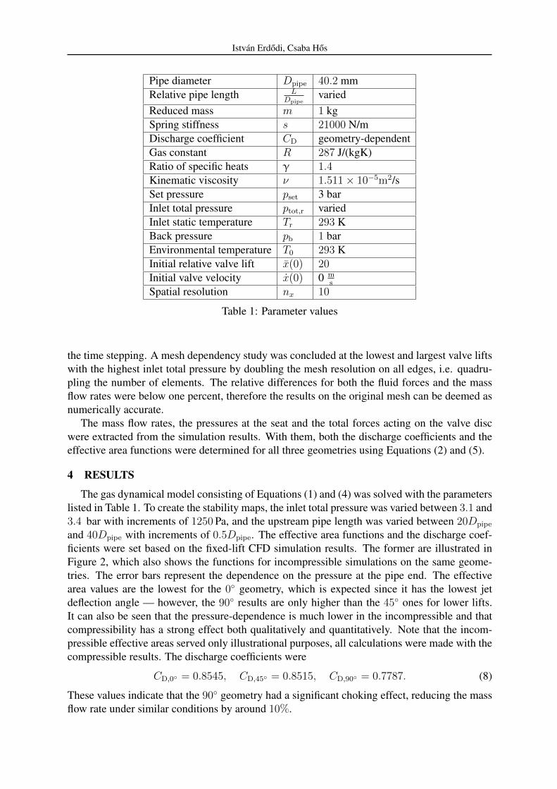
Pipe diameter Dpipe 40.2 mmRelative pipe length L
Dpipevaried
Reduced mass m 1 kgSpring stiffness s 21000 N/mDischarge coefficient CD geometry-dependentGas constant R 287 J/(kgK)Ratio of specific heats γ 1.4Kinematic viscosity ν 1.511× 10⁻⁵m2/sSet pressure pset 3 barInlet total pressure ptot,r variedInlet static temperature Tr 293 KBack pressure pb 1 barEnvironmental temperature T0 293 KInitial relative valve lift x(0) 20Initial valve velocity x(0) 0 m
s
Spatial resolution nx 10
Table 1: Parameter values
the time stepping. A mesh dependency study was concluded at the lowest and largest valve liftswith the highest inlet total pressure by doubling the mesh resolution on all edges, i.e. quadru-pling the number of elements. The relative differences for both the fluid forces and the massflow rates were below one percent, therefore the results on the original mesh can be deemed asnumerically accurate.
The mass flow rates, the pressures at the seat and the total forces acting on the valve discwere extracted from the simulation results. With them, both the discharge coefficients and theeffective area functions were determined for all three geometries using Equations (2) and (5).
4 RESULTS
The gas dynamical model consisting of Equations (1) and (4) was solved with the parameterslisted in Table 1. To create the stability maps, the inlet total pressure was varied between 3.1 and3.4 bar with increments of 1250 Pa, and the upstream pipe length was varied between 20Dpipe
and 40Dpipe with increments of 0.5Dpipe. The effective area functions and the discharge coef-ficients were set based on the fixed-lift CFD simulation results. The former are illustrated inFigure 2, which also shows the functions for incompressible simulations on the same geome-tries. The error bars represent the dependence on the pressure at the pipe end. The effectivearea values are the lowest for the 0◦ geometry, which is expected since it has the lowest jetdeflection angle — however, the 90◦ results are only higher than the 45◦ ones for lower lifts.It can also be seen that the pressure-dependence is much lower in the incompressible and thatcompressibility has a strong effect both qualitatively and quantitatively. Note that the incom-pressible effective areas served only illustrational purposes, all calculations were made with thecompressible results. The discharge coefficients were
CD,0◦ = 0.8545, CD,45◦ = 0.8515, CD,90◦ = 0.7787. (8)
These values indicate that the 90◦ geometry had a significant choking effect, reducing the massflow rate under similar conditions by around 10%.

Istvan Erdodi, Csaba Hos
0 5 10 15 20 25 30 351
1.5
2
2.5
3
3.5
x/Dpipe [-]
Aeff/A
pipe[-]
0° compr.0° incompr.45° compr.45° incompr.90° compr.90° incompr.
Figure 2: The effective area results for both the compressible (continuous lines) andincompressible (dashed lines) cases.
The results were said to be stable if the valve lift reached the equilibrium position in adecaying manner, and unstable otherwise, i.e. when periodic non-decaying oscillations wereproduced. First, the stability map was created in the inlet total pressure and upstream pipelength plane, as these were the two varied parameters (Figure 3(a)). The boundary curves differin the three cases: for the 0◦ geometry, increasing the inlet total pressure extends the stableoperating range, while the system behaves the opposite way for the 45◦ disc. In the case of the90 deg geometry, the boundary of stability is seemingly independent of the inlet total pressure.This shows that the accurate calculation of the fluid forces introduces not just qualitative, butalso quantitative differences in regarding the boundary of stability.
The corresponding industrial standard [1] and the literature [9] usually discusses stability asa function the driving mass flow rate and pipe length. This map can be seen in Figure 3(b).Similar tendencies can be observed to those mentioned above regarding the shape of the curves,however, the difference in the mass flow rates makes the comparison ambiguous — it is possiblethat at higher flow rates the 0◦ curve becomes flatter (or even decreasing). The lower flow ratescan be traced back to the lower effective area values (see Figure 2) as lower fluid forces do notproduce as much valve lift.
5 CONCLUSIONS
This study employed a relatively simple, one-dimensional model for computing the valve re-sponse for a given inlet total pressure. Steady-state CFD simulations were conducted for threedifferent valve disc geometries in order to obtain their force characteristics and discharge coef-ficients. With these, their specifics were implemented into the reduced model and a parameterstudy was conducted in the mass flow rate and the inlet total pressure plane. It was shownthat even slight changes in the disc geometry can have a significant effect on both the stableoperating range and the resulting mass flow rate.

Istvan Erdodi, Csaba Hos
3.1 3.12 3.14 3.16 3.18 3.2 3.22 3.24 3.26 3.28 3.30
5
10
15
20
25
30
35
40
ptot [bar]
L/D
pipe[-]
0°45°90°
(a)
0 0.1 0.2 0.3 0.4 0.5 0.6 0.7 0.80
5
10
15
20
25
30
35
40
m [kg/s]
L/D
pipe[-]
0°45°90°
(b)
Figure 3: Boundaries of stability in the total pressure and pipe length (a) and mass flow rateand pipe length (b) planes. In both cases instability was observed above the boundaries.
Istvan Erdodi, Csaba Hos
6 ACKNOWLEDGEMENTS
This project was supported by the OTKA Grant K116549 of Csaba Hos. The authors wouldalso like to express their thanks to Zalan Bucsu and Szabolcs Santa for providing their incom-pressible simulation results and numerical meshes.
REFERENCES
[1] American Petroleum Institute, “API Standard 520: Sizing, Selection, and Installation ofPressure-relieving Devices, Part II—Installation,” 2015.
[2] C. Bazso and C. Hos, “On the static instability of liquid poppet valves,” Periodica Polytech-nica Mechanical Engineering, vol. 59, no. 1, pp. 1–7, 2015.
[3] C. B. Domnick, F.-K. Benra, D. Brillert, and C. Musch, “Modification of a steam valvediffuser for enhanced full load and part load operation using numerical methods,” in Pro-ceedings of CMFF’15, (Budapest), 2015.
[4] A. Beune, J. Kuerten, and M. van Heumen, “CFD analysis with fluid-structure interactionof opening high-pressure safety valves,” Computers and Fluids, vol. 64, pp. 108–116, 2012.
[5] O. Frommann and L. Friedel, “Analysis of safety relief valve chatter induced by pressurewaves in gas flow,” Journal of Loss Prevention in the Process Industries, vol. 11, no. 4,pp. 279–290, 1998.
[6] V. Dossena, F. Marinoni, F. Bassi, N. Franchina, and M. Savini, “Numerical and experi-mental investigation on the performance of safety valves operating with different gases,”International Journal of Pressure Vessels and Piping, vol. 104, pp. 21–29, 2013.
[7] C. J. Hos, A. R. Champneys, K. Paul, and M. McNeely, “Dynamic behavior of direct springloaded pressure relief valves in gas service: Model development, measurements and insta-bility mechanisms,” Journal of Loss Prevention in the Process Industries, vol. 31, no. 1,pp. 70–81, 2014.
[8] P. Moussou, R. J. Gibert, G. Brasseur, C. Teygeman, J. Ferrari, and J. F. Rit, “Instabilityof pressure relief valves in water pipes,” Journal of Pressure Vessel Technology, vol. 132,no. 4, p. 041308, 2010.
[9] C. Hos, A. Champneys, K. Paul, and M. McNeely, “Dynamic behaviour of direct springloaded pressure relief valves in gas service: II reduced order modelling,” Journal of LossPrevention in the Process Industries, vol. 36, pp. 1–12, 2015.