EFFECT OF DIFFERENT TYPE OF POLYMER...
25
EFFECT OF DIFFERENT TYPE OF POLYMER CONCENTRATION ON ASYMMETRIC POLYSULFONE MEMBRANE FOR CO 2 /CH 4 SEPARATION NUR AMIRA BINTI ABDULLAH Thesis submitted in fulfillment of the requirements for the award of the degree of Bachelor of Chemical Engineering (Gas Technology) Faculty of Chemical & Natural Resources Engineering UNIVERSITI MALAYSIA PAHANG DECEMBER 2010
Transcript of EFFECT OF DIFFERENT TYPE OF POLYMER...

EFFECT OF DIFFERENT TYPE OF POLYMER CONCENTRATION
ON ASYMMETRIC POLYSULFONE MEMBRANE
FOR CO2/CH4 SEPARATION
NUR AMIRA BINTI ABDULLAH
Thesis submitted in fulfillment of the requirements
for the award of the degree of
Bachelor of Chemical Engineering (Gas Technology)
Faculty of Chemical & Natural Resources Engineering
UNIVERSITI MALAYSIA PAHANG
DECEMBER 2010

vii
ABSTRACT
The objective of this study is to developed polysulfone (PSU) asymmetric membrane
for gas separation and to identify the concentration of polysulfone in dope solution to
produce high selectivity membrane for CO2/CH4 gas separation. Polysulfone was
selected as the polymer material in this research since it is glassy type polymer that
exhibit good mechanical properties compare to others while 1-Methyl-2-Pyrrolidone
(NMP) is chosen as the solvent because it is low toxicity and completely miscible
with water, organic acid and alcohol. Polysulfone asymmetric membrane was
prepared by mixing a dope, where polysulfone polymer was mixed with 1-Methyl-2-
Pyrrolidone (NMP). Three sample of solution was prepared with different type of
concentration of polysulfone polymer which is 20 wt%, 25 wt% and 30 wt%
respectively. Before perform gas permeation test, polysulfone membrane was coating
with PDMS and n-hexane with the composition 3 wt% and 97 wt% respectively.
Permeation test was carried out by using single gas permeation test by testing gas
carbon dioxide (CO2) and methane (CH4). The membranes were characterized by
using Scanning Electron Microscope (SEM) and Fourier Transform Infrared
Spectroscopy (FTIR). Through SEM analysis, the morphology and structure of the
membrane at 20 wt% concentration of polysulfone shows structural pores using 1000
magnification. Membranes with 30 wt% of PSU exhibits the most selective
membrane with selectivity about 2.619 while membrane with 20 wt% shows the
lowest selectivity that is 1.22. This is because the increasing polysulfone polymer
concentration resulted a denser and thicker skin layer of membrane so that the
membrane with high polysulfone concentration become more selective but less
permeability to the gas separation.

viii
ABSTRAK
Objektif kajian ini adalah untuk menghasilkan membrane asimetrik polysulfone
untuk tujuan pengasingan gas CO2/CH4 dan untuk mengenal pasti kepekatan polymer
yang dapat menunjukkan ciri-ciri selektif yang paling baik. Polysulfone dipilih
sebagai material untuk polymer dalam penghasilan membrane kerana ia
menunjukkan ciri-ciri mekanikal yang baik berbanding polymer lain manakala 1-
Methyl-2-Pyrrolidone (NMP) dipilih sebagai pelarut kerana ianya kurang toksid dan
dapat terlarut sepenuhnya bila bergabung dengan air. Membrane asimetrik
Polysulfone disediakan dengan mencampurkan larutan dope, dimana polysulfone
dicampur bersama 1-Methyl-2-Pyrrolidone (NMP). Tiga jenis sampel untuk larutan
disediakan pada kepekatan polymer yang berbeza iaitu masing masing 20 wt%, 25
wt% and 30 wt% . Sebelum menjalankan ujian penyerapan gas, polysulfone
membrane dilapisi menggunakan PDMS and n-hexane dengan kandungan material
masing-masing 3 wt% and 97 wt%. Ujian penyerapan gas dijalankan menggunakan
alat ujian penyerapan gas dengan menguji gas karbon dioksida (CO2) dan methane
(CH4). Kesemua membrane menjalani ujian menggunakan Scanning Electron
Microscope (SEM) and Fourier Transform Infrared Spectroscopy (FTIR) untuk
melihat struktur membrane. Melalui analysis SEM, struktur membrane pada
kepekatan polysulfone 20 wt% menunjukkan struktur kaviti yang besar pada
magnifikasi 1000. Membrane dengan kepekatan polymer 30 wt% menunjukkan ciri
yang paling selektif dengan nilai selektiviti 2.619 manakala membrane dengan
kepekatan 20 wt% menunjukkan selektiviti paling rendah iaitu pada 1.22. Hal ini
kerana penambahan kepekatan polymer menyebabkan struktur membrane menjadi
semakin padat dan tebal dan menyebabkan membrane menjadi semakin selektif.

ix
TABLE OF CONTENT
CHAPTER TITLE PAGE
AKNOWLEDGEMENT vi
ABSTRACT vii
TABLE OF CONTENTS ix
LIST OF TABLES xii
LIST OF FIGURES xiii
1 INTRODUCTION
1.1 Background of Study 1
1.2 Problem Statements 2
1.3 Objectives 3
1.4 Scope of studies 3
2 LITERATURE REVIEW
2.1 Membrane Separation Process 5
2.2 Type of Membrane
2.2.1 Ultrafiltration 7
2.2.2 Microfiltration 8
2.2.3 Reverse Osmosis 9
2.3 Membrane Module
2.3.1 Plate and Frame Module 10
2.3.2 Tubular Module 11
2.3.3 Hollow Fiber Module 13

x
2.4 Advantages of Membrane Module
2.4.1 Energy Saving 15
2.4.2 Clean Energy 15
2.4.3 The Ability of Connection to Other Process 16
2.4.4 Good Weight and Space Efficiency 16
2.4.5 Operational Simplycity and High Reliability 16
2.4.6 Lower Capital Cost 17
2.4.7 Lower Operating Cost 17
2.4.8 Deferred Capital Investment 17
2.5 Membrane in Gas Separation
2.5.1 History and Introduction 18
2.5.2 Permeability and Selectivity
2.5.2.1 Gas Permeation Test 20
2.5.2.2 Scanning Electron Microscope 22
2.5.2.3 Fourier Transform Infrared (FTIR) 23
2.5.3 Polymer as Membrane Material 24
2.6 Asymmetric Membrane 25
2.6.1 Solution Diffusion Mechanism 28
2.7 Influence of Various Parameters on Membrane
Performance 30
3 METHODOLOGY
3.1 Materials
3.1.1 Polysulfone 32
3.1.2 1-Methyl-2-Prrolidone (NMP) 33
3.1.3 Physical properties of Non-Solvent Additives
And Coagulation Bath 33
3.2 Research background 34
3.3 Solution Dope Preparation 34
3.4 Membrane Casting 35
3.5 Gas Permeation Test 36

xi
3.6 Membrane Characterization 37
3.6.1 Scanning Electron Method (SEM) 37
3.6.2 Fourier Transform Infrared 37
4 RESULTS AND DISCUSSION
4.1 Results 38
4.1.1 Effect of Polysulfone Concentration on Gas
Separation Performance 42
4.1.2 Effect of Polysulfone Concentration on
Morphology Of Asymmetric Polysulfone
Membrane 49
4.1.3 Effect of Polysulfone Concentration on
Characteristic Of Asymmetric Membrane
Functional Group 52
5 CONCLUSIONS AND RECOMMENDATIONS
5.1 Conclusions 54
5.2 Recommendations 55
REFERENCES 56
xii
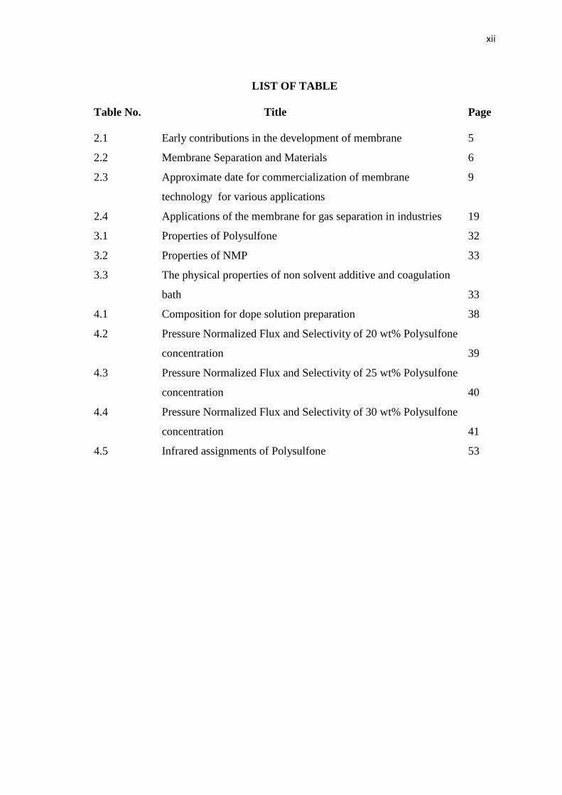
LIST OF TABLE
Table No. Title Page
2.1 Early contributions in the development of membrane 5
2.2 Membrane Separation and Materials 6
2.3 Approximate date for commercialization of membrane 9
technology for various applications
2.4 Applications of the membrane for gas separation in industries 19
3.1 Properties of Polysulfone 32
3.2 Properties of NMP 33
3.3 The physical properties of non solvent additive and coagulation
bath 33
4.1 Composition for dope solution preparation 38
4.2 Pressure Normalized Flux and Selectivity of 20 wt% Polysulfone
concentration 39
4.3 Pressure Normalized Flux and Selectivity of 25 wt% Polysulfone
concentration 40
4.4 Pressure Normalized Flux and Selectivity of 30 wt% Polysulfone
concentration 41
4.5 Infrared assignments of Polysulfone 53

xiii
LIST OF FIGURES
Figure No. Title Page
2.1 Membrane and modules sales for different process application 7
2.2 Schematic of the plate and frame module 11
2.3 Tubular Module for Ultrafiltration 12
2.4 Schematic diagram of tubular module 12
2.5 Schematic representation of shell side feed type hollow fibre membrane
module 13
2.6 Schematic representation of bore side feed type of hollow fibre
membrane module 14
2.7 Milestone in the development of membrane for gas separation 19
2.8 Schematic diagram of gas permeation test set up 21
2.9 Schematic diagram of scanning electron microscope 23
2.10 Structure of polysulfone and raw material 25
2.11 Asymmetric membrane structure consists of porous and nonporous layer 26
structure
2.12 SEM image of an asymmetric polysulfone membrane by solution casting
method 26
2.13 Step on preparations of dry/wet phase inversion 27
3.1 Research design 34
3.2 Dope preparation system 35
3.3 Schematic diagram for gas permeation test 36
4.1 Graph of average pressure normalized flux (GPU) of CO2 versus pressure
(bar) at different type of concentration 42
4.2 Graph of average pressure normalized flux (GPU) of CH4 versus pressure
(bar) at different type of polysulfone concentration 43
4.3 Graph of average pressure normalized flux of CO2 versus polysulfone 44
concentration at different pressure
4.4 Graph of the average pressure normalized flux (GPU) of CH4
versus polymer concentration (wt%) at different pressure 46
4.5 Graph of selectivity versus pressure (bar) at different type of polysulfone
concentration 47

xiv
4.6 SEM of the cross section of the prepared polysulfone asymmetric membrane
for CO2/CH4 gas separation: (a) M1 at 300 magnifications; (b) M2 at 1K
magnifications; (c) M3 at 1K magnifications 50
4.7 FTIR spectra of polysulfone asymmetric membrane 5

CHAPTER 1
INTRODUCTION
1.1 BACKGROUND OF STUDY
In natural gas processing, it involved the separation of some of the components
contain in natural gas such as water, acid gas and heavy carbon in order to satisfy the
commercial specifications. Carbon dioxide (CO2) which falls into category of acid gases
is commonly found in natural gas stream at level as high as 80 percent. In combination
with water, it is highly corrosive and rapidly destroys pipeline and equipment unless it
is particularly removed or expensive construction materials are used. Carbon dioxide
reduces the heating value of natural gas. In LNG plant, carbon dioxide must be removed
to prevent freezing in low temperature chiller.
There are various types of acid gas removal process such as solvent absorption,
solid adsorption, direct conversion, cryogenic fractionators and membranes. This
research will focus on membranes separation process.
The membrane processes have the some characteristic as the alternative
technology. According to Baker (2000), membrane technology is continuity and
simplicity process compared to conventional separation technology. Besides, this
technology is flexibility in designed because it can be combined with each other and
with other separation technologies to meet complex demand in separation technology.
The other characteristic of membrane technologies that give significant advantages to
the industries is the compactness of it design that suitable for the plant that limited in
area.
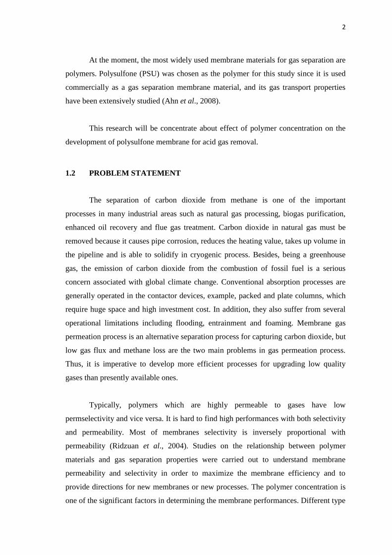
2
At the moment, the most widely used membrane materials for gas separation are
polymers. Polysulfone (PSU) was chosen as the polymer for this study since it is used
commercially as a gas separation membrane material, and its gas transport properties
have been extensively studied (Ahn et al., 2008).
This research will be concentrate about effect of polymer concentration on the
development of polysulfone membrane for acid gas removal.
1.2 PROBLEM STATEMENT
The separation of carbon dioxide from methane is one of the important
processes in many industrial areas such as natural gas processing, biogas purification,
enhanced oil recovery and flue gas treatment. Carbon dioxide in natural gas must be
removed because it causes pipe corrosion, reduces the heating value, takes up volume in
the pipeline and is able to solidify in cryogenic process. Besides, being a greenhouse
gas, the emission of carbon dioxide from the combustion of fossil fuel is a serious
concern associated with global climate change. Conventional absorption processes are
generally operated in the contactor devices, example, packed and plate columns, which
require huge space and high investment cost. In addition, they also suffer from several
operational limitations including flooding, entrainment and foaming. Membrane gas
permeation process is an alternative separation process for capturing carbon dioxide, but
low gas flux and methane loss are the two main problems in gas permeation process.
Thus, it is imperative to develop more efficient processes for upgrading low quality
gases than presently available ones.
Typically, polymers which are highly permeable to gases have low
permselectivity and vice versa. It is hard to find high performances with both selectivity
and permeability. Most of membranes selectivity is inversely proportional with
permeability (Ridzuan et al., 2004). Studies on the relationship between polymer
materials and gas separation properties were carried out to understand membrane
permeability and selectivity in order to maximize the membrane efficiency and to
provide directions for new membranes or new processes. The polymer concentration is
one of the significant factors in determining the membrane performances. Different type

3
of polymer concentration used in the casting solution result in the difference
morphology and separation performance in CO2/CH4 gas separation. In order to get high
purity of methane, so the membrane that exhibit the highest selectivity is needed to
achieved the goal.
1.3 OBJECTIVES
The objectives of this study are to develope the asymmetric polysulfone
membrane and to identify the concentration of asymmetric polysulfone membrane to
produce high selectivity membrane for CO2/CH4 gas separation.
1.4 SCOPE OF STUDIES
In order to achieve the set objectives, several scopes of work have been
identified.
a. Study of different polymer concentration to produce asymmetric
polysulfone membrane.
b. Used gas permeation test to test the develop membrane.
c. Characteristic study of membrane morphology by using Scanning
Electron Microscope (SEM).
d. Identify functional group contains in membrane by using Fourier
Transform Infrared Spectroscopy (FTIR).

CHAPTER 2
LITERATURE REVIEW
2.1 MEMBRANE SEPARATION PROCESS
A membrane is a permeable or semi-permeable phase, often a thin polymeric
solid, which restricts the motions of certain species. Generally, a membrane is a phase
or a group of phase that lies between two different phases, which is physically or
chemically distinctive from both of them and which due to its properties and the force
field applied (driving force), is able to control the mass transport between these phases
(Paul and Yampol, 1994). In simple words, membrane can be defined as a barrier
between two fluids, which allows selective transfer of some species through a driving
force.
According to Pabby (2008), membranes can be classified as homogeneous or
heterogeneous, symmetrical or asymmetrical, and porous or non- porous. Besides, they
can be organic or inorganic, liquid or solid. There are three different types of pore size
classifications: microporous (dp < 2nm), mesoporous (2nm < dp < 50nm) and
macroporous (dp > 50nm) (Mccusker and F. Liebau, 2001).
The historical development of membrane has started at eighteenth century.
Membrane technology has been developed from a laboratory technique to a large-scale
industrial application. Today membrane technology is applied in a wide range of
applications such as in water purification, food industry, dairy, pharmaceutical, textile
industry, petrochemical industry and many other applications. Table 2.1 shows some
early contributions in the development of membrane.

5
Table 2.1: Early contributions in the development of membrane (Cardew and Lew,
1994)
Contributions Membrane Process Contributors Years
Observations
Osmosis Nollet 1748
Electro osmosis Reuss, Porret 1816
Dialysis Graham 1861
Diffusion Fick 1885
Relations Osmotic pressure Van’t Hoff 1887
Electrolyte transport Nernst Planck 1889
Theoretical
considerations
Osmotic pressure
Einstein
1905
Membrane potentials Henderson 1907
Membrane equilibrium Donnan 1911
Anomalous osmosis Sollner 1930
Irreversible thermodynamics Kedern,
Katchalsky
1964
Ionic membrane Teorell 1937
Transport model Pore model Schmid 1950
Solution diffusion model Lonsdale 1965
Transport of selected species through the membrane is achieved by applying a
driving force across the membrane. This gives a broad classification of membrane
separations in the way or mechanism by which material is transported across a
membrane. The flow of material across a membrane has to be kinectically driven, by the
application of either mechanical, chemical or electric work. The driving forces are either
pressure, concentration, temperature potential. In many cases the transport rate
(permeation) is proportional to the driving force and the membrane can be categorized
in terms of an appropriate permeability coefficient. The use of driving force as means of
classification is not altogether satisfactory because apparently different membrane

6
process can be applied for the same separation, for example electrodialysis, reverse
osmosis and pervaporation in the desalination of water. All the process use membrane
which are micropous in nature.
There are the most simple form of membrane regarding mode of separation and
consist of solid matrix with defined pores ranging from 100nm to 50µm in size. Table
2.2 lists the membrane processes and the driving force.
Table 2.2: Membrane separations and materials (Matsuura, 1996)
Process Application Driving Force
Microfiltration Separation of suspended particles. Hydrostatic pressure
Ultrafiltration Concentration and purification of
solvents from
macromolecular
solutions.
Hydrostatic pressure
Nanofiltration Concentration and purification of
solvents from medium
molecular weight
solutes.
Hydrostatic pressure
Membrane
distill
ation
Desalination and concentration of
solutions.
Temperature
Electro dialysis Desalination and deacidification. Electric potential
Reverse osmosis Desalination, concentration of low
molecular weight
solutes.
Hydrostatic pressure
Gas permeation Gas separation Hydrostatic pressure
Concentration gradient
Pervaporation
Separation of azeotropes and liquid
mixtures.
Concentration gradient
Vapor pressure
Liquid membranes Separation of ions and solutes from
liquids.
Concentration
Reaction

7
Nowadays, membrane technology is becoming an established part of several
industrial processes. The technology is largely applicable in the food industry, in the
manufacture of dairy products and in the gas processing industries. Membranes
important in water industry and avoid people from suffering kidney disease. The
markets of membrane in Asia and South America are growing fast. According to study,
hemodialysis/hemofiltration alone had sales of over US 2200 million in 1998.
Reverse osmosis (RO), ultrafiltration (UF) and microfiltration (MF) had sales
over 1.8 billion dollars respectively in 1998. Membranes and modules were sold for US
400 million each year world wide for use in reverse osmosis. Ultrafiltration membranes
and modules brought about US 500 million insales in 1998 with an expected growing
rate of 10% a year. Sales of microfiltration equipment and membrane is 2.5 billion in
2008. Gas separation accounted for about US 230M. (Nunes et al, 2006). Figures 2.1
below shows the membrane and the types module sales according to the application
used.
Figure 2 .1: Membrane and Modules sales for different process application
(Nunes et al, 2006)
2.2 TYPES OF MEMBRANE PROCESS
2.2.1 Ultrafiltration
Ultrafiltration (UF) is the process that involved the separating of small particles
and dissolved molecules from fluids. The process separation is depends on molecular

8
size. The molecules with the same size can not be separated by ultra filtration. The
range of materials from 1K to 1000K molecular weight (MW) is retained by certain
ultrafiltration membranes, while salts and water will pass through. Colloidal and
particulate matter can also be retained. Materials that is significantly smaller than the
pore size rating pass through the filter and can be depyrogenated, clarified and separated
from high molecular weight contaminants. Materials larger than the pore size rating are
retained by the filter and can be concentrated or separated from low molecular weight
contaminants. Usually, the process of ultrafiltration is involved in the proteins
separating from buffer components for buffer exchange, desalting, or concentration.
Ultrafilters are also practicalin the process of removing or exchange of sugars, non-
aqueous solvents, the separation of free from protein-bound ligands, the removal of
materials of low molecular weight, or the rapid change of ionic and/or pH environment
(Munir, 2006).
2.2.2 Microfiltration
Micro filtration (MF) is the process of removing particles or biological entities
in the range of 0.025 μm to 10.0μm by passage through a microporous medium such as
a membrane filter. Membrane filters has been used for final filtration. Membrane and
depth filters offer certain advantages and limitations. They can complement each other
when used together in a microfiltration process system or fabricated device. The
retention boundary defined by a membrane filter can also be used as an analytical tool
to validate the integrity and efficiency of a system. Microfiltration also can be used in
sample preparation to remove intact cells and some cell debris from the lysate. For this
type of separation, the membrane pore size cut-offs used are typically in the range of
0.05 μm to 1.0 μm (George, 2009).
2.2.3 Reverse Osmosis
Reverse osmosis (RO) is the process of separating salts and small molecules
from low molecular weight solutes (typically less than 100 daltons) at relatively high
pressures using membranes with NMWLs of 1 kDa or lower. RO membranes are
normally rated by their retention of sodium chloride while ultrafiltration membranes are

9
characterized according to the molecular weight of retained solutes. Millipore water
purification systems employ both reverse osmosis membranes as well as ultrafiltration
membranes. Reverse osmosis systems are primarily used to purify tap water to purities
that exceed distilled water quality. Ultrafiltration systems ensure that ultrapure water is
free from endotoxins as well as nucleases for critical biological research (Munir, 2006).
The commercialization of membrane technology and the date commercialize is
summarized in table 2.3.
Table 2.3: Approximate date for commercialization of membrane technology for
various applications (Perez and Zhang, 1997)
Technology Industrial application Commercialization
Electrodialysis Desalination of Brackish water 1952
Reverse Osmosis Desalination of Brackish/ sea
water
1965
Ultrafiltration Paint Recovery (Electrocoat) 1965
Electrosynthesis Chlorine / caustic production 1972
Gas separation Hydrogen recovery 1979
Pervaporation Alcohol removal from water 1979
Nanofiltration Softening of hard water 1990
Microfiltration Filtration of potable water 1994
10
2.3 MEMBRANE MODULE
In industrial application of membrane process, large surface areas are required.
A practical solution for providing this large surface area is packing the membranes into
a small unit call module. The typical of membranes module that largely used for
industrial application such as plate and frame module, spiral wound module, tubular
module and hollow fiber module.
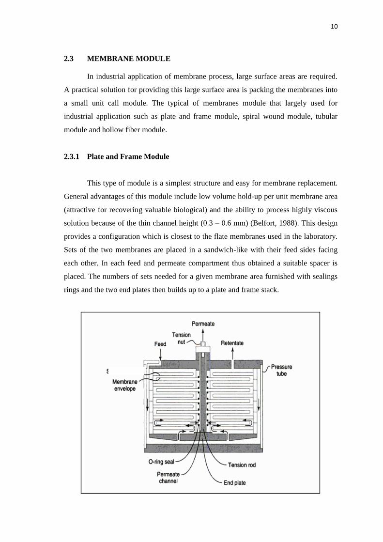
2.3.1 Plate and Frame Module
This type of module is a simplest structure and easy for membrane replacement.
General advantages of this module include low volume hold-up per unit membrane area
(attractive for recovering valuable biological) and the ability to process highly viscous
solution because of the thin channel height (0.3 – 0.6 mm) (Belfort, 1988). This design
provides a configuration which is closest to the flate membranes used in the laboratory.
Sets of the two membranes are placed in a sandwich-like with their feed sides facing
each other. In each feed and permeate compartment thus obtained a suitable spacer is
placed. The numbers of sets needed for a given membrane area furnished with sealings
rings and the two end plates then builds up to a plate and frame stack.

11
Figure 2.2: Schematic of the plate and frame module (Baker, 2000)
2.3.2 Tubular Module
In this type of module, a number of membrane of tubular shape are encased in a
container. The feed solution always flows through the center of the tubes while the
permeate flows through the porous supporting tube into the module housing. Ceramic
membranes are mostly assembled in such tubular module configurations. Tubular
module is convenience membrane replacement and easy cleaning of surface
contamination. Besides, the energy consumption is high according to per unit amount of
liquid treated.
Figure 2.3: Tubular module for ultrafiltration
Tubular module commonly used in ultrafiltration application since this module
is resistance to membrane fouling and exhibits good hydrodynamics, resulting in lower
cost of production. This module is non-self supporting membrane but it have supported
by a tube from outside. The flow in tubular membrane is inside out since the location of
tubular membrane is inside a tube. Large numbers of tubes are manifolded in series. The
feed fed through all the tubes connected in series, typically at high velocity with typical
operating pressures of 20 to 80 psi, which is sufficient to maintain turbulent flow. Clean
fluid passes through the pores membrane, while suspended particulates remain in the
retentive stream. Permeate is removed from each tube and sent to a permeate collection
header. The turbulent flow of the retentive stream prevents the cake formation on the
inner surface of the tube resulting high flux and longer shelf life (Prasad, 2010).

12
Figure 2.4: Schematic diagram of tubular module
2.3.3 Hollow Fiber Module
Hollow fiber module consists of a large number of fibers assembled together in a
module. The free ends of the fibers are often potted with agents such as epoxy resins,
polyurethanes, or silicon rubber. The membranes are self supporting for this module.
There are two basic types of arrangement for this module :
1) Inside out where the feed solution passes through the bore of the fiber and the
permeate is collected on the outside of the fiber.
2) Outside in where the feed solutions enters the module on the shell side of the
fibers and the permeate passes into the fiber bore.
The choice between the two concepts is mainly based on some parameters such as
operation pressure, pressure drop or type of membrane available. The hollow fiber
module is often used when the feed stream is relatively clean, such as in gas separation
and pervaporation. It has also been use for desalination process, but treatment is need.

13
Figure 2.5: Schematic representation of shell side feed type hollow fibre membrane
module
Figure 2.6: Schematic representation of bore side feed type of hollow fibre membrane
module
Hollow fibre membrane modules are available in two basic geometries such as
shell side feed design (figure 2.4) and bore side design (figure 2.5). In shell side
module, the system is pressurized from the shell side driving permeate through a closed
bundle of fibres contained in a pressure vessel, and permeate exits through the open
fibre ends. The shell side module is simple, easy and economic. In bore side feed type
of hollow fibre module, units are open at both ends for inlet and outlet, and the feed

14
fluid circulates through the bore of the hollow fibres. The pressure drop inside the
hollow fibers is reduced by increasing the diameter of the fine fibers and spinning
compared to the shell side feed system (Nath, 2008).
2.4 ADVANTAGES OF MEMBRANE TECHNOLOGY
There are many reasons why numerous fluid separation markets have adopted
membrane separation technologies in such a short time. But the most significant reason
is that they are more efficient than traditional technologies.
2.4.1 Energy Saving
Energy savings are among the main reasons for selecting membrane
technologies. In food processing application, the compact system of membrane can
operate at near room temperature, so at the same time, the cooling cost will be reduced.
In waste water industries, the usage of membrane will improves wastewater
management, aiding the reclamation of salable by-products from waste streams in the
food processing businesses. Besides, membrane separation has been recognizing as the
energy saving technology and high quality of production.
2.4.2 Clean Energy
The development of advanced technology in membrane separations gives
significant effect in the energy and environmental concern. The continuous use of fossil
fuels for transportation, as primary energy sources and indiscriminate use of fossil fuel
will cause considerable harm to environment. To prevent this from damage, scientists
have been actively working on upgrading membranes for fuel cells, which are expected
to compete with petroleum-based energy sources particularly in the transportation
markets. These enhanced membranes will not only improve hydrogen production for
use as a fuel in vehicles, but will also sequester carbon dioxide to reduce the greenhouse

15
effect and global warming due to burning of fossil fuels. Research in membranes for the
energy and environmental markets is particularly intense for fuel cell membranes,
hydrogen separation, and carbon dioxide recovery from fossil fuel applications.
2.4.3 The Ability of Connection to Other Processes
To meet the complex demands in fluid separation, membrane technologies can
be combined with each other and with other separation technologies. The example of
applications that is classified as the challenging application is in the treatment of
seawater and brackish water sources and wastewater recovery. Pretreatment with ultra
or micro-filtration followed by reverse osmosis is being used for desalination to
minimize fouling. In the treatment of wastewater with organic matter, membrane
bioreactors are well accepted in many parts of the world.
2.4.4 Good Weight and Space Efficiency
Skid construction can be optimized to the space available, and multiple elements
can be inserted into tubes to increase packing density. The space efficiency that is
shows in membrane technology is important especially in the limited area of plant such
as for offshore environment, where deck area is at a premium, and is the reason why so
many new offshore developments have chosen to use membranes for acid gas removal.
2.4.5 Lower Capital Cost
The scope, cost, and time taken for site preparation are minimal since membrane
systems are skid mounted, except for the larger pretreatment vessels. Therefore,
installation costs are significantly lower than alternative technologies, especially for
remote areas. Furthermore, membrane units do not require the additional facilities, such
as solvent storage and water treatment, needed by other processes.
16
2.4.6 Operational Simplicity and High Reliability
Because single-stage membrane systems have no moving parts, they have almost
no unscheduled downtime and are extremely simple to operate. They can operate
unattended for long periods, provided that external upsets, such as well shutdowns, do
not occur. Items in the pretreatment system that could cause downtime, such as filter
coalescers, are usually spared so that production can continue while the item is under
maintenance. The addition of a recycle compressor adds some complexity to the system
but still much less than with a solvent or adsorbent-based technology. Multistage
systems can be operated at full capacity as single-stage systems when the recycle
compressor is down, although hydrocarbon losses will increase. The start-up, operation,
and shutdown of a complex multistage membrane system can be automated so that all
important functions are initiated from a control room with minimal staffing (Dortmundt
and Doshi, 1999).
2.47 Lower Operating Costs
The only major operating cost for single-stage membrane systems is membrane
replacement. This cost is significantly lower than the solvent replacement and energy
costs associated with traditional technologies. The improvements in membrane and
pretreatment design allow a longer useful membrane life, which further reduces
operating costs. The energy costs of multistage systems with large recycle compressors
are usually comparable to those for traditional technologies.
2.4.8 Deferred Capital Investment
Often, contracted sales-gas flow rates increase over time, as more wells are
brought on-line. With traditional technologies, the system design needs to take this later
production into account immediately, and so the majority of the equipment is installed
before it is even needed. The modular nature of membrane systems means that only the
membranes that are needed at start-up need be installed. The rest can be added, either
into existing tubes or in new skids, only when they are required. Even on offshore