Effect of Changes in Materials and Working Fluids on the ...
9
IJSRD - International Journal for Scientific Research & Development| Vol. 7, Issue 01, 2019 | ISSN (online): 2321-0613 All rights reserved by www.ijsrd.com 638 Effect of Changes in Materials and Working Fluids on the Performance of Vortex Tubes Ravindra Shende 1 Jagdeesh Saini 2 1 M. Tech Research Scholar 2 Assistant Professor 1,2 Department of Mechanical Engineering 1,2 BM College of Technology, Indore (MP), India Abstract— Refrigerating systems has emerged as an important necessity of human life in present century. Today, these systems are used in many applications. Present research work is devoted to the investigations for of an important category of refrigerant systems, vortex tubes. In the research work, combinations of six gases and three materials are made for analyzing pressure differences and thermal gradients for a vortex tube. The flowing gases were Argon, CO2, Nitrogen, Oxygen, Helium, and air, and the materials are Cast iron, Copper and Brass. As a result, combination of Helium and Brass emerged out as the best combination for the application. Key words: Vortex Tube, Working Fluid, Materials I. INTRODUCTION Vortex tube is one of the non-conventional type refrigerating systems for the production of refrigeration. It is a simple device, which splits the pressurized gas stream into two low pressure streams (cold and hot streams). Vortex tube are known by different names, like Ranque vortex tube (on the name of inventor), and Hilsch vortex tube or Ranque-Hilsch, who enhanced the performance of these tubes after Ranque. Vortex tube is composed of nozzles’ inlet (1), a chamber for creating vortex (vortex chamber) (2), cold end orifice (3), hot tube (4), hot control valve containing hot plug (5), exit for removal of hot air (6), as shown in Figure 1.1. Fig. 1.1: A vortex tube (El-Soghiar et al., 2014) The nozzles may be of any type depending upon the specifications of tubes, like converging or diverging or converging-diverging type as per the design. Here the objective of nozzle is to offer higher velocity, greater mass flow and minimum inlet losses. Chamber contains nozzle and facilities the entry of high velocity air-stream into hot side, from tangential direction. In most of the cases, the chambers are not of circular form, and are gradually converted into spiral form. Hot side is cylindrical in cross section and is of different lengths as per the requirement of design. Valve provides the obstacle to the flow of air via hot side and it also controls the quantity of hot air through vortex tube. Diaphragm represents a cylindrical piece having a small hole at the center. Air stream traveling through the core of the hot side gets emitted with the help of a diaphragm hole. Cold side is a cylindrical portion from which cold air passes. In present research work, performance evaluation of different gases for vortex tube application is targeted by comparing pressure differences, and thermal gradients generated by them. The flowing gases are argon, CO2, nitrogen, oxygen, helium, and air, and the materials are Cast iron, Copper and Brass. For this purpose, approach of modeling and simulation of the system is carried out in ANSYS simulation software. The theoretical model used for this purpose if k-ε model. Following are the objectives of the proposed research: 1) Modeling of a vortex tube; 2) Simulation of vortex tube for different number of inlets, and 3) Identification of temperature differences, and thermal gradients for tubes for different gases and different materials. II. LITERATURE REVIEW Table 2.1 shows the research outcomes and opinions of different researchers in the field of vortex tubes. S. No Researcher(s) Contribution Kolmes et al. (2017) According to the researchers, we describe a quantitative model for heat separation in a fluid owing to motion along a pressure gradient. The physical model concerned has relevancy to one clarification for the temperature separation during a vortex tube. This impact features a point of saturation in which the fluid’s temperature and pressure are connected at its boundaries by an adiabatic law. Vortex tube models typically assume that this saturation is achieved in physical devices. We conclude that this can be seemingly to be a secure assumption abundant of the time, but we describe circumstances during which saturation may not be achieved. We tend to propose a check of our model of temperature separation. Rafiee & Sadeghiazad (2017) The air separators or vortex tubes are widely employed in rotor craft engines. The air separators are accustomed give an applicable air stream (clean air) to chopper engines. Vortex tubes are usually categorized consistent with direction of exiting flows. The research work focuses on some results (both experimental and numerical) into the improvement and analysis of the separation performance/efficiency and fluid patterns in parallel vortex tubes (PVTs) collectively of the foremost attention-grabbing kinds of air separators. concerning the Ranque–Hilsch vortex tubes,
Transcript of Effect of Changes in Materials and Working Fluids on the ...

IJSRD - International Journal for Scientific Research & Development| Vol. 7, Issue 01, 2019 | ISSN (online): 2321-0613
All rights reserved by www.ijsrd.com 638
Effect of Changes in Materials and Working Fluids on the Performance
of Vortex Tubes
Ravindra Shende1 Jagdeesh Saini2 1M. Tech Research Scholar 2Assistant Professor
1,2Department of Mechanical Engineering 1,2BM College of Technology, Indore (MP), India
Abstract— Refrigerating systems has emerged as an
important necessity of human life in present century. Today,
these systems are used in many applications. Present research
work is devoted to the investigations for of an important
category of refrigerant systems, vortex tubes. In the research
work, combinations of six gases and three materials are made
for analyzing pressure differences and thermal gradients for a
vortex tube. The flowing gases were Argon, CO2, Nitrogen,
Oxygen, Helium, and air, and the materials are Cast iron,
Copper and Brass. As a result, combination of Helium and
Brass emerged out as the best combination for the
application.
Key words: Vortex Tube, Working Fluid, Materials
I. INTRODUCTION
Vortex tube is one of the non-conventional type refrigerating
systems for the production of refrigeration. It is a simple
device, which splits the pressurized gas stream into two low
pressure streams (cold and hot streams). Vortex tube are
known by different names, like Ranque vortex tube (on the
name of inventor), and Hilsch vortex tube or Ranque-Hilsch,
who enhanced the performance of these tubes after Ranque.
Vortex tube is composed of nozzles’ inlet (1), a chamber for
creating vortex (vortex chamber) (2), cold end orifice (3), hot
tube (4), hot control valve containing hot plug (5), exit for
removal of hot air (6), as shown in Figure 1.1.
Fig. 1.1: A vortex tube (El-Soghiar et al., 2014)
The nozzles may be of any type depending upon the
specifications of tubes, like converging or diverging or
converging-diverging type as per the design. Here the
objective of nozzle is to offer higher velocity, greater mass
flow and minimum inlet losses. Chamber contains nozzle and
facilities the entry of high velocity air-stream into hot side,
from tangential direction. In most of the cases, the chambers
are not of circular form, and are gradually converted into
spiral form. Hot side is cylindrical in cross section and is of
different lengths as per the requirement of design. Valve
provides the obstacle to the flow of air via hot side and it also
controls the quantity of hot air through vortex tube.
Diaphragm represents a cylindrical piece having a small hole
at the center. Air stream traveling through the core of the hot
side gets emitted with the help of a diaphragm hole. Cold side
is a cylindrical portion from which cold air passes. In present
research work, performance evaluation of different gases for
vortex tube application is targeted by comparing pressure
differences, and thermal gradients generated by them. The
flowing gases are argon, CO2, nitrogen, oxygen, helium, and
air, and the materials are Cast iron, Copper and Brass. For this
purpose, approach of modeling and simulation of the system
is carried out in ANSYS simulation software. The theoretical
model used for this purpose if k-ε model.
Following are the objectives of the proposed research:
1) Modeling of a vortex tube;
2) Simulation of vortex tube for different number of inlets,
and
3) Identification of temperature differences, and thermal
gradients for tubes for different gases and different
materials.
II. LITERATURE REVIEW
Table 2.1 shows the research outcomes and opinions of
different researchers in the field of vortex tubes.
S.
No Researcher(s) Contribution
Kolmes et al.
(2017)
According to the researchers, we describe a quantitative model for heat separation in a fluid owing
to motion along a pressure gradient. The physical model concerned has relevancy to one
clarification for the temperature separation during a vortex tube. This impact features a point of
saturation in which the fluid’s temperature and pressure are connected at its boundaries by an
adiabatic law. Vortex tube models typically assume that this saturation is achieved in physical
devices. We conclude that this can be seemingly to be a secure assumption abundant of the time,
but we describe circumstances during which saturation may not be achieved. We tend to propose
a check of our model of temperature separation.
Rafiee &
Sadeghiazad
(2017)
The air separators or vortex tubes are widely employed in rotor craft engines. The air separators
are accustomed give an applicable air stream (clean air) to chopper engines. Vortex tubes are
usually categorized consistent with direction of exiting flows. The research work focuses on some
results (both experimental and numerical) into the improvement and analysis of the separation
performance/efficiency and fluid patterns in parallel vortex tubes (PVTs) collectively of the
foremost attention-grabbing kinds of air separators. concerning the Ranque–Hilsch vortex tubes,

Effect of Changes in Materials and Working Fluids on the Performance of Vortex Tubes
(IJSRD/Vol. 7/Issue 01/2019/167)
All rights reserved by www.ijsrd.com 639
the separated fluids (gas or liquid) or hot and cold streams (dirty and clean) leave the vortex tube
at two totally different sides, within the case of parallel vortex tubes, each exhausts are settled in
one facet (control valve position). During this analysis the results of a replacement nozzle position
(parallel injector), throttle orifice diameter (6.5–9.5mm) and length of parallel main tube (180–
220mm) on the quality of the separation method wit in the Ranque–Hilsch and also the parallel air
separator (PVT) are analyzed. The results show that the parallel vortex tube with optimized length,
injection angle and orifice diameter provides 66.08% (14.83K) and 58.61% (13.88K) higher
thermal separation performance as compared to the initial parallel vortex tube.
Attalla et al.
(2017)
The present study investigated experimentally the cooling and heating performance of two
identical counter flow vortex tubes organized in-series (VTS) and parallel (VTP). The vortex tube
used has general specifications of: aspect ratio AR = 1.6, hot tube length L = 112.5 mm, hot tube
inner diameter D = 7.5 mm, cold end diameter dc = 5 mm, and generator of 3 nozzles, N = 3. Dry
air is employed as an operating fluid with completely different inlet air pressures adjusted from 2
to 6 bars. The experimental results discovered that the utmost cold temperature distinction
occurred at the inlet gas pressure of 6 bars and cold mass fraction of 0.4 for both VTS and VTP
systems. The conducted results incontestable that the values of COPref for VTS system were over
the values of VTP system. However, the VTP yielded higher values of COPHP over the span of
investigation. The VTS system improved the COPref by twenty two.5% and 31.5% compared with
the VTP and therefore the single vortex tube system (VTO), respectively. For t e case of VTP
system, the COPHP is increased by 18.2% and 27.3% than VTS and VTO, respectively.
Cao et al. (2017)
The spatial relationship between the energy dissipation slabs and also the vortex tubes is
investigated supported the direct numerical simulation (DNS) of the channel flow. The spatial
distance between these two structures is found to be slightly larger than the vortex radius.
Comparison of the core areas of the vortex tubes and therefore the dissipation slabs offers a mean
quantitative relation of 0.16 for the mean moving strength which of 2.89 for the mean dissipation
rate. These results verify that within the channel flow the slabs of intense dissipation and therefore
the vortex tubes don't coincide in space. Rather they appear in pairs offset with a mean separation
of approximately 10 degree.
Zhang et al.
(2016)
To reveal the energy transferring mechanism in the vortex tube, which is a remarkable
development in the area of heat and mass transfer, numerical simulation and analysis of the
dynamic fluid flow were employed. In contrast to the previous static study, the main target of this
paper is the dynamic process, or the oscillation, of the secondary circulation layer. based on the
fluid flow results derived from the unsteady three-D computation, the existence of the forced or
rankine vortex was confirmed, which conjointly verified the certainty of reverse flow in the cold
end of the vortex tube. Then, the oscillation of the boundary layer of the central recirculation zone
was emphasized and the periodical vibratory of the fluid flow within the secondary circulation
zone, varying of its boundary, and therefore the typical frequencies of points on a cross section
were provided. supported these results, a unique energy transferring mechanism in the vortex tube
was planned, underneath the condition that stable oscillation of the boundary layer is the dominant
mechanism for the heat and mass transfer process.
Karthik (2015)
The vortex tube is cold equipment that produces each cold as well as hot air at both opposite ends.
The vortex tube's construction is such it is made of a hollow tube of either metallic or fibre
elements having a nozzle for letting in of compressed gas and a diaphragm or a orifice for dominant
the flow rate of air. once compressed air passes through a nozzle into the diaphragm of the vortex
tube, the air forms a spiral formed vortex, that causes the heating of air, and once this air returns
back, it cools down quickly, producing a cooling impact. The most study in the Vortex tube is that
the study of the temperature distribution of the rotating air. This impact was initially discovered
by Ranque and later by Hilsch and thus this impact is termed Ranque- Hilsch impact.
Kumar (2015)
The simultaneous unleash of hot air at one end & the cold air at the opposite end of an equivalent
tube by using compressed gas, created the pulse tube refrigeration system terribly fascinating. once
correct design and fabrication, the current vortex tube is tested within the laboratory by providing
compressed gas from a reciprocating compressor having specification of FAD=13.608 m3/hr. Co-
efficient of performance, (c.o.p.) and adiabatic efficiency, (ηadia) are achieved as 0.1075 and
10.75%.Moreover, temperature of coldest and hottest air were recorded as -6 0C and 630C
respectively.
Agrawal et al.
(2014)
An experimental investigation is administrated on Ranque–Hilsch vortex tube (RHVT). Influential
parameters such as L/D ratio, cold mass fraction, inlet pressure etc. are investigated. Further, three
completely different working media (air, nitrogen and carbon dioxide) are also tested. An in-house
facility is developed to check the vortex tubes. A value of cold mass fraction is ascertained at

Effect of Changes in Materials and Working Fluids on the Performance of Vortex Tubes
(IJSRD/Vol. 7/Issue 01/2019/167)
All rights reserved by www.ijsrd.com 640
which vortex tube performs optimally at the given pressure and L/D ratio. It is found that vortex
tube performs higher with carbon dioxide as operating fluid.
Table 2.1: Research Contributions of Different Researchers
A. Gaps in the Research
On the basis of analysis of theoretical considerations, and
research contributions made by different researchers,
following gaps in the research are being identified.
1) There is almost nil research available which compares
the performance of vortex tubes with different materials
used in the construction of vortex tubes; and
2) There is almost nil research available which suggests the
ranking of gases for vortex tubes.
III. SOLUTION METHODOLOGY
Present section tells about the details of software used in the
research work. In the present research work ANSYS R 15.0
simulation software, the details of which are presented as
follows.
A. ANSYS
ANSYS is considered as one of the renounced tools in the
field of simulation, developed by ANSYS Inc., USA. It can
be used successfully for the purpose of simulating problems
of thermal analysis, structural analysis, computational fluid
dynamics, harmonic analysis, modal analysis, transient
dynamics, buckling, and other categories. In addition to this,
software also offers the facility to develop simple models.
With the help of inbuilt library, one can find out the properties
of materials, and even add the desired properties or new
materials with the known values of properties. ANSYS also
include a set of models to solve complex problems of
engineering, architecture, physical sciences, mathematical
models and other applications.
IV. CASE STUDY
Present section is devoted to the details of solution
methodology adapted to for solving the research problem, and
explains in details about problem formulation, development
of vortex tube model, and different properties used for
simulation of model with the applications of constrains.
A. Model Formulation
First step in the research work was the formulation of model
of vortex tube. For this purpose dimensions of a standard
vortex tube are used. The adopted vortex tube is called
Ranque-Hilsch vortex tube, the details of which are presented
in Figure 4.1.
Fig. 4.1: Dimensions of Conventional Vortex Tube (El-
Soghiar et al., 2014)
Figure 4.2 shows the details of arrangements of nozzles of
above mentioned vortex tube.
Fig. 4.2: Nozzle arrangements for Conventional Vortex
Tube (El-Soghiar et al., 2014)
Following are the details of specifications of above
mentioned vortex tube.
S.
No Dimension Value Material
Inlet nozzle Brass (No. off 4), 2 x 2
mms
Hot tube
Brass,
Copper and
Cast Iron
diameter = 11
mm and length =
143 mm
Cold orifice
Brass,
Copper and
Cast Iron
5.5 mm
Hot plug
Brass,
Copper and
Cast Iron 60⁰
Modified
vortex
chamber
Brass
D = 12, 16, 20
mms, and L = 10,
15, 20 mm
Table 4.1: Specifications of Vortex Tube (El-Soghiar et al.,
2014)
In present research work, effect of nozzle openings
on the performance of conventional vortex tube is
investigated. For this purpose, first of all a model of vortex
tube was developed in modeling software using above
mentioned details, and then imported in a well-known
simulation software ANSYS 15.0 Following are the details of
model.
Fig. 4.3: Model of Vortex Tube
B. Solution of the Model
After formulation of model, its solution was derived. For this
purpose, first of all meshing of the model was carried out.

Effect of Changes in Materials and Working Fluids on the Performance of Vortex Tubes
(IJSRD/Vol. 7/Issue 01/2019/167)
All rights reserved by www.ijsrd.com 641
With the help of meshing, a body can be made deformable
due to which, it can show changes in its properties,
dimensions, stress levels, etc. The chosen elements for
meshing were tetrahedron elements. Selection of mesh size
was software based. Figure 4.4 shows the mesh diagram for
the vortex tube.
Fig. 4.4: Mesh structure of Vortex Tube
In next step inlet and outlet domains were decided
as mentioned in Figure 4.5, given below.
Fig. 4.5: Inlet and Outlet Domain Finalization for the Vortex
Tube
Following are the details of parameters used for
investigations, chosen with the help of expert opinion.
S. No Parameter Value
Inlet pressure 5 bar
Inlet temperature 303 K
Outlet Pressure (hot end) 1 bar
Outlet Pressure (cold end) bar
Table 4.2: Parameters used in finding different thermal
properties from Vortex Tube
V. RESULTS AND DISCUSSION
Present chapter is devoted to results and discussions about the
research work. In present research work, on applying
different gases, values of pressures and temperature gradients
are investigated. The details of the results obtained, and
discussion made on the basis of yielded results are presented
in succeeding chapters.
A. Results
Following are the results obtained from calculations for
pressures of different gases used in vortex tubes with different
materials.
(a) Argon
(b) Carbon dioxide
(c) Nitrogen
(d) Oxygen
(e) Helium
(f) Air
Fig. 5.1: Values of pressures for different gases with CI tube
(a) Argon
(b) Carbon dioxide

Effect of Changes in Materials and Working Fluids on the Performance of Vortex Tubes
(IJSRD/Vol. 7/Issue 01/2019/167)
All rights reserved by www.ijsrd.com 642
(c) Nitrogen
(d) Oxygen
(e) Helium
(f) Air
Fig. 5.2: Values of pressures for different gases with Cu
tube
(a) Argon
(b) Carbon dioxide
(c) Nitrogen
(d) Oxygen
(e) Helium
(f) Air
Fig. 5.3: Values of pressures for different gases with Brass
tube
Following are the results obtained from calculations
for thermal gradients of different gases used in vortex tubes
with different materials.
(a) Argon
(b) Carbon dioxide
(c) Nitrogen

Effect of Changes in Materials and Working Fluids on the Performance of Vortex Tubes
(IJSRD/Vol. 7/Issue 01/2019/167)
All rights reserved by www.ijsrd.com 643
(d) Oxygen
(e) Helium
(f) Air
Fig. 5.4: Values of thermal gradients for different gases with
CI tube
(a) Argon
(b) Carbon dioxide
(c) Nitrogen
(d) Oxygen
(e) Helium
(f) Air
Fig. 5.5: Values of thermal gradients for different gases with
Cu tube
(a) Argon
(b) Carbon dioxide
(c) Nitrogen
Effect of Changes in Materials and Working Fluids on the Performance of Vortex Tubes
(IJSRD/Vol. 7/Issue 01/2019/167)
All rights reserved by www.ijsrd.com 644
(d) Oxygen
(e) Helium
(f) Air
Fig. 5.6: Values of thermal gradients for different gases with
Brass tube
B. Discussion
From the results obtained, it can be found that there are three
criteria on which rankings of the alternatives can be made;
pressure difference, and temperature gradient. Reason behind
choosing pressure difference as a criterion is that more is the
pressure difference, more will be the temperature difference
obtained. The last criteria are temperature gradient which
represents the change in temperature with respect to the
change in length of the vortex tube. Table 5.1 shows the
summarized results of the analysis.
S.No
Mat
eria
l
Gas
Pre
ssu
re M
ax
Pressure Min
Pre
ssu
re D
iffe
ren
ce
Ran
k
Tem
per
atu
re
Gra
die
nt
Ran
k
1
Cas
t Ir
on
Argon 5.37E-001 2.390E-001 2.98E-01 18 2.908E-001 18
2 Carbon di Oxide 5.554E-001 1.032E-001 4.52E-01 16 2.949E-001 17
3 Nitrogen 5.538E-001 1.049E-001 4.49E-01 17 3.013E-001 16
4 Oxygen 5.935E-001 1.070E-001 4.87E-01 11 3.143E-001 15
5 Helium 5.874E-001 1.166E-001 4.71E-01 13 3.216E-001 14
6 Air 5.985E-001 1.258-001 4.73E-01 12 3.288E-001 13
7
Co
pp
er
Argon 5.735E-001 1.198E-001 4.54E-01 15 3.290E-001 12
8 Carbon di Oxide 5.837E-001 1.288E-001 4.55E-01 14 3.378E-001 11
9 Nitrogen 6.589E-001 1.396E-001 5.19E-01 8 3.418E-001 10
10 Oxygen 6.936E-001 1.420E-001 5.52E-01 1 3.558E-001 8
11 Helium 6.828E-001 1.372E-001 5.46E-01 2 3.498E-001 9
12 Air 6.725E-001 1.328E-001 5.40E-01 4 3.596E-001 7
13
Bra
ss
Argon 6.805E-001 1.493E-001 5.31E-01 6 3.727E-001 6
14 Carbon di Oxide 6.851E-001 1.538E-001 5.31E-01 5 3.781E-001 5
15 Nitrogen 7.128E-001 1.958E-001 5.17E-01 9 4.085E-001 4
16 Oxygen 7.569E-001 2.126E-001 5.44E-01 3 4.187E-001 3
17 Helium 7.585E-001 2.284E-001 5.30E-01 7 4.282E-001 1
18 Air 7.482E-001 2.358E-001 5.12E-01 10 4.221E-001 2
Table 5.1: Summarized results of analysis
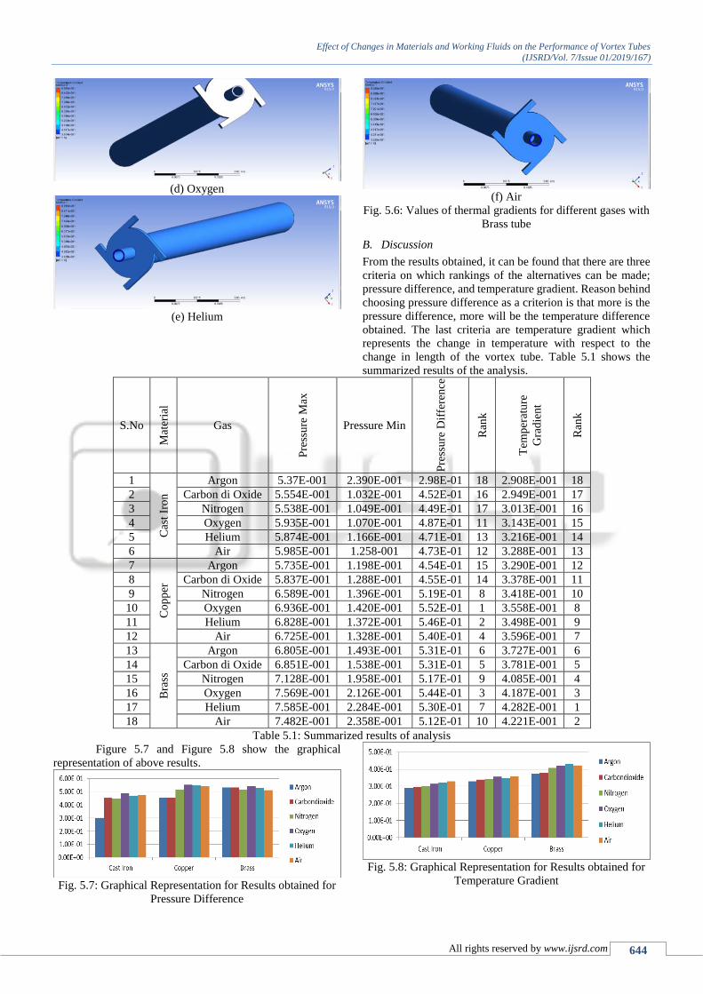
Figure 5.7 and Figure 5.8 show the graphical
representation of above results.
Fig. 5.7: Graphical Representation for Results obtained for
Pressure Difference
Fig. 5.8: Graphical Representation for Results obtained for
Temperature Gradient

Effect of Changes in Materials and Working Fluids on the Performance of Vortex Tubes
(IJSRD/Vol. 7/Issue 01/2019/167)
All rights reserved by www.ijsrd.com 645
From above mentioned results it can be analyzed
that the brass can be treated as the best material out of three
available alternatives, as it shows the best performance on the
criteria, pressure difference and thermal gradient. On the
other hand, cast iron, in spite of having a good density, has
scored rank three. The reason behind this behavior may be
the roughness of the material, due to which energy might be
lost in overcoming friction.
From Figure 5.7, it can be found out that there is a
considerable difference in the scores for pressure differences
for different gases in three materials. For cast iron and
Copper, Oxygen scores rank one while Argon scores rank six,
but for Brass, Oxygen ranks one but air ranks six.
Considering these results one can say that oxygen should be
chosen on pressure difference criteria.
But due to explosive nature of the gas, it cannot be
recommended, in spit, other option can be proposed. In the
Figure 5.7, it can be found that Helium scores rank two for
both Brass and Copper. Helium is the first noble gas in the
periodic table. Considering the properties of the gas, it can be
proposed as the best option for the operation in vortex tube.
After Helium, air scores the ranking second for the materials
Brass and Copper. After air Nitrogen can be considered as the
third option for the materials.
From Figure5.8, it can be found that Helium for
Brass, and air for Copper and Cast iron scores rank one. For
rank two, air for Brass, Oxygen for Copper, and Helium for
Cast iron appear as suitable alternatives. For rank three,
Oxygen appears as an option for all the three materials. For
rank four, Nitrogen appears as the suitable option. In all the
cases Argon scores rank six.
Considering these diverged results, it can be found
that unique ranking from both the criteria is not possible.
Therefore, following pattern of rankings is proposed
S.No
Criteria
Rank Pressure
Difference
Thermal
Gradient Remarks
I Brass-
Helium
Brass-
Helium
Oxygen is not
recommended
for rank one
II Brass-Air Brass-
Air
III Brass-
Nitrogen
Brass-
Nitrogen
Oxygen is not
recommended
for rank three
Table 5.2: Overall rankings of Materials and Gases
VI. CONCLUSION, LIMITATIONS AND FUTURE SCOPE OF THE
RESEARCH
In this section, details of conclusion, limitations and future
scope of the research are presented.
A. Conclusion
Present research work is focused on the thermal analysis of a
vortex tube for performance enhancement. For this purpose a
standard vortex tube was selected and thermal analysis on it
was performed using six different gases, including the air.
The gases selected for the purpose of analysis were argon,
carbon dioxide, nitrogen, oxygen, helium and air. In the
analysis, three materials, Cast iron, Copper and Brass were
also used. Thermal analysis of radiator model was done on
very popular analysis software ANSYS 15.0, under which
maximum pressure, minimum pressure for the calculation of
pressure difference and thermal gradient were investigated.
Following points represent the conclusion of the research
work.
1) Conclusion for Materials:
1) Brass shows the best performance out of all available
options and ranks one;
2) Copper scores rank two; and
3) Cast iron scores rank three.
2) Conclusion for Working Fluids:
1) For both the criteria, helium ranks one;
2) For both the criteria, air scores rank two; and
3) For both the criteria, Nitrogen scores ranks three.
B. Limitations and Future Scope of the Research
Following are the limitations of research work.
The research work is limited to investigations to vortex
refrigeration system only;
The research work is also limited to investigations
about limited properties of the gases; and
The research work is also limited to performance
evaluation of a small set of properties.
Following points indicate the future scope of research work.
On the criteria of pressure difference, Oxygen showed
the best performance however it was recommended. A
research considering Oxygen blended with some inert
gases may be initiated;
A research work considering a broader set of
refrigeration systems may be initiated;
A research work can also be initiated which shall
consists of a broader set of thermal properties of gases;
and
A research work considering broader sets of properties
can also be undertaken.
REFERENCES
[1] Agrawal, N., Naik, S. S., & Gawale, Y. P. (2014).
Experimental investigation of vortex tube using natural
substances. International Communications in Heat and
Mass Transfer, 52, 51-55.
[2] Attalla, M., Ahmed, H., Ahmed, M. S., & El-Wafa, A.
A. (2017). An experimental study of nozzle number on
Ranque Hilsch counter-flow vortex tube. Experimental
Thermal and Fluid Science, 82, 381-389.
[3] Cao, L. K., Li, D. X., Chen, H., & Liu, C. J. (2017).
Spatial relationship between energy dissipation and
vortex tubes in channel flow. Journal of Hydrodynamics,
Ser. B, 29(4), 575-585.
[4] Karthik, S. (2015). An Experimental Setup of Vortex
Tube Refrigeration System. International Journal of
Engineering Research & Technology (IJERT) ISSN,
2278-0181.
[5] Kolmes, E. J., Geyko, V. I., & Fisch, N. J. (2017). Heat
pump model for Ranque–Hilsch vortex tubes.
International Journal of Heat and Mass Transfer, 107,
771-777.

Effect of Changes in Materials and Working Fluids on the Performance of Vortex Tubes
(IJSRD/Vol. 7/Issue 01/2019/167)
All rights reserved by www.ijsrd.com 646
[6] Kumar Ashok (2015). Experimental Investigation and
Performance of Vortex Tube Refrigeration. International
Journal of Science and Research, 5 (12), 780 – 784.
[7] Rafiee, S. E., & Sadeghiazad, M. M. (2017). Efficiency
evaluation of vortex tube cyclone separator. Applied
Thermal Engineering, 114, 300-327.
[8] Zhang, B., Guo, X., & Yang, Z. (2016). Analysis on the
fluid flow in vortex tube with vortex periodical
oscillation characteristics. International Journal of Heat
and Mass Transfer, 103, 1166-1175.