Efficient and Reliable Sensor Models for Humanoid Soccer ... · Efficient and Reliable Sensor...
8
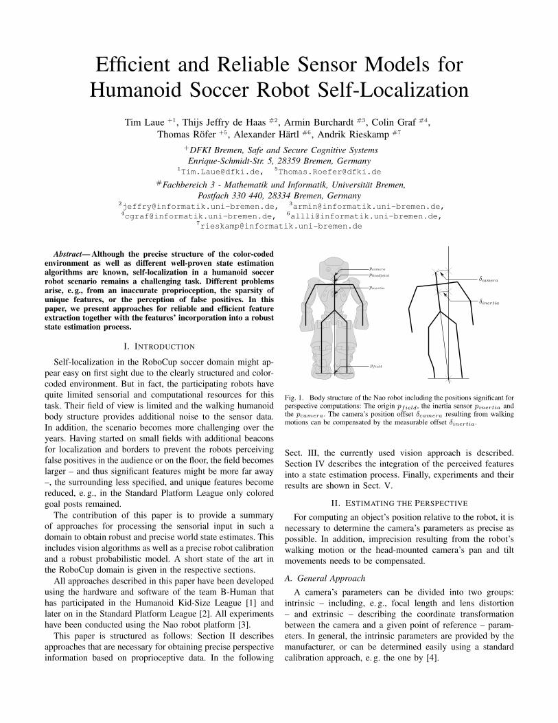
Efficient and Reliable Sensor Models for Humanoid Soccer Robot Self-Localization Tim Laue +1 , Thijs Jeffry de Haas #2 , Armin Burchardt #3 , Colin Graf #4 , Thomas R¨ ofer +5 , Alexander H¨ artl #6 , Andrik Rieskamp #7 + DFKI Bremen, Safe and Secure Cognitive Systems Enrique-Schmidt-Str. 5, 28359 Bremen, Germany 1 [email protected], 5 [email protected] # Fachbereich 3 - Mathematik und Informatik, Universit¨ at Bremen, Postfach 330 440, 28334 Bremen, Germany 2 [email protected], 3 [email protected], 4 [email protected], 6 [email protected], 7 [email protected] Abstract— Although the precise structure of the color-coded environment as well as different well-proven state estimation algorithms are known, self-localization in a humanoid soccer robot scenario remains a challenging task. Different problems arise, e. g., from an inaccurate proprioception, the sparsity of unique features, or the perception of false positives. In this paper, we present approaches for reliable and efficient feature extraction together with the features’ incorporation into a robust state estimation process. I. I NTRODUCTION Self-localization in the RoboCup soccer domain might ap- pear easy on first sight due to the clearly structured and color- coded environment. But in fact, the participating robots have quite limited sensorial and computational resources for this task. Their field of view is limited and the walking humanoid body structure provides additional noise to the sensor data. In addition, the scenario becomes more challenging over the years. Having started on small fields with additional beacons for localization and borders to prevent the robots perceiving false positives in the audience or on the floor, the field becomes larger – and thus significant features might be more far away –, the surrounding less specified, and unique features become reduced, e. g., in the Standard Platform League only colored goal posts remained. The contribution of this paper is to provide a summary of approaches for processing the sensorial input in such a domain to obtain robust and precise world state estimates. This includes vision algorithms as well as a precise robot calibration and a robust probabilistic model. A short state of the art in the RoboCup domain is given in the respective sections. All approaches described in this paper have been developed using the hardware and software of the team B-Human that has participated in the Humanoid Kid-Size League [1] and later on in the Standard Platform League [2]. All experiments have been conducted using the Nao robot platform [3]. This paper is structured as follows: Section II describes approaches that are necessary for obtaining precise perspective information based on proprioceptive data. In the following Fig. 1. Body structure of the Nao robot including the positions significant for perspective computations: The origin p f ield , the inertia sensor p inertia and the pcamera. The camera’s position offset δcamera resulting from walking motions can be compensated by the measurable offset δ inertia . Sect. III, the currently used vision approach is described. Section IV describes the integration of the perceived features into a state estimation process. Finally, experiments and their results are shown in Sect. V. II. ESTIMATING THE PERSPECTIVE For computing an object’s position relative to the robot, it is necessary to determine the camera’s parameters as precise as possible. In addition, imprecision resulting from the robot’s walking motion or the head-mounted camera’s pan and tilt movements needs to be compensated. A. General Approach A camera’s parameters can be divided into two groups: intrinsic – including, e. g., focal length and lens distortion – and extrinsic – describing the coordinate transformation between the camera and a given point of reference – param- eters. In general, the intrinsic parameters are provided by the manufacturer, or can be determined easily using a standard calibration approach, e. g. the one by [4].
Transcript of Efficient and Reliable Sensor Models for Humanoid Soccer ... · Efficient and Reliable Sensor...
Efficient and Reliable Sensor Models forHumanoid Soccer Robot Self-Localization
Tim Laue +1, Thijs Jeffry de Haas #2, Armin Burchardt #3, Colin Graf #4,Thomas Rofer +5, Alexander Hartl #6, Andrik Rieskamp #7
+DFKI Bremen, Safe and Secure Cognitive SystemsEnrique-Schmidt-Str. 5, 28359 Bremen, Germany
[email protected], [email protected]#Fachbereich 3 - Mathematik und Informatik, Universitat Bremen,
Postfach 330 440, 28334 Bremen, [email protected], [email protected],[email protected], [email protected],
Abstract— Although the precise structure of the color-codedenvironment as well as different well-proven state estimationalgorithms are known, self-localization in a humanoid soccerrobot scenario remains a challenging task. Different problemsarise, e. g., from an inaccurate proprioception, the sparsity ofunique features, or the perception of false positives. In thispaper, we present approaches for reliable and efficient featureextraction together with the features’ incorporation into a robuststate estimation process.
I. INTRODUCTION
Self-localization in the RoboCup soccer domain might ap-pear easy on first sight due to the clearly structured and color-coded environment. But in fact, the participating robots havequite limited sensorial and computational resources for thistask. Their field of view is limited and the walking humanoidbody structure provides additional noise to the sensor data.In addition, the scenario becomes more challenging over theyears. Having started on small fields with additional beaconsfor localization and borders to prevent the robots perceivingfalse positives in the audience or on the floor, the field becomeslarger – and thus significant features might be more far away–, the surrounding less specified, and unique features becomereduced, e. g., in the Standard Platform League only coloredgoal posts remained.
The contribution of this paper is to provide a summaryof approaches for processing the sensorial input in such adomain to obtain robust and precise world state estimates. Thisincludes vision algorithms as well as a precise robot calibrationand a robust probabilistic model. A short state of the art inthe RoboCup domain is given in the respective sections.
All approaches described in this paper have been developedusing the hardware and software of the team B-Human thathas participated in the Humanoid Kid-Size League [1] andlater on in the Standard Platform League [2]. All experimentshave been conducted using the Nao robot platform [3].
This paper is structured as follows: Section II describesapproaches that are necessary for obtaining precise perspectiveinformation based on proprioceptive data. In the following
Fig. 1. Body structure of the Nao robot including the positions significant forperspective computations: The origin pfield, the inertia sensor pinertia andthe pcamera. The camera’s position offset δcamera resulting from walkingmotions can be compensated by the measurable offset δinertia.
Sect. III, the currently used vision approach is described.Section IV describes the integration of the perceived featuresinto a state estimation process. Finally, experiments and theirresults are shown in Sect. V.
II. ESTIMATING THE PERSPECTIVE
For computing an object’s position relative to the robot, it isnecessary to determine the camera’s parameters as precise aspossible. In addition, imprecision resulting from the robot’swalking motion or the head-mounted camera’s pan and tiltmovements needs to be compensated.
A. General Approach
A camera’s parameters can be divided into two groups:intrinsic – including, e. g., focal length and lens distortion– and extrinsic – describing the coordinate transformationbetween the camera and a given point of reference – param-eters. In general, the intrinsic parameters are provided by themanufacturer, or can be determined easily using a standardcalibration approach, e. g. the one by [4].

Fig. 2. Projection of the field geometry into the camera image before (left)and after (right) calibrating the additional camera parameters.
Most calibration approaches also allow determining ex-trinsic parameters, but since a soccer robot’s camera is inconstant motion, a different solution is necessary. A reasonableapproach is to define an origin of the robot relative worldcoordinate system – in our case the center between the twofeet, depicted as pfield in Fig. 1 – and to follow the robot’skinematic chain from this point to the camera.
B. Additional Camera Calibration
In addition to the previously described parameters, some ad-ditional robot-specific parameters are required two overcometwo problems: the camera cannot be mounted perfectly plain –this is especially the cases for self-assembled robots but alsofor the commercially manufactured Nao – and the torso isnot always standing perfectly vertical due to backlash whichcannot be measured. In both cases, small variations can leadto significant errors when projecting more distant objects ontothe field, as shown in Fig. 2.
These parameters, correcting the camera roll and tilt as wellas the overall body roll and tilt, are currently determined in amanual calibration process.
C. Filtering and Integrating Inertia Data
During walking, a computation of the extrinsic camera pa-rameters is still possible but subject to heavy noise. The sensordata provided by the motors does not reflect the swinging ofthe robot’s body during certain walk phases. Therefore, theresulting camera offset δcamera needs to be compensated (cf.Fig. 1). This is realized by estimating the torso’s offset δinertiabased on the measurements of the inertia sensor in the Nao’schest.
Estimating the pose of the torso consists of three differenttasks. First, discontinuities in the inertial sensor readings areexcluded. Second, the calibration offsets for the two gyro-scopes are maintained. Third, the actual torso pose is estimatedusing an Unscented Kalman filter (UKF) [5].
Excluding discontinuities in the sensor readings is neces-sary, because some sensor measurements provided by the Naocannot be explained by the usual sensor noise. This mal-function occurs sporadically and affects most measurementsfrom the inertia board within a single frame (cf. Fig. 3). Thecorrupted frames are detected by comparing the difference ofeach value and its predecessor to a predefined threshold.
Gyroscopes have a bias drift, i. e., the output when theangular velocity is zero drifts over time due to factors such as
Fig. 3. The difference between the estimated pitch angle angleY and thepitch angle rawAngleY provided by the inertia board of the Nao. Between theframes 85 and 80, the Nao provided corrupted sensor values.
temperature that cannot be observed. The temperature changesslowly as long as the robot runs, so that it is necessary toredetermine the bias continuously. Therefore, it is hypoth-esized that the torso of the robot and thereby the inertialmeasurement unit has the same pose at the beginning andthe end of a walking phase (i. e. two steps). Therefore, theaverage gyro measurement over a whole walking should bezero. This should also apply if the robot is standing. So either,the average measurements over a whole walking phase aredetermined, or the average over 1 sec for a standing robot.These averages are filtered through one-dimensional Kalmanfilters and used as biases of the gyroscopes. The collection ofgyroscope measurements is limited to situations in which therobot is either standing or walking slowly and has contact tothe ground (determined through the force sensitive resistors inthe Nao’s feet).
The UKF estimates the pose of the robot torso (cf. Fig. 3)that is represented as three-dimensional rotation matrix. Thechange of the rotation of the feet relative to the torso in eachframe is used as process update. The sensor update is derivedfrom the calibrated gyroscope values. Another sensor update isadded from a simple absolute measurement realized under theassumption that the longer leg of the robot rests evenly on theground as long as the robot stands almost upright. In cases inwhich this assumption is apparently incorrect, the accelerationsensor is used instead.
It is not only possible to get the orientation from theUKF, but also to get a “filtered” version of the gyroscopemeasurements from the change in orientation, including acalculated z-gyroscope value that is actually missing on theNao.
D. Compensating Image Distortion
The Nao robot – as well as most humanoid soccer robots –is equipped with a simple CMOS camera. Such cameras have

Fig. 4. The field border: the thin dashed red line depicts the robot’s horizon,the blue line connects the green points found, and the red dotted line is theupper part of the convex hull around the field.
a central weakness, the so-called rolling shutter. Instead oftaking images at a certain point in time, a rolling shutter takesan image pixel by pixel, row by row. Thus the last pixel of animage is taken significantly later than the first one. By movingits head, the Nao can point the camera in different directions.Since an image is not taken all at once, the camera may pointto a different direction when the first pixel is recorded thanwhen the last pixel is taken. This results in a distorted imageand thus in inaccurate perceptions.
To overcome this problem, a mechanism – originally de-veloped for the AIBO robot – based on the image recordingtime and the speed of the head joints is applied. For a detaileddescription see [6].
III. FEATURE EXTRACTION
The most time-consuming and often also most error-pronesoftware component of a soccer robot is its vision system. Byintegrating knowledge about the spatial context, our approachprovides robust results without being too computationallyexpensive.
A. General Approach
For computer vision in this domain, two main approachesare popular: blob-based and grid-based systems. For extractingblobs from an image, full color segmentation is necessary.After the segmentation, connected regions of the same colorclass become determined. A common solution for this task isCMVision by [7]. This approach provides robust results butis quite time-consuming (on robots such as the Nao) sinceevery pixel of the image needs to be examined. Grid-basedapproaches can be significantly faster, since only a fractionof all pixels becomes interpreted namely those on a (oftenhorizon-aligned) grid. This technique was introduced in theStandard Platform League by [8]. Since the grid lines areonly one-dimensional, only a small context of a pixel can beconsidered and thus makes this approach more sensitive to
Fig. 5. Body contour in 3-D (left) and projected to the camera image afterkicking the ball (right).
outliers. To overcome this problem, often so-called specialistsneed to be applied, examining a feature’s region in more detail.
Our approach is a combination of both techniques: In a firststep, significant segments are searched on a grid. This grid isbounded by the robot’s spatial context, i. e. the border of thefield and its own body contour (cf. Sect. III-B). In a secondstep, the segments become merged to regions according toa set of constraints. These regions are the base for the finalfeature detection.
B. Context of Field and Body
Since the robot soccer environment is flat and all featuresthat need to be detected (ball, field lines, and goal post) havetheir base on the ground, the segmentation only needs tobe done for the part of the image that is below the visiblefield border. The field border itself is also on the ground andtherefore must be below the horizon in the image that serves asa starting point for detecting the field border. This is done byrunning scan lines, starting from the horizon, downwards untila green segment of a minimum length is found. From thesepoints the upper half of the convex hull is used as field border.Figure 4 depicts the necessary elements for this computation.
If the robot sees parts of its own body, it might confusewhite areas with field lines and – under certain conditions – redparts with the ball. However, by using forward kinematics, therobot can actually know where its body is visible in the cameraimage and exclude these areas from image processing. This isachieved by modeling the boundaries of body parts that arepotentially visible in 3-D (cf. Fig. 5 left) and projecting themback to the camera image (cf. Fig. 5 right). The part of thatprojection that intersects with the camera image or is above itis used by the image processor as lower clipping boundary. Theprojection relies on the image coordinate system (cf. Sect. II-D), i. e., the linear interpolation of the joint angles to match thetime when the image was taken. However if joints accelerateor decelerate, the projection may not be accurate, as can beseen in Fig. 5 right), where the foot just stopped after a kick.In that case, the clipping region might be too big or too small.
C. Segmentation and Region-Building
After all boundaries have been computed, scan lines withinthe remaining valid area can be used to create segments. Forthe goal detection two special scans are done to detect verticaland horizontal yellow or blue segments above the horizon.

Fig. 6. Segmentation and region-building: The left image depicts thesegments found on scan lines and the finally computed lines (accepted redlines and one orange line segment that is too short for later consideration).The right image shows the regions that result from merging single segments.Some failed constraints are denoted with numbers: (1) not connected becauseof change in direction, (2) not connected because of the length ratio, (3)maximum size reached
The horizontal scan lines are continued below the horizonuntil there is a scan line in which no yellow or blue segmentis found. Based on these segments, regions are created byuniting touching segments of the same color to a region. Whitesegments (being candidates for field lines) touching each otherneed to fulfill certain constraints to become united to a region:
• There is a maximum region size• The length ratio of the two touching segments may not
exceed a certain maximum• The change in direction may not exceed a certain maxi-
mum (the vector connecting the middle of the segmentsconnected to the middle of the next segment is treated asdirection)
• If two segments are touching each other and both alreadyare connected to a region, they are not united
These restrictions are needed because we do not want to havea single big region containing all field lines and robots. Theresult of these restrictions is that we most likely get smallstraight white regions (cf. Fig. 6).
This process is not applied to potential goal segments. Theirmerging is described in cf. Sect. III-E.
The following region classification is done by iterating overall regions and filtering all white regions to determine whetherthe region could be a part of a line. Thus, a white region needsto fulfill the following constraints:
• It has to have a certain minimum size.• The axis of orientation must be determinable (since this
is the base information passed to further modules).• The amount of neighboring uncolored regions must be
very small (since robot parts are classified as uncolored).• It has to have a certain amount of green around.
D. Detecting Lines
For each white region that was classified as line region thestart and end point of the axis of orientation is transformedto field coordinates. These two points form a line segment.The lines are built by clustering the associated segments, asshown in algorithm 1. The basic idea of the algorithm is similarto the quality threshold clustering algorithm introduced by[9], but it ensures that it runs in the worst-case-scenario in
O(n2) runtime. Therefore, it is not guaranteed to find optimalclusters. Since the number of line segments is limited by thefield setup, practical usage showed that the algorithm has anacceptable runtime and delivers satisfiable results.
Algorithm 1 Clustering LineSegmentswhile lineSegments 6= ∅ do
s← lineSegments.pop()supporters← ∅for all s′ ∈ lineSegments do
if similarity(s, s′) < similarityThreshold thensupporters.add(s′)
end ifend forif supporters.size() > supporterThreshold then
createLine({s} ∪ supporters)lineSegments← lineSegments\supporters
end ifend while
All remaining line segments are taken into account forthe circle detection. For each pair of neighboring segmentsthe intersection of the perpendicular from the middle of thesegments is calculated. If the distance of this intersection isclose to the real circle radius, for each segment a spot isgenerated which has the distance of the radius to the segment.Now the same clustering algorithm used for the lines is usedto find a cluster for the circle. For all line segments that wereneither clustered to a line nor to the circle and have a certainminimum size, additional lines are created. This is necessarybecause a vertical line might create one big single region. Forall lines the intersections are calculated and classified as L, T,or X intersection.
E. Detecting GoalsTo detect goal posts, a Hough Transformation on the hori-
zontal goal segments is performed to search for long verticalblue or yellow lines. The lines found are then checked whetherthey match some characteristic properties of a goal post, tomake sure not to accept blue robot parts or things outside thefield as goal posts. The most important checks are:
• Is there some green below the post?• Is the bottom of the percept under the calculated horizon
and the top above it?• Does the expected width of the goal post match the width
of the percept?• Is the calculated distance of the goal post within a
plausible range?• Do we see goal posts of only one color?Percepts that do not fulfill these criteria are completely
discarded since for the state estimation process avoiding falsepositives is more important than integrating new information.For the remaining percepts, a determination of the side isperformed. If there are exactly two remaining percepts of thesame color, this can be done easily. Otherwise, the surroundingof the head point of the only remaining percept is scanned inorder to try to detect parts of the crossbar and to determinethe side of the post.

Fig. 7. Two-dimensional example of a robot observing the base point of agoal post. The distance d can be computed given the intrinsic (contributingto α) and extrinsic (providing h, contributing to α) camera parameters.
IV. SELF-LOCALIZATION
Subsequent to the feature extraction, the self-localizationintegrates the perceptions into the robot pose estimate. Formodeling the uncertainties in the probabilistic approach ap-plied, especially the remaining errors of the perspective esti-mation and the shortcomings of the vision system need to betaken into account. In addition, the constraints resulting fromthe computational limits demand a careful parameterization.
A. General Approach
For self-localization, we use a particle filter based on theMonte Carlo method [10] as it is a proven approach to provideaccurate results in such an environment [11]. Additionally, itis able to deal with the kidnapped robot problem that oftenoccurs in RoboCup scenarios. For a faster reestablishmentof a reasonable position estimate after a kidnapping, theAugmented MCL approach by [12] has been implemented.A comprehensive description of our general state estimationimplementation – applied to a Humanoid League scenario – isgiven in [13], in the meantime extended by a new clusteringapproach for pose extraction [14].
An alternative standard approach for robot self-localizationwould be the application of a Kalman filter, but the majordrawback of this kind of technique is its missing abilityof recovering from a kidnapping situation. However, recentresults from [15] indicate the usage of Multiple Model Kalmanfilters as a reasonable alternative to a particle filter. Thetechniques described in the following sections might also beapplicable with reservations to that approach.
In the following, the state Xt to be estimated and thus thecontent of every particle x[m]
t within a set of M particles (M =100) is a simple pose in 2-D:
x[m]t := 〈px[m]
t , py[m]t , θ
[m]t 〉 (1)
A sample’s weighting is denoted by w[m]t .
B. Modeling Uncertainty
When performing the Monte Carlo sensor update step, eachsample’s weighting w
[m]t becomes computed based on the
deviation of the model x[m]t from the current perceptions.
Let p1, . . . , pn be the perceptions made within one executioncycle and w(x, p) a function computing the likelihood ofan observation given a sample’s state, a weighting can becomputed as follows:
w[m]t = w(x[m]
t , p1)w(x[m]t , p2) . . . w(x[m]
t , pn) (2)
To determine w(x[m]t , p) for a perception p, two deviations
from the expected model need to be taken into account:the deviation of the direction on the ground as well asthe difference of the distances. The crucial aspect of thelikelihood computation is its coordinate system. A visionsystem might provide the perception as a vectorial offset or inpolar coordinates, but in both systems the distance uncertaintyresulting from the humanoid robot’s body shaking can onlybe modeled insufficiently. As depicted in Fig. 7, the distancedepends on the angle α relative to the robot’s camera position.During walking, α is subject to noise and small deviations canobviously cause huge distance errors for far perceptions. Sinceclose perceptions are not affected by this problem and similarproblems occur for directional deviations in the ground plane,it is a reasonable choice to compute w(x[m]
t , p) in angularcoordinates.
Given the angle αp determining the distance to a perception(as depicted in Fig. 7), the angle βp determining the directionaldeviation on the ground, the accordant model angles α
x[m]t
andβx[m]t
, and the percept type-related standard deviations σαpand
σβp, w[m]
t can be computed as follows:
δ[m]α = |αp − αx[m]
t| (3)
δ[m]β = |βp − βx[m]
t| (4)
w[m]t = N (δ[m]
α , σ2αp
)N (dist[m]t , σ2
βp) (5)
To save computation time, the current implementation doesnot use all perceptions of an execution cycle but selects nrandom perceptions to become integrated (currently, n = 6);goalposts are preferred since they are the only unique elementsproviding a global direction.
C. Preventing Particle Depletion
Since the computational resources are limited, a particlefilter can only be operating on a small particle set to remainefficient. Our implementation is currently configured to useonly 100 samples. But even when using e. g. 500 samples,only a sparse coverage of the state space can be realized. Thus,the problem of particle depletion might occur, i. e. during theMCL resampling step the probability distribution reduces to asmall set of particles. Especially in this scenario, having robotswith a strongly limited field of view, it might happen thatcertain local observations – not necessarily being exceedinglycompatible to the global hypothesis – fit perfectly a small

subset of samples and thereby rule out the majority of othersamples approximating the current probability distribution.
To avoid such fluctuations without the need of keepingweightings over multiple cycles, two mechanisms have beenincorporated: the configuration of high standard deviations aswell as the usage of base probabilities. Both lead to a morebalanced distribution of weightings and thus avoid situationsin which single samples accidentally (e. g. through perfectlyfitting a single observation) eliminate significant parts of thesample set.
These approaches also stabilize the used Augmented MCLapproach that relies on the change of the sample set’s totalweighting over time.
D. Using Context to Exclude False Positives
For a precise localization near a goal, it is not only necessaryto perceive the goal posts – which are rarely seen to a utilizableextent in such a situation – but also to avoid confusing thegoal net with field lines. The exclusion of this kind of falsepositives turned out to be almost impossible using the currentimage processing approach: When looking into a goal in acertain angle, the projection of the net to the ground mightappear as a perfect line at a certain distance.
Being unsolvable for the vision system, this task hasbeen moved one level up to the self-localization since itsets perceptions in context with its field model. Whenever asample’s weighting w
[m]t is updated by line information, it
is possible to check whether it might be a goal net segmentgiven the context of x[m]
t . In that case, w[m]t will not be
updated. To avoid any inconsistencies within the sample set, allomitted samples become updated afterwards using the averageweighting update of all other samples.
To realize an efficient computation, the self-localizationcomponent has access to a precomputed look-up table thatprovides the maximum valid distance to a field line for a givenx
[m]t . As all false positives (given a robot position inside the
field) resulting from the goal net lie beyond the goal line, thisis an effective way of excluding them from the sensor update.
Figure 8 shows an extract of the table used.
V. EXPERIMENTAL RESULTS
To evaluate the overall performance of the approachesdescribed, several experiments have been carried out. In addi-tion, the system has also been used successfully in differentRoboCup competitions.
A. Quantitative Evaluation
To determine the system’s metrical precision, the self-localization’s output has been compared to the ground truthabout the robot’s position within different experimental setups.
As source for ground truth data, a global tracking systemhas been used. For this purpose, a unique marker has beenfixed on the robot’s head (cf. Fig. 9) and been tracked by acamera hanging above the field; the software for this purpose isthe standard vision system of the RoboCup Small Size League[16]. The system provides the position as well as the rotation
Fig. 8. Depiction of one layer of the goal net look-up table at a low resolution.After rasterization of the environment, the maximum distance dg to a goal iscomputed for a given angle (here: about -15◦) and drawn as a red line.
Fig. 9. Image taken by one of the cameras providing ground truth data. Inthe lower center, a tracking pattern on a robot’s head can be seen. The fieldhas intentionally a wrong line layout (cf. Tab. I, experiment 6).
(which is fused with the robot’s head rotation) of the robot onthe field.
An overview of all experiments and the self-localizationprecision achieved is given in Tab. I. In all experiments inwhich the robot was walking around alone and scanning theenvironment for features (No. 1 – 4), the average localizationerror was significantly below 150 mm. Surprisingly, evenwhen walking on a changed field (which was not modeled insoftware) – having a displaced goal (No. 5) or additional fieldlines (No. 6, shown in Fig. 9)– the error remained significantlybelow 200 mm.
The remaining experiments (No. 7 – 11) measured the pre-cision during normal soccer play. They included the presenceof a second, adversarial robot, periods of time focusing on theball instead of features for self-localization, as well as severaltumbles. Due to these difficulties, the average error increasedbut still stayed below 250 mm. The results of experiment 11

-2000
-1500
-1000
-500
0
500
1000
1500
2000
-3000 -2500 -2000 -1500 -1000 -500 0 500
y [m
m]
x [mm]
SelflocatorGroundtruth
Fig. 10. Walking trajectory in experiment 11. The red crosses denote theestimate computed by the self-localization. The dashed green line depicts theground truth.
0
50
100
150
200
250
300
350
400
450
500
0 2000 4000 6000 8000 10000 12000 14000
erro
r [m
m]
frame
randseed 1randseed 2randseed 3
Fig. 11. Localization error during experiment 11. The perceived data hasbeen processed offline multiple times using a different random seed to evaluateits effect on the result. The robot leaves the visible area of the ceiling cameraaround frame number 11500.
are depicted in detail: Figure 10 shows the difference betweenestimated and the trajectory really walked, the error over timeis shown in Fig. 11, and the distribution of the mean error ispresented in Fig. 12.
The overall computing time of the system’s cognitive part(i. e. image processing, state estimation, and action selection)is always significantly below 33 ms to keep up with the cam-era’s frame rate of 30 Hz. For self-localization, the computingtime is about 6 ms on average.
B. Qualitative Evaluation
The approaches described in this paper have not only beentested under laboratory conditions but also in real RoboCupcompetitions. For this participation, no ground truth data thatallows computing an average error exists. Thus, the overall
0
0.05
0.1
0.15
0.2
0.25
0.3
100-110
110-120
120-130
130-140
140-150
150-160
160-170
170-180
180-190
190-200
200-210
210-220
220-230
230-240
240-250
250-260
260-270
270-280
280-290
290-300
rel.
freq
uenc
y
average error in mm
Fig. 12. Histogram showing the distribution of the mean localization errorin experiment 11.
team performance has to be considered as an indicator.Our team has successfully participated in the RoboCup
German Open 2009 as well as in RoboCup 2009. During thesoccer competitions, the precise and robust self-localizationprovided a huge benefit, not only for kicking in the rightdirection but also for approaching the ball in a configurationallowing an immediate shoot, allowing us to score a totalof 91 goals in 13 matches. Additionally, the localizationenabled an automatic robot placement before kickoff – whichprovides a clear advantage – as well as a proper goalie positionadjustment.
We also participated in the Localization with ObstacleAvoidance Challenge that required a robot to walk as close aspossible to three specified (but previously unknown) positionswithin a given amount of time without colliding with anyobstacle. The setup of this challenge is shown in Fig. 13. Wehave been the only team accomplishing this challenge.
The software used by B-Human at RoboCup 2009 canbe downloaded from the team website (http://www.b-human.de), including the implementation of the algo-rithms described in this paper.
VI. CONCLUSION AND CURRENT WORK
In this paper, we presented different approaches for process-ing the sensorial input in a humanoid soccer robot scenario toobtain robust and precise world state estimates. This included amore precise estimation of the robot’s perspective, the visionsystem, as well as the integration into the state estimationprocess. In several different experiments as well as during realcompetitions, the overall precision of the system is shown.
One ongoing project is the optimization of a number ofself-localization parameters, e. g. different standard deviations,the number of samples, or parameters for motion noise, byapplying a Particle Swarm Optimizer [17].

No. Description of experiment average error StdDev.1 Walking eight figure; head moved by active vision 119.9mm 19.8%2 Walking eight figure; fixed head motion pattern 116.7mm 6.2%3 Walking eight figure; head mostly focused on goals 146.9mm 7.3%4 Walking circles; fixed head motion pattern 116.5mm 9.4%5 Walking circles; fixed head motion pattern; one goal displaced by about 0.5m 187.2mm 23.2%6 Walking circles; fixed head motion pattern; field contains additional fake lines 125.2mm 18.7%7 Robot Penny plays soccer 231.0mm 8.8%8 Robot Penny plays soccer 204.2mm 5.5%9 Robot Leonard plays soccer 220.8mm 5.7%
10 Robot Leonard plays soccer 204.9mm 5.2%11 Robot Penny plays soccer 201.5mm 6.7%
TABLE IPRECISION OF SELF-LOCALIZATION IN DIFFERENT SCENARIOS.
Fig. 13. B-Human accomplishing the Localization with Obstacle AvoidanceChallenge at RoboCup 2009, the numbered crosses denote the target positionsin visiting order.
ACKNOWLEDGEMENTS
The authors would like to thank all B-Human team membersfor providing the software base for this work.
REFERENCES
[1] T. Rofer, T. Laue, A. Burchardt, E. Damrose, M. Fritsche, J. Muller,and A. Rieskamp, “B-Human team description for robocup 2008,” inRoboCup 2008: Robot Soccer World Cup XII Preproceedings, L. Iocchi,H. Matsubara, A. Weitzenfeld, and C. Zhou, Eds. RoboCup Federation,2008.
[2] T. Rofer, T. Laue, O. Bosche, I. Sieverdingbeck, T. Wiedemeyer,and J.-H. Worch, “B-Human team description for robocup 2009,” inRoboCup 2009: Robot Soccer World Cup XII Preproceedings, J. Baltes,M. Lagoudakis, T. Naruse, and S. Shiry, Eds. RoboCup Federation,2009.
[3] D. Gouaillier, V. Hugel, P. Blazevic, C. Kilner, J. Monceaux, P. Lafour-cade, B. Marnier, J. Serre, and B. Maisonnier, “The NAO hu-manoid: a combination of performance and affordability,” CoRR, vol.abs/0807.3223, 2008.
[4] Z. Zhang, “A flexible new technique for camera calibration,” IEEETransactions on Pattern Analysis and Machine Intelligence, vol. 22,no. 11, pp. 1330–1334, 2000.
[5] S. J. Julier, J. K. Uhlmann, and H. F. Durrant-Whyte, “A new approachfor filtering nonlinear systems,” in American Control Conference, 1995.Proceedings of the, vol. 3, 1995, pp. 1628–1632. [Online]. Available:http://ieeexplore.ieee.org/xpls/abs all.jsp?arnumber=529783
[6] T. Rofer, “Region-based segmentation with ambiguous color classes and2-D motion compensation,” in RoboCup 2007: Robot Soccer World CupXI, ser. Lecture Notes in Artificial Intelligence, U. Visser, F. Ribeiro,T. Ohashi, and F. Dellaert, Eds. Springer, 2008.
[7] J. Bruce, T. Balch, and M. Veloso, “Fast and inexpensive color imagesegmentation for interactive robots,” in Proceedings of IROS-2000,Japan, October 2000.
[8] J. Bach and M. Jungel, “Using pattern matching on a flexible horizon-aligned grid for robotic vision,” Concurrency Specification and Pro-gramming - CSP’2002, vol. 1, pp. 11–19, 2002.
[9] L. Heyer, S. Kruglyak, and S. Yooseph, “Exploring expression data:identification and analysis of coexpressed genes,” Genome research,vol. 9, no. 11, pp. 1106–1115, 1999.
[10] D. Fox, W. Burgard, F. Dellaert, and S. Thrun, “Monte Carlo Localiza-tion: Efficient Position Estimation for Mobile Robots,” in Proc. of theNational Conference on Artificial Intelligence, 1999.
[11] T. Rofer, T. Laue, and D. Thomas, “Particle-filter-based self-localizationusing landmarks and directed lines,” in RoboCup 2005: Robot SoccerWorld Cup IX, ser. Lecture Notes in Artificial Intelligence, A. Breden-feld, A. Jacoff, I. Noda, and Y. Takahashi, Eds., no. 4020. Springer,2006, pp. 608–615.
[12] J.-S. Gutmann and D. Fox, “An experimental comparison of localizationmethods continued,” Proceedings of the 2002 IEEE/RSJ InternationalConference on Intelligent Robots and Systems (IROS), 2002. [Online].Available: http://www.informatik.uni-freiburg.de/∼gutmann/
[13] T. Laue and T. Rofer, “Particle filter-based state estimation in a competi-tive and uncertain environment,” in Proceedings of the 6th InternationalWorkshop on Embedded Systems. VAMK, University of AppliedSciences; Vaasa, Finland, 2007.
[14] T. Laue and T. Rofer, “Pose extraction from sample sets in robot self-localization - a comparison and a novel approach,” in Proceedings ofthe 4th European Conference on Mobile Robots - ECMR’09, I. Petrovicand A. J. Lilienthal, Eds., Mlini/Dubrovnik, Croatia, 2009, pp. 283–288.
[15] M. J. Quinlan and R. H. Middleton, “Multiple model kalman filters:A localization technique for robocup soccer,” in RoboCup 2009: RobotSoccer World Cup XIII, ser. Lecture Notes in Artificial Intelligence,J. Baltes, M. G. Lagoudakis, T. Naruse, and S. Shiry, Eds. Springer,to appear in 2010.
[16] S. Zickler, T. Laue, O. Birbach, M. Wongphati, and M. Veloso, “SSL-vision: The shared vision system for the RoboCup Small Size League,”in RoboCup 2009: Robot Soccer World Cup XIII, ser. Lecture Notesin Artificial Intelligence, J. Baltes, M. G. Lagoudakis, T. Naruse, andS. Shiry, Eds. Springer, to appear in 2010.
[17] R. C. Eberhart and J. Kennedy, “A new optimizer using particles swarmtheory,” in Sixth International Symposium on Micro Machine and HumanScience, 1995, pp. 39–43.