EEE 420 HIGH VOLTAGE TECHNIQUES · In High Voltage Installations Regulation (Elektrik Kuvvetli...
197
EEE 420 HIGH VOLTAGE TECHNIQUES Dr. K. Çağatay Bayındır
Transcript of EEE 420 HIGH VOLTAGE TECHNIQUES · In High Voltage Installations Regulation (Elektrik Kuvvetli...

EEE 420 HIGH VOLTAGE TECHNIQUES
Dr. K. Çağatay Bayındır

Course Content
1)Introduction
Definition of High Voltage and Standard Voltage Ranges
Transmission of Electric Energy (AC and DC)
Standards and Regulations
2)High Voltage Power System Components and Technology
Isolators, Disconnectors, Circuit Breakers
Instrument Transformers, Surge Arresters, Transformers
3)HV Substations and Design Principles
Circuit Configurations For High Voltage Substations
Substation systems and arrangements
Feeder components and configurations
Design Approach and Calculations

Course Content4) Electrostatic Fields
Field Analysis Methods
Experimental and Numerical Methods
5) Electrical Breakdown in Gases
Ionization Process
Electronegative Gases
Streamer-Kanal mechanism,
Breakdown in non-uniform fields
Partial Breakdown and Corona Discharges
6) Electrical Breakdown of Liquids
Breakdown theories for liquids
Liquid insulating materials
7) Electrical Breakdown of Solids
Breakdown theories for solids
Solid insulating materials

Course Content
8) Generation and Measurement of High Voltages
AC, DC Voltages
Electrostatic Generators
Testing Systems
9)Protective Measures for Persons and Installations
Protection against contact in installations above 1000V
Earthing
Lightning Protection
EMC
10) A Review of Local Regulations
Elektrik İletim Sistemi Arz Güvenilirliği ve Kalitesi Yönetmeliği
Elektrik Kuvvetli Akım Tesisleri Yönetmeliği
Elektrik Piyasası Şebeke Yönetmeliği

References
High Voltage Engineering: Fundamentals by E. Kuffel , Newnes2000
High Voltage Engineering Fundamentals by E. Kuffel , W. S. Zaengl, Pergamon Press 1984
Yüksek Gerilim Tekniğinin Temelleri by Prof. Dr. Sefa Akpınar, 1997
Yüksek Gerilim Tekniği by Prof. Dr. Muzaffer Özkaya, 1996
Various Industrial Booklets

Introduction
The potential benefits of electrical energy supplied to a number of consumers from
a common generating system were recognized shortly after the development of the“dynamo” commonly known as the generator.
Power transfer for large systems, whether in the context of interconnection of largesystems or bulk transfers, led engineers invariably to think in terms of highvoltages.
The rapidly increasing transmission voltage level in recent decades is a result of thegrowing demand for electrical energy, coupled with the development of largehydroelectric power stations at sites far remote from centres of industrial activity andthe need to transmit the energy over long distances to the centres.
Introduction
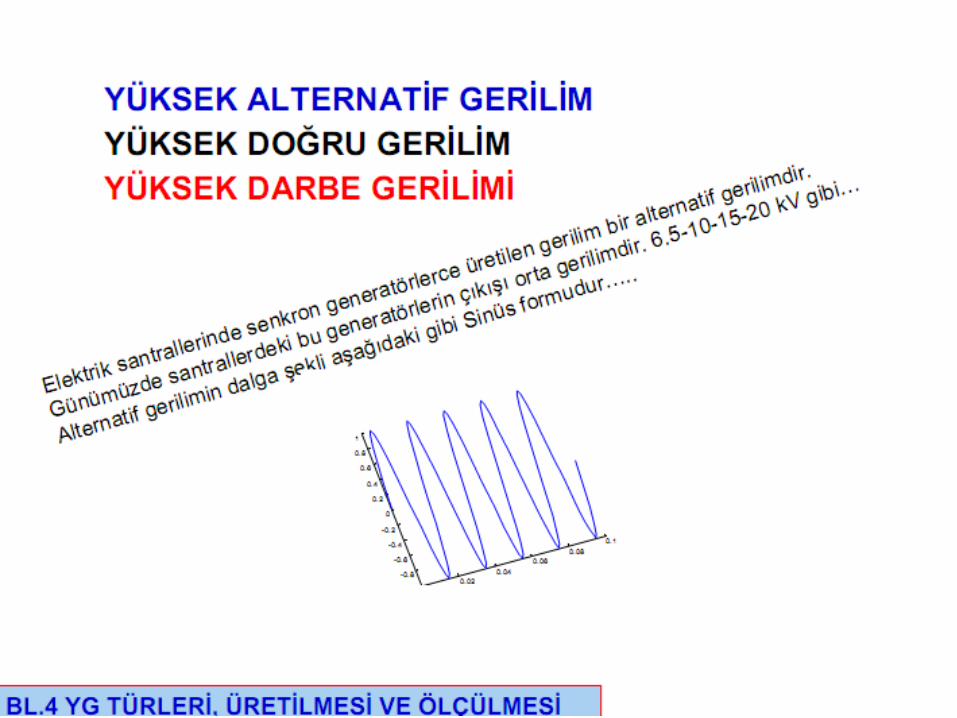
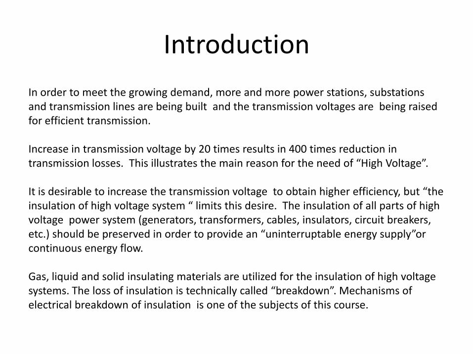
In order to meet the growing demand, more and more power stations, substations and transmission lines are being built and the transmission voltages are being raised for efficient transmission.
Increase in transmission voltage by 20 times results in 400 times reduction in transmission losses. This illustrates the main reason for the need of “High Voltage”.
It is desirable to increase the transmission voltage to obtain higher efficiency, but “the insulation of high voltage system “ limits this desire. The insulation of all parts of high voltage power system (generators, transformers, cables, insulators, circuit breakers, etc.) should be preserved in order to provide an “uninterruptable energy supply”or continuous energy flow.
Gas, liquid and solid insulating materials are utilized for the insulation of high voltage systems. The loss of insulation is technically called “breakdown”. Mechanisms of electrical breakdown of insulation is one of the subjects of this course.

Introduction
In High Voltage Installations Regulation (Elektrik Kuvvetli Akım Tesisleri Yönetmeliği) published by Turkey Ministry of Energy and Natural Sources ;
Low Voltage is the phase-phase voltage with rms value of 1000 Volts and less than1000 Volts
High Voltage is the phase-phase voltage with rms value of greater than 1000 Volts
These voltage ranges are also valid for IEC (International Electrotechnical Commission)
Definition of some important standardized rated insulation levels for high voltageequipment according to IEC 62271-1 is given above

Introduction
Rated voltage: Upper limit of the highest voltage of the network for which a switchingdevice is rated.
Rated short duration power frequency withstand voltage : rms value of the sinusoidala.c voltage at operating frequency that the insulation of a device must withstandunder the specified test conditions for 1 minute.
Rated lightning impulse withstand voltage: peak value of the standard voltage surge1.2/50us that the insulation of a device must withstand
Rated switching impulse withstand voltage: peak value of the unipolar standardvoltage surge 250/2500us which the insulation of a device with a rated voltage of 300 kV and above must withstand.


Introduction
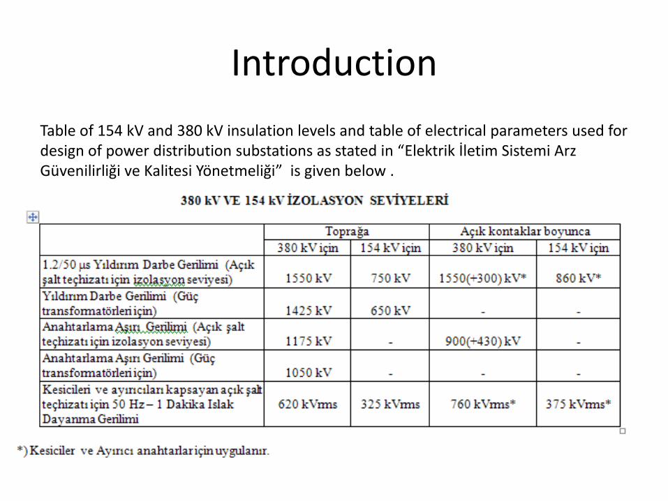
Table of 154 kV and 380 kV insulation levels and table of electrical parameters used for design of power distribution substations as stated in “Elektrik İletim Sistemi Arz Güvenilirliği ve Kalitesi Yönetmeliği” is given below .
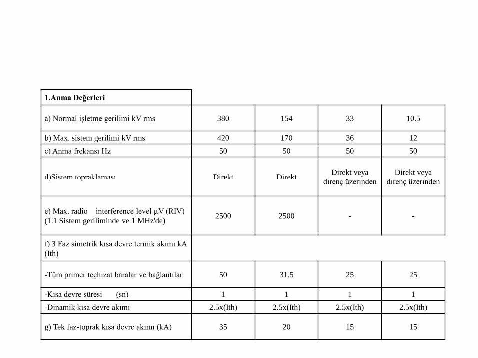
1.Anma Değerleri
a) Normal işletme gerilimi kV rms 380 154 33 10.5
b) Max. sistem gerilimi kV rms 420 170 36 12
c) Anma frekansı Hz 50 50 50 50
d)Sistem topraklaması Direkt DirektDirekt veya
direnç üzerinden
Direkt veya
direnç üzerinden
e) Max. radio interference level µV (RIV)
(1.1 Sistem geriliminde ve 1 MHz'de)2500 2500 - -
f) 3 Faz simetrik kısa devre termik akımı kA
(Ith)
-Tüm primer teçhizat baralar ve bağlantılar 50 31.5 25 25
-Kısa devre süresi (sn) 1 1 1 1
-Dinamik kısa devre akımı 2.5x(Ith) 2.5x(Ith) 2.5x(Ith) 2.5x(Ith)
g) Tek faz-toprak kısa devre akımı (kA) 35 20 15 15

2.İzolasyon Değerleri
(Güç Trafosu Hariç) 380 154 33 10.5
a) Yıldırım darbe dayanım
gerilimi kV-tepe
- Toprağa Karşı
- Açık Uçlar Arası
1550
1550(+300)
750
860170 75
b) Açma-kapama darbe dayanım
gerilimi kV-tepe
- Toprağa Karşı
- Açık Uçlar Arası
1175
(900+430)
- - -
c) 1 dakika Güç frekansında
dayanım gerilimi (yaşta)
kV-rms
-Toprağa Karşı
- Açık Uçlar Arası
620
760
325
37570 28
3.İzolasyon Değerleri
(Güç Trafosu için)
-Yıldırım darbe dayanım gerilimi
kV-tepe(faz-toprak)1425 650 170 95 (YG nötrü)
-Açma-kapama darbe dayanım
gerilimi kV-tepe 1050 - - -
-1dk. Güç frekansında dayanım
gerilimi (yaşta) kV-rms 630 275 70 38 (YG nötrü)
4.Yardımcı Servis Besleme Gerilimi :
-3faz-N AC sistem 380 V + % 10 - % 15, 50 Hz
-1faz-N AC sistem 220 V + % 10 - % 15, 50 Hz
- DC sistem 110 V (veya 220 V) + % 10 - % 15

Transmission of Electric Energy
Although the bulk of world’s electric transmission is carried on ac systems, recent
progress in high-voltage direct current (HVDC) technology has enabled the
development of large scale dc transmission by overhead lines and submarine cables
which have become economically attractive in long distance transmission of large bulk
power. HVDC permits a higher power density on a given right-of-way than a.c.
Transmission and thus helps the electric utilities in meeting the environmental
requirements imposed on the transmission of electric power.
HVDC transmission can transmit more power per line and is much more efficient and
cost effective over large distances. In addition the losses are quite low.

Transmission of Electric EnergyToday’s HVDC transmission schemes can carry up to 3000 MW of power over distances
between 1000 – 1500 km. Atypical scheme consists of two stations that convert AC to
DC and vice versa. It uses overhead lines or cables with only two conductors.

Transmission of Electric EnergyIncreasing demands and strict environmental regulations mean that more and more
remote hydro power plants are being considered. There is an almost unlimited source
of solar power. If it could be harnessed properly and combined with hydro, wind and
pump storage a totally renewable electrical system is possible.

Transmission of Electric Energy

Transmission of Electric Energy

Standards and Regulations
Standardization work for the field of electrical engineering is conducted almostentirely on an international level.
In Europe IEC (International Electrotechnical Commission), in USA ANSI (AmericanNational Standards Institute) are valid. There are other Canada, Russian and Japanstandards.
In Turkey TSE standards are valid. They are mostly Turkish versions of IEC standards.
Some of IEC standards related with hih voltage systems is listed below.

Standards and Regulations
• IEC 60038 Standard Voltages
• IEC 60265-1 High Voltage Switches - Switches for Rated Voltages above 1 KV and less than 52 KV
• IEC 60265-2 High Voltage Switches for Rated Voltages of 52 KV and above
• IEC 60282-1 High Voltage Fuses – Current Limiting Fuse
• IEC 62271-1 Common specifications for high voltage switchgear and controlgear standards
• IEC 62271-100 High voltage switchgear and controlgear -high voltage alternating current circuit breakers
• IEC 62271-102 High voltage switchgear and controlgear -alternating current disconnectors and earthing switches

Standards and Regulations
Besides standards there are also local regulations fortransmission, distribution of electric energy and energy market.
In Turkey EPDK is the regulating agency. Below are someimportant local regulations for energy market.
• Elektrik İletim Sistemi Arz Güvenilirliği ve Kalitesi Yönetmeliği
• Elektrik Kuvvetli Akım Tesisleri Yönetmeliği
• Elektrik Piyasası Şebeke Yönetmeliği

High Voltage Power System Components and Technology
Main components used in high voltage power systems are as follows:
• Synchronous generators
• Power transformers
• Disconnectors
• Circuit breakers
• Overhead lines and conductors
• Towers
• Insulators
• Cables
• Bus bars

High Voltage Power System Components and Technology
Measuring and protection components used in high voltage power systemsare as follows:
• Voltage and current transformers
• Relays
• Surge arresters
• Control circuits
• Voltage dividers
• Earthing switches
Voltage regulating components used in high voltage power systems are asfollows:
• Series and shunt reactors
• Series and shunt capacitors

Insulatorsto insulate means "to separate or cover with a nonconducting material in order to prevent the passage or leakage of electricity, heat, or sound." Communication and electric line wires in service must be kept as dry as possible in order to function efficiently, and to cut down on loss of current. The wires are kept off of the ground by being strung between poles. But something was needed to keep the wires and (sometimes wet) poles apart. This "something" had to meet three basic needs:
• it must be made of a fast-drying nonconducting material
• it must be able to hold the line wire in place
• it must stay on the pole
This "something" is the insulator. It was developed and improved upon over the years to meet those basic requirements is most commonly made of glass or porcelain
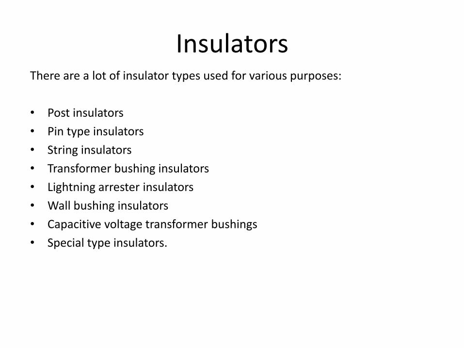
InsulatorsThere are a lot of insulator types used for various purposes:
• Post insulators
• Pin type insulators
• String insulators
• Transformer bushing insulators
• Lightning arrester insulators
• Wall bushing insulators
• Capacitive voltage transformer bushings
• Special type insulators.

Insulators

Insulators

Insulators

Insulators

Insulators

Disconnectors
Disconnectors are used for galvanic isolation of networks or sections ofswitchgear installations. As an independent air insulated-device, they form avisible isolating distance in their open position.
More than 10 different designs are in use around the world. The mostimportant are:
• knife -contact disconnectors
• rotary disconnectors
• two column vertical break disconnectors
• single-column disconnectors.

Disconnectors

Knife-contact disconnectorsThe classic design of the disconnector is the knife-contact disconnector. Theirmoving contacts have the knife shape. There are indoor and outdoor types.They can be actuated manually and in remotely operated installations bymotor or compressed air drives.

Indoor knife-contact disconnectorsIndoor types are used in switchgears in buildings. Control arm is brought outto a safe distance .
They are used in 10,15,30,45 KV systems with current ratings of 400, 630 and1250 Amps. They have a simple and standard structure. The parts are:chassis, post insulator, fixed and moving contacts and armed movingmechanism.

Outdoor knife-contact disconnectors
Outdoor types are used out of the buildings and are subject to environmentalconditions like rain, dust, wind etc.

Disconnectors with fuseThese connector include a pair of fuse for protection against short circuits.There are indoor and outdoor knife-types.
They are used at the feeders of consumers with low power demand, atmeasuring voltage transformer feeders, and at auxiliary transformer feedersfor substations.
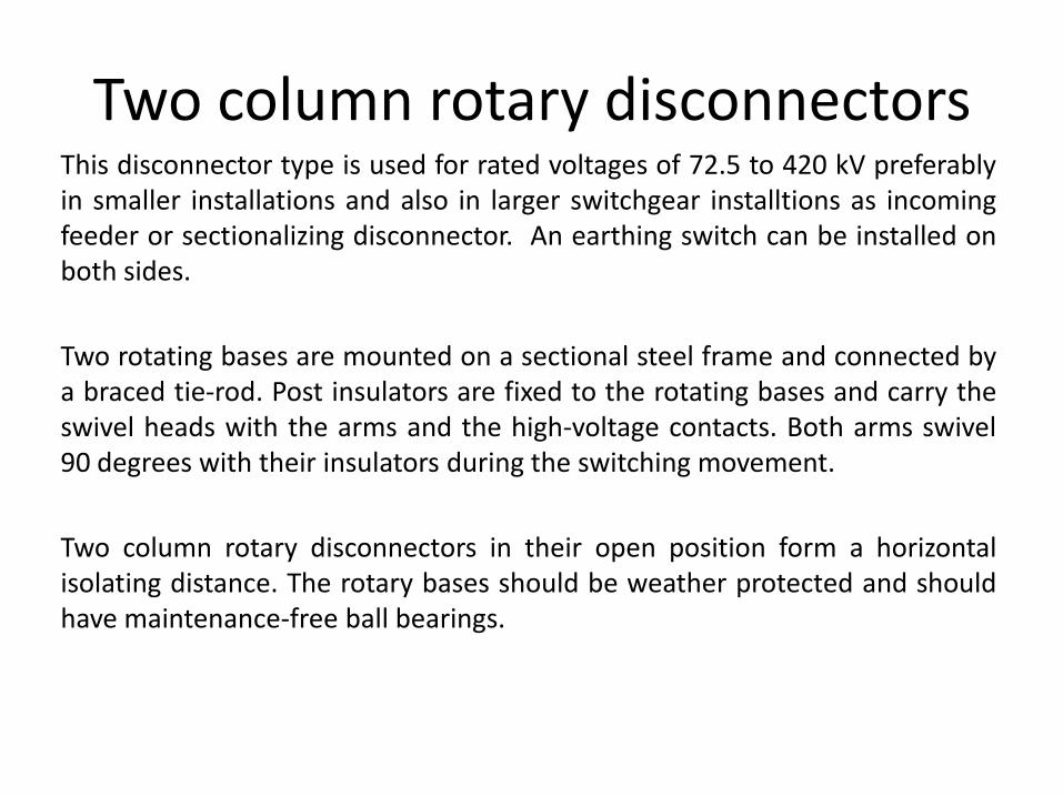
Two column rotary disconnectorsThis disconnector type is used for rated voltages of 72.5 to 420 kV preferablyin smaller installations and also in larger switchgear installtions as incomingfeeder or sectionalizing disconnector. An earthing switch can be installed onboth sides.
Two rotating bases are mounted on a sectional steel frame and connected bya braced tie-rod. Post insulators are fixed to the rotating bases and carry theswivel heads with the arms and the high-voltage contacts. Both arms swivel90 degrees with their insulators during the switching movement.
Two column rotary disconnectors in their open position form a horizontalisolating distance. The rotary bases should be weather protected and shouldhave maintenance-free ball bearings.

Two column rotary disconnectors

Two column rotary disconnectors

Three column rotary disconnectorsThese disconnector types are used with a side-by-side configuration of the three polesof a group. In comparison to two column rotary disconnectors, they allow smaller polespacings and higher mechanical terminal loads.
The two outer insulators are fixed to the base frame and carry the contact system. Themiddle insulator is fastened to a rotating base and carries the one-piece arm, whichrotates approximately 60 degrees during a switching operation and engages thecontact systems on the outer insulators.

Single column (pantograph) disconnectors
In installations for higher voltages (> 170 kV) and multiple busbars , the single columndisconnector (also referred to as pantograph or vertical-reach disconnector) requiresless space than other disconnector designs. For this reason and because of the clearstation layout , it is used in many switchgear installations. The switch status is clearlyvisible with the vertical isolating distance.
The base of the disconnector is the frame, which holds the post insulator carrying thehead piece with the pantograph and the gearbox. The actuating force is transferredthrough the rotating insulator to the gearbox. The suspended contact is mounted onthe busbar situated above the disconnector. On closing, it is gripped between thepantograph arms.
During the closing movement, the pantograph arms swivel through a wide range andare therefore capable of carrying the fixed contact even under extreme positionchanges caused by weather conditions. The feeder line is connected to the high-voltage terminal of the gearbox. In general, the single column disconnector allowshigher mechanical terminal loads than the two column rotary disconnector.

Single column (pantograph) disconnectors

Single column (pantograph) disconnectors

Single column (pantograph) disconnectors

Two column vertical-break disconnectors
This type of disconnector is preferred for higher voltages (>170 KV) as afeeder or branch disconnector. It differs from two-column rotarydisconnectors by smaller space savings (with side-by-side configuration) andhigher mechanical terminal loads. In its open state there is a horizontalisolating distance with the contact arm open upwards.
The two post insulators are mounted on a frame. The gearbox with contactarm and high-voltage terminal and the fixed contact with high-voltageterminal are mounted on them. The rotating insulator fastened to the rotarybearing transfers the actuating force to the gearbox, which transmits theforce into a torque for opening the contact arm.
For rated voltages up to 245 KV one mechanism per three-phase disconnectoris sufficient, at higher nominal voltages one mechanism per pole is generallyused.

Two column vertical-break disconnectors

Circuit BreakersHigh voltage circuit breakers are mechanical switching devices capable ofmaking, carrying continuously and breaking electrical currents both undernormal circuit conditions and for a limited period, abnormal circuit conditionssuch as in the event of a short circuit. Circuit breakers are used for switchingoverhead lines, cable feeders, transformers, reactor coils and capacitors. Theyare also used in bus ties in installations with multiple busbars to allow powerto be transmitted from one busbar to another.
The following points are important when selecting circuit breakers.
• Maximum operating voltage on location
• Maximum load current occurring on location
• Maximum short circuit current occurring on location
• Network frequency
• Duration of short circuit current
• Switching cycle
• Special operational and climatic conditions

Circuit BreakersImportant standards are
IEC
62271-1 General and definitions
62271-100 Classification, Design and construction, Type and routine testing,Selection of circuit breakers for service, Informationin enquiries, tenders andorders
ANSI (American National Standards Institute)
C37 04 – 1979 Rating structure
C37 06 – 1979 Preferred ratings
C37 09 – 1979 Test procedure
C37 10 – 1979 Application guide
C37 11 – 1979 Application guide for transient recovery voltage
C37 12 – 1979 Capacitance current switching

Electrical CharacteristicsRated value: Value of a characateristic quantity used to define the operatingconditions for which a switching device is designed and built and which mustbe verified by the manufacturer.
Rated normal current: The current that the main circuit of a switching devicecan continuously carry under specified conditions.
Rated short-time withstand current: Current that a switching device in closedposition can carry during a specified short-time under prescribed conditions.
Standardized rated normal currents: 200, 250, 400, 500, 630, 800, 1000,1250, 1600, 2000, 2500, 3150, 4000, 5000, 6300A.
Standardized rated short-time currents: 6.3, 8, 10, 12.5,16, 20, 25, 31.5, 40,50, 63, 80, 100 kA.

Electrical CharacteristicsRated voltage: upper limit of the highest voltage of the network for which aswitching device is rated.
Standardized rated voltages: 3.6, 7.2, 12, 17.5, 24, 36, 52, 72.5, 100, 123,145, 170, 245, 300, 362, 420, 550, 800 kV.
Peak making current: peak value of the first major loop of the current in onepole of a switching device during the transient period following the initiationof current during a making operation.
Breaking current: current in one pole of a switching device at the instant ofinitiation of an arc during a breaking process.

Electrical CharacteristicsApplied voltage: voltage between the terminals of a circuit breaker poleimmediately before making the current.
Recovery voltage: voltage occurring between the terminals of a circuitbreaker pole after interrruption of the current
Opening time: interval of time between application of auxiliary power to thecopening release of a switching device and the seperation of contacts in allthree poles.
Closing time: interval of time between application of auxiliary power to theclosing circuit of a switching device and the contact touch in all poles.
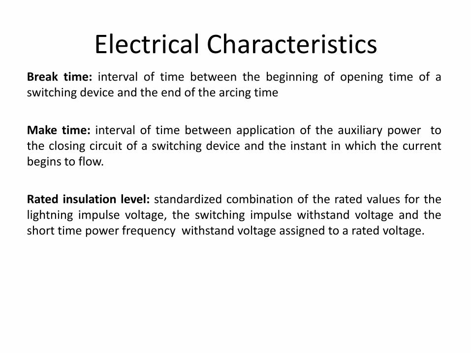
Electrical CharacteristicsBreak time: interval of time between the beginning of opening time of aswitching device and the end of the arcing time
Make time: interval of time between application of the auxiliary power tothe closing circuit of a switching device and the instant in which the currentbegins to flow.
Rated insulation level: standardized combination of the rated values for thelightning impulse voltage, the switching impulse withstand voltage and theshort time power frequency withstand voltage assigned to a rated voltage.

Electrical CharacteristicsRated short duration power frequency withstand voltage : rms value of the sinusoidal a.c voltage at operating frequency that the insulation of a device must withstand under the specified test conditions for 1 minute.
Rated lightning impulse withstand voltage: peak value of the standard voltage surge 1.2/50us that the insulation of a device must withstand
Rated switching impulse withstand voltage: peak value of the unipolar standard voltage surge 250/2500us which the insulation of a device with a rated voltage of 300 kV and above must withstand.

Electrical Characteristics
1. Transient recovery voltage e(t) system voltage2. Recovery voltage ea(t) arcing voltage3. Breaking time ik short circuit current

Circuit breaker typesThere are still a number of “small-oil-volume” circuit breakers in use for ratedvoltages up to 52 kV in systems, but for new installations only vacuum or SF6circuit breakers are used.
Circuit breakers can be stationary mounted or integrated into the panel inwithdrawable unit design ith appropriate interlocking mechanism.
Circuit breakers must be capable of making and breaking all-short circuit andservice currents occurring at the operational site.

Vacuum circuit breakersVacuum circuit breakers are available for short circuit breaking currents up to 63 KA with rated currents from 400 to 4000 A with rated voltages 12, 17.5, 24 and 36/40.5 KV.

Vacuum circuit breakers

Vacuum circuit breakersThe components of the main current path (upper breaker terminal, vacuuminterrupter, lower terminal etc.) are embedded in cast resin and thuscompletely enclosed by insulating material. The contacts arecopper/chromium composite material, a copper base containing evenlydistributed fine-grained chromium particles, which has a good extinguishingand arc-resistant response when switching short-circuit currents.
Vacuum circuit breaker contains no arc extinguishing and quenching media.

Vacuum circuit breakersActuating systems
The travel of the moving contact between the open and closed positions inthe vacuum circuit breaker is between 8 and 14 mm depending on the ratedvoltage. At the end of closing stroke , the energy for tensioning the contactpressure spring is required. The relatively low total energy requirement forvacuum circuit breaker is generally provided by mechanical spring storedenergy operating mechanisms. Tripping is initiated by magnetic releases ormanually.

SF6 circuit breakersSulphur hexafluoride (SF6) is an inert, heavy gas having good dielectric andarc extinguishing properties. The dielectric strength of the gas increases withpressure and is more than of dielectric strength of oil at 3 kg/cm2.
The puffer type arc quenching principle provides an effective arc-quenchinggas flow by a mechanically driven piston.

SF6 circuit breakers
During the arcing period SF6 gas is blown axially along the arc. The gas
removes the heat from the arc by axial convection and radial dissipation. As a
result, the arc diameter reduces during the decreasing mode of the current
wave. The diameter becomes small during the current zero and the arc is
extinguished. Due to its electronegativity, and low arc time constant, the SF6
gas regains its dielectric strength rapidly after the current zero, the rate of rise of
dielectric strength is very high and the time constant is very small.

SF6 circuit breakers

SF6 circuit breakers

SwitchgearThere are two types of switchgear commonly applied today for switching andprotection of high voltage power distribution systems. One is metal-cladswitchgear using draw-out circuit breakers and relays for protection. Theother is metal enclosed switchgear using interrupter switches for loadswitching and power fuses for fault protection. Metal-clad switchgearcontains drawout circuit breakers which are removed for required scheduledmaintenance and removal of a breaker interrupts its load. Metal-cladswitchgear also contains insulated bus which, when tested periodically, requires a shutdown of the gear.
Metalenclosed switchgear is available with interrupter switches and fusesthat require no scheduled maintenance, and the air-insulated bus does notrequire periodic dielectric testing. Annual maintenance normally
consists of little more than a visual inspection through the windows of the
gear. This switchgear should be seriously considered if only infrequent
Interruptions can be tolerated by plant operations.

SwitchgearSwitchgears are designed to comply with fixed minimum clearances of livecomponents from one another, from earth potential and from protectingbarriers.
When setting up these installations in electrical equipment rooms withrestricted accessibility, protection against accidental contact with livecomponents is sufficient.
Metal enclosed switchgear are generally assembled from type-tested panels.The metallic and earthed enclosure protects personnel against approach tolive components and against contact with moving parts. It also protects theinstallation against the penetration of foreign bodies.
Switchgear of this type has the largest market share worldwide.

Switchgear

Switchgear

Switchgear

Switchgear

Switchgear

SwitchgearA third type of switchgear is the gas insulated switchgear (GIS). The term “gas-insulated” refers to the fact that atmospheric air is not used as the gaseousinsulating material inside the panels, i.e. The enclosure of the installationmust be gas-tight against the environment.
The advantage of gas-insulated switchgear compared to an air insulatedinstallation is its independence from environmental influences such asmoisture, salt fog and pollution. This results in less maintenance, increaseoperational safety and high availability. The samller dimensions due tocompact design and increased dielectric resistance of the gaseous insulatingmaterial are also advantages.


Switchgear

Control systems for SwitchgearA wide range of devices for protection, control and monitoring tasks isavailable for conventional secondary technology in medium voltageswitchgear installations. The planning engineer selects the required units andcombines them into one installation. The outputs are predominantlystandardized to 1 A for current and 100 V for voltage.

Circuit breakers > 52 KVBasic design of HV outdoor circuit breakers with the following components isshown in the next figure: operating mechanism, insulators, interruptingchamber .
Higher voltages and higher capacities are dealt with by increasing the numberof interrupting chambers. Single chamber breakars are used for voltages up to300 KV and breaking currents of 50 KA. Multiple chamber breakers are usedfor higher currents up to 80 KA in this voltage range. Multiple chamberbreakers are used for voltages >300 KV.
In the lower voltage range and for three-phase autoreclosure, it is best tomount the three poles on a common base frame.
Single pole mounting and a seperate mechanism for each pole are standardfor voltages above 245KV.
The same interrupting chambers and mechanisms as indoor circuit breakersare also used with the integrated circuit breakers of gas insulated switchgearinstallations.

Circuit breakers > 52 KV

Circuit breakers > 52 KV

Circuit breakers > 52 KV

Circuit breakers > 52 KV

Circuit breakers > 52 KV

Circuit breakers > 52 KV

Some requirements for electrical control of circuit breakers
SF6 Gas monitoring : The breaking capacity of a circuit breaker is dependenton the gas density in the breaker chamber. This is measured by atemeperature-compensated pressure gauge. If the gas pressure falls toaspecified value, an alarm is triggered.
Local/remore control: To allow work on the breaker, it can generally becontrolled from the local control cubicle; control can be switched fromremote local by a selector switch.
Autoreclosing: A single or three-pole autoreclosing is selected on the type ofsystem earthing, the degree of the interconnection, the length of the linesand the amount of infeed from large power plants.

Instrument transformers for switchgear installations
Instrument transformers are transformers used to feed measuringinstruments, electricity meters, protection relays and similar equipment.
Their function is to transform high voltages and currents to values that canbe unified or measured safely with low internal losses. With currenttransformers , the primary winding carries the load current, while withvoltage transformers, the primary winding is connected to the service voltage.
The choice of a current transformer is based on the values of the primary andsecondary rated current, the rated output of the transformer cores at a givenaccuracy class rating and the overcurrent limit factor or accuracy limit factor.Selection of the values for the primary and secondary rated currents shouldbe based on standard levels. Secondary rated currents of 1A, 2A or 5A areavailable. Modern protection devices and measuring instruments have arelatively low burden, and so 1A is becoming the most frequently usedsecondary current.

Instrument transformers for switchgear installations
Measuring instruments or meters, for instance KW,KVAR or KWH measureunder normal load conditions. These devices require high accuracy, a lowburden and low saturation. They normally function in the range of 5-120% ofthe rated current in accordance with accuracy classes 0.2 to 0.5.
Burden is the load which may be imposed on a transformer secondary bycables and connected devices without causing an error greater than thestated accuracy classification.
For protection relays and disturbance recorders, the information about thefault on the primary side has to be transmitted to the secondary side.Measurement under fault conditions in the overcurrent range requires loweraccuracy, but the ability to transmit high fault currents which enable theprotection relay to measure and selectively shut down the fault. Typicalclasses are 5P, 10P or TP.
Several measuring and protection cores can be combined in each transformer.

Instrument transformers for switchgear installations

Instrument transformers for switchgear installations
Depending on the design of primary winding , current transformers aredivided into various types. This basically depends on the application (high orlow voltage).High voltage transformers are as a rule designed with oil-paperor SF6 insulation.

Instrument transformers for switchgear installations

Instrument transformers for switchgear installations

Instrument transformers for switchgear installations

Instrument transformers for switchgear installations
Voltage transformers can fundamentally be divided into two groups:inductive and capacitive voltage transformers. Inductive voltage transformersare the most economical solution for voltages up to 145 KV and above thatlevel capacitive transformers have advantages.
High voltage transformers are generally designed as oil-paper insulatedtransformers.
Apart from inductive voltage transformers, capacitive voltage transformersara available for higher system voltages up to 765 KV. They fundamentallyconsist of a capacitive divider and an inductive voltage transformer.

Instrument transformers for switchgear installations

Instrument transformers for switchgear installations

Instrument transformers for switchgear installations

Instrument transformers for switchgear installations
Optical current transformers use the Faraday effect in crystalline structures for passive measurement of currents. Monochromatic light is sent polarized into a solid body of glass, which surrounds the current carrying conductor. Reflection from the bewelled corners of the glass container directs the light beam around the conducting line before it exits again on one side.
The magnetic field around the conductor rotates the polarization plane of the light, whose phase difference is proportional to the magnetic field intensity H. The phase difference at the end of the path in the glass body is directly proportional to the current.

Instrument transformers for switchgear installations

Surge arrestersSurge arresters are used for protection of important equipment, particularly transformers, from atmospheric overvoltages and switching overvoltages.
Arresters are primarily selected on the basis of two basic requirements:
-the arrester must be designed for stable continuous operation
-it must provide sufficient protection for the protected equipment.
Today surge arresters are based on metal oxide (MO) resistors, which have an extremely nonlinear U/I characteristic and a high energy absorption capability. They are known as metal oxide surge arresters.
The metal oxide arrester is characterized electrically by a current/voltage curve. The current range is specified from the continuous operating range (range A of the curve, order of magnitude 10-3 A) to a minimum of the double value of the rated discharge current (order of magnitude 103 A). The MO arrester corresponding to the characteristic is transferred from the high resistance to the low resistance range at rising voltage without delay. When the voltage returns to the continuous operating voltage or below, the arrester becomes high ohmic.

Surge arresters

Surge arresters
Surge arresters are preferably installed parallel to the object to be protected between phase and earth.Because of the limited protection distance with steep lightning voltages, the arresters must be installed adjacent to the equipment that is to be protected as much as possible.
Monitoring systems (surge counters) may be used to monitor surge arresters. They are installed in the ground conductor of the arrester.

Surge arresters

Surge arresters

Transformers

Transformers

Oil Immersed Type Distribution Transformers
Hermetic With conservator
Iınside view

Dry Type Distribution Transformers
With tap changer In metal encase
Inside view

1.Core limbs
2.LV winding
3.HV winding
4.Tapping winding
5.Conductors
6.LV bushings
7.HV bushings
8.Pressing equipment
9. On-Load tap changer
10.Motor-drive mechanism
11.Oil conservator
12.Radiators
13. Tank

Stacking of core laminationsLifting up of the core with special apparatus.Three
limbed transformer
A transformer core with five limbs
Step-lapped core

The difference between Transformers and Reactors ; Reactors have only primary winding and their
core has air-gaps as shown below.(But their periodical test and maintenance are the same as
transformers except turn ratio and magnetizing current measurings)
Single
phase
reactor
core

Winding apparatus for disc winding
Winding apparatus for layer winding
Winding apparatus for layer winding
Vertical winding apparatus Pressing equipment for layer winding

INTRODUCTION
Active part of a transformer
Upper clamping ring
Bottom plate for the windings

INTRODUCTION
Active part with on-load tap changer
Active part with off-load tap changer
Due to the voltage variations in
the networks or in the substations,
transformers are normally equiped
with tapping windings having
necessary taps to accomplish the
requested voltage level. The
connections of these taps are
either made with no-load tap
changer(off-load tap changer)
when the transformer is
deenergized or with on-load tap
changer when the transformer is
under operating conditions.
The motor drive mechanism is
used for the, control of on-load tap
changer.This control can either be
made locally on the transformer or
remotely from the control
room.The operation of off-load tap
changers can either be made on
the cover or on the sidewall of the
transformer by manual drive
mechanism.Upon request, motor
drive mechanism can be provided
to operate the off-load tap
changers.

INTRODUCTION
Protection and control equipment
Bucholz relay
Pressure relief device
Oil level indicator
It is mounted on the pipe
connection from transformer tank
to conservator.The gasses which
occur in transformer for any
reason are collected here and
depending on the volume of gas it
gives an alarm or tripping signal.
It is mounted on the transformer
cover.It replies to the sudden
pressure increase that may occur
by an arc in the oil in the
transformer and gives tripping
signal by the contacts on itself.
It is mounted onto the sidewall
of the conservator. Depending
on the oil temperature
variations, it indicates the oil
level in conservator and gives
too low or too high indications
by the contacts on itself.

INTRODUCTION
Dehydrating breather
Oil thermometer
Winding thermometer
Oil flow indicator
It is mounted onto the
conservator.It takes the moisture
and dust in the air that enters the
conservator and increases service
security of the transformer, the
amount of silicagel particles in it
varies with the amount of the oil in
the transformer.
It controls the temperature of the oil in the
transformer tank and gives alarm and trip signal
at the adjusted temperature limits.It gives start
and stop signal for the fans used at forced
cooling.If remote control is required,Pt 100
resistance or 4-20 mA output is added to it.
It controls the temperature of the windings
with its monitoring circuit and gives alarm
and trip signal at the adjusted temperature
limits.Like the oil temperature,it is used for
the controls of fans and pumps and if reqired
Pt 100 resistance or 4-20 mA output is
added to it.
It controls the oil flow at forced oil cooled
transformers.It is mounted on the pipe
connection in which the oil flows
through.It gives alarm signal if the oil
does not flow for any reason.

HV
Bushin
g
turre
t
Air Cell
CT
031
oil te
mp. in
dic
ato
r
CT
033
win
din
g te
mp. in
dic
ato
r
AT
001
airc
ell
bre
ath
ing
CL060oil le
vel
CL064
oil le
vel O
LT
C
AT
005
OLT
C b
reath
ing
CF
050
BU
CH
HO
Z
CF101 air
cell alarm
relay
CP
096 p
ressure
relie
f valv
e fo
r OLT
C
BQ
011T
herm
om
ete
r pocket fo
r win
d. T
em
p.
BQ
010
Therm
om
ete
r pocket
CP
081 p
ressure
relie
f valv
e fo
r main
tank
RADIATOR
Main Tank
OLT
C b
ucholz
rela
yC
F 0
61

SECTION .2 - CONSTRUCTION
•O-ring
•Radiators (cooling elements)
•Oil Drain plug
• Air ejecting plug (vent screw)
•Lifting eye
Radiators are important part of the cooling of the transformers.Radiators have two ducts for connection to transformers.
On upper and bottom connection pipes ,there are butterfly valves.
On upper side there is a ventilation plug.
On bottom side there is a draining plug.
On top of it, there is a lifting eye.
Butterfly
valve
Transformer
Tank
RADIATORS

Ø The Fans and their Connections
SECTION .2 - CONSTRUCTION
FANCONTROL
CUBICLETANK
RADIATOR
FAN
Transformer Power Efficiency can be increased by adding fans. They are built under radiators to blow air upwards
for cooling the oil inside the radiators. They are operated automatically / manually when the oil temperature rise.
The basically cooling operations;
ONAN (Oil Natural Air Natural) (without fan or pumps)
ONAF (Oil Natural Air Forced) (air forced with fan)
OFAF (Oil Forced Air Forced) (air forced with fan or oil forced with pumps)

SECTION .2 - CONSTRUCTIONOLTC - MR Type

Transformers

Transformers

Transformers

Transformers

Transformers

Transformers

Transformers

Transformers

Transformers

Transformers

Transformers

HV Substations and Design Principles


HV Substations and Design Principles

HV Substations and Design Principles

HV Substations and Design Principles
HV Substations and Design Principles

HV Substations and Design Principles

HV Substations and Design Principles

HV Substations and Design Principles

HV Substations and Design Principles

HV Substations and Design Principles

HV Substations and Design Principles

HV Substations and Design Principles

HV Substations and Design Principles

HV Substations and Design Principles

HV Substations and Design Principles

HV Substations and Design Principles

HV Substations and Design Principles

HV Substations and Design Principles

HV Substations and Design Principles

HV Substations and Design Principles

HV Substations and Design Principles

HV Substations and Design Principles

HV Substations and Design Principles

HV Substations and Design Principles

HV Substations and Design Principles

HV Substations and Design Principles

HV Substations and Design Principles

HV Substations and Design Principles


Generation of High Voltages