
EE8403 MEASUREMENTS & INSTRUMENTATION LT P C 3 0 0 3 … · 2019-04-29 · EE8403 MEASUREMENTS &...
43
REGULATION: 2017 ACADEMIC YEAR: 2018-2019 JIT-JEPPIAAR/EEE/Ms.S.PRIYA/II YR /SEM / 04/EE8403/M&I/UNIT1-5/QB KEYS/VER 1.0 4.1 EE8403 MEASUREMENTS & INSTRUMENTATION LT P C 3 0 0 3 OBJECTIVES: To impart knowledge on the following Topics Basic functional elements of instrumentation Fundamentals of electrical and electronic instruments Comparison between various measurement techniques Various storage and display Various transducers and the data acquisition systems UNIT I INTRODUCTION 9 Functional elements of an instrument – Static and dynamic characteristics – Errors in measurement – Statistical evaluation of measurement data – Standards and calibration .Principle and types of analog and digital voltmeters, ammeters. UNIT II ELECTRICAL AND ELECTRONIC INSTRUMENTS 9 Principle and types of multi meters – Single and three phase watt meters and energy meters – Magnetic measurements – Determination of B-H curve and measurements of iron loss – Instrument transformers – Instruments for measurement of frequency and phase. UNIT III COMPARATIVE METHODS OF MEASUREMENTS 9 D.C potentiometers, D.C (Wheat stone, Kelvin and Kelvin Double bridge) & A.C bridges (Maxwell, Anderson and Schering bridges), transformer ratio bridges, self-balancing bridges. Interference & screening – Multiple earth and earth loops - Electrostatic and electromagnetic Interference –Grounding techniques. UNIT IV STORAGE AND DISPLAY DEVICES 9 Magnetic disk and tape – Recorders, digital plotters and printers, CRT display, digital CRO, LED, LCD & Dot matrix display – Data Loggers. UNIT V TRANSDUCERS AND DATA ACQUISITION SYSTEMS 9 Classification of transducers – Selection of transducers – Resistive, capacitive & inductive Transducers – Piezoelectric, Hall effect, optical and digital transducers – Elements of data acquisition system – Smart sensors-Thermal Imagers. TOTAL : 45 PERIODS OUTCOMES: To acquire knowledge on Basic functional elements of instrumentation. To understand the concepts of Fundamentals of electrical and electronic instruments. Ability to compare between various measurements techniques. To acquire knowledge on various storage and display devices. To understand the concepts various transducers and the data acquisition systems. Ability to model and analyze electrical and electronic Instruments and understand the operational features of display Devices and Data Acquisition System. TEXT BOOKS: 1. A.K. Sawhney, ‘A Course in Electrical & Electronic Measurements & Instrumentation’, Dhanpat Rai and Co, 2010. 2. J. B. Gupta, ‘A Course in Electronic and Electrical Measurements’, S. K. Kataria & Sons, Delhi, 2013. 3. Doebelin E.O. and Manik D.N., Measurement Systems – Applications and Design, Special Indian Edition, McGraw Hill Education Pvt. Ltd., 2007. REFERENCES: 1. H.S. Kalsi, ‘Electronic Instrumentation’, McGraw Hill, III Edition 2010. 2. D.V.S. Murthy, ‘Transducers and Instrumentation’, Prentice Hall of India Pvt Ltd, 2015. 3. David Bell, ‘ Electronic Instrumentation & Measurements’, Oxford University Press,2013. 4. Martin Reissland, ‘Electrical Measurements’, New Age International (P) Ltd., Delhi, 2001. 5. Alan. S. Morris, Principles of Measurements and Instrumentation, 2nd Edition, Prentice Hall of India, 2003.
Transcript of EE8403 MEASUREMENTS & INSTRUMENTATION LT P C 3 0 0 3 … · 2019-04-29 · EE8403 MEASUREMENTS &...
REGULATION: 2017 ACADEMIC YEAR: 2018-2019
JIT-JEPPIAAR/EEE/Ms.S.PRIYA/II YR /SEM / 04/EE8403/M&I/UNIT1-5/QB KEYS/VER 1.0 4.1
EE8403 MEASUREMENTS & INSTRUMENTATION LT P C
3 0 0 3
OBJECTIVES:
To impart knowledge on the following Topics
Basic functional elements of instrumentation
Fundamentals of electrical and electronic instruments
Comparison between various measurement techniques
Various storage and display
Various transducers and the data acquisition systems
UNIT I INTRODUCTION 9 Functional elements of an instrument – Static and dynamic characteristics – Errors in measurement –
Statistical evaluation of measurement data – Standards and calibration .Principle and types of analog and
digital voltmeters, ammeters.
UNIT II ELECTRICAL AND ELECTRONIC INSTRUMENTS 9 Principle and types of multi meters – Single and three phase watt meters and energy meters – Magnetic
measurements – Determination of B-H curve and measurements of iron loss – Instrument transformers –
Instruments for measurement of frequency and phase.
UNIT III COMPARATIVE METHODS OF MEASUREMENTS 9
D.C potentiometers, D.C (Wheat stone, Kelvin and Kelvin Double bridge) & A.C bridges (Maxwell,
Anderson and Schering bridges), transformer ratio bridges, self-balancing bridges. Interference & screening –
Multiple earth and earth loops - Electrostatic and electromagnetic Interference –Grounding techniques.
UNIT IV STORAGE AND DISPLAY DEVICES 9
Magnetic disk and tape – Recorders, digital plotters and printers, CRT display, digital CRO, LED, LCD & Dot
matrix display – Data Loggers.
UNIT V TRANSDUCERS AND DATA ACQUISITION SYSTEMS 9 Classification of transducers – Selection of transducers – Resistive, capacitive & inductive Transducers –
Piezoelectric, Hall effect, optical and digital transducers – Elements of data acquisition system – Smart
sensors-Thermal Imagers.
TOTAL : 45 PERIODS
OUTCOMES:
To acquire knowledge on Basic functional elements of instrumentation.
To understand the concepts of Fundamentals of electrical and electronic instruments.
Ability to compare between various measurements techniques.
To acquire knowledge on various storage and display devices.
To understand the concepts various transducers and the data acquisition systems.
Ability to model and analyze electrical and electronic Instruments and understand the operational features
of display Devices and Data Acquisition System.
TEXT BOOKS:
1. A.K. Sawhney, ‘A Course in Electrical & Electronic Measurements & Instrumentation’, Dhanpat Rai and
Co, 2010.
2. J. B. Gupta, ‘A Course in Electronic and Electrical Measurements’, S. K. Kataria & Sons, Delhi, 2013.
3. Doebelin E.O. and Manik D.N., Measurement Systems – Applications and Design, Special Indian Edition,
McGraw Hill Education Pvt. Ltd., 2007.
REFERENCES:
1. H.S. Kalsi, ‘Electronic Instrumentation’, McGraw Hill, III Edition 2010.
2. D.V.S. Murthy, ‘Transducers and Instrumentation’, Prentice Hall of India Pvt Ltd, 2015.
3. David Bell, ‘ Electronic Instrumentation & Measurements’, Oxford University Press,2013.
4. Martin Reissland, ‘Electrical Measurements’, New Age International (P) Ltd., Delhi, 2001.
5. Alan. S. Morris, Principles of Measurements and Instrumentation, 2nd Edition, Prentice Hall of India, 2003.
REGULATION: 2017 ACADEMIC YEAR: 2018-2019
JIT-JEPPIAAR/EEE/Ms.S.PRIYA/II YR /SEM / 04/EE8403/M&I/UNIT1-5/QB KEYS/VER 1.0 4.2
Subject code: EE8403 Year/semester:II/04
Subject Name: Measurements & Instrumentation Subject Handler: S.Priya
UNIT I INTRODUCTION 9 Functional elements of an instrument – Static and dynamic characteristics – Errors in measurement – Statistical
evaluation of measurement data – Standards and calibration Principle and types of analog and digital voltmeters,
ammeters.
PART * A
Q.No. Questions
1. What is an error? BTL 2
The algebraic difference b/w the indicated value and the true value of the quantity to be
measured is called an error.
2. When static characteristic are important?(NOV/DEC 2010) BTL 4
The instruments measure the quantity which do not vary with time, the static characteristic of an instruments play an important role.
3. When dynamic characteristic of an instruments are important? (April/May 2011) BTL 4
The instruments are subjected to rapidly varying inputs then it is necessary to study the dynamic
relations b/w input &output
4. What is an accuracy?(Apr/May 2015) BTL 2
It is the degree of closeness with which the instruments reading approaches the true value of the quantity to be measure.
5. What is precision? (NOV/DEC 2013) BTL 2
It is the measure of consistency or measurements. it denotes the amount by which the individual readings are departed about the average value of readings.
6.
What is sensitivity? (NOV/DEC 2013) BTL 2 It denotes the smallest change in the measured variable to which the instruments to be
responds. The units of sensitivity are in mm/unit quantity to be measure. Sensitivity= Change in output (response) of the instrument Change of input (or) measured variable
7. Define Threshold?( (NOV/DEC 2009) BTL 1
If the i/p quantity is slowly varied from zero onwards, the o/p does not vary until some min value of the i/p is reached.
8. Define resolution? (NOV/DEC 2009) BTL 1
It is the smallest increment of quantity being measured which can be certainly detected by an instrument.
9. What is linearity? (Apr/May 2015) BTL 2 It is the ability of an instrument to reproduce the input characteristic symmetrically & linearly.
10 Define tolerance? BTL 2 The max allowable error in the measurement is specified in terms of a value is called tolerance.
11
What is fidelity?(May/June 2014) BTL 2 It indicates how much faithfully the system reproduces the changes in the input. it is the ability
of an instruments to produce a wave shape identical to the wave shape of an input with respect to time.
12 What is an absolute instrument? (Apr/May 2015) BTL 2
The instrument which gives the magnitude of the quantity to be measure in termers of the physical constant of the instruments is called absolute instruments.
Mention the basic requirements of measurement. (May/June 2011) BTL 3
The standard used for comparison purpose must be accurately defined and should be
REGULATION: 2017 ACADEMIC YEAR: 2018-2019
JIT-JEPPIAAR/EEE/Ms.S.PRIYA/II YR /SEM / 04/EE8403/M&I/UNIT1-5/QB KEYS/VER 1.0 4.3
13 commonly accepted.
The apparatus used and the method adopted must be provable.
14
Explain the function of measurement system.(Nov/Dec 2011) BTL 3 The measurement system consists of a transducing element which converts the quantity to be
measured in an analogous form. The analogous signal is then processed by some intermediate means and is then fed to the end device which presents the results of the measurement.
15
The expected value of the voltage across a resistor is 40V. However the measurement gives a value of 39V. Calculate the absolute error. (May/June 2013) BTL 5 Absolute error= At-Am Expected value or true value,(At)= 40V Measured value or recorded value (Am)= 39V E= 40-39 =1 V.
16
Mention the types of instruments. BTL 4
The 3 types of instruments are
Mechanical Instruments
Electrical Instruments and
Electronic Instruments.
17
Give the applications of measurement systems. (Apr/May 2011) BTL 4
The instruments and measurement systems are used for
Monitoring of processes and operations.
Control of processes and operations.
Experimental engineering analysis.
18 Why calibration of instrument is important? (NOV/DEC 2013) BTL 3
The calibration of all instruments is important since it affords the opportunity to check the instrument against a known standard and subsequently to errors in accuracy.
19
Mention the calibration procedure. BTL 4 Calibration procedure involves a comparison of the particular instrument with either a primary
standard or a secondary standard with a higher accuracy than the instrument to be calibrated or an instrument of known accuracy.
20
Define Calibration. What is the significance of calibration? (Apr/May 2010) (Nov/Dec 2013)
BTL 1 It is the process by which comparing the instrument with a standard to correct the accuracy. Visual inspection for various defects Installation according to the specification Zero adjustment.
21
Define Drift. Mentions its Classifications. BTL 1
It is defined as for a given input, the measured values do not vary with tome. Drift is rarely
apparent and must be carefully guarded against by continuous inspection.
Zero drift
Span drift and sensitivity drift
Zonal drift
22
Define fidelity. BTL 1
It is the ability of an instrument to produce a wave shape identical to wave shape of input with
respect to time.
PART * B

REGULATION: 2017 ACADEMIC YEAR: 2018-2019
JIT-JEPPIAAR/EEE/Ms.S.PRIYA/II YR /SEM / 04/EE8403/M&I/UNIT1-5/QB KEYS/VER 1.0 4.4
1.
Describe the static and dynamic characteristics of measuring instrument. (13M)
(Apr/May 2011)(Nov 2018) BTL 2
Answer page : 1.8- J.Gnanavadivel
Static characteristics: (7M)
Accuracy: The closeness with which an instrument reading approaches the true value of the
quantity being measured.
Precision: It is a measure of reproducibility of the measurements, i.e., given a fixed value of
a quantity, precision is a measure of the degree of agreement with in a group of
measurements.
Static sensitivity: If the input is slowly increased from some arbitrary (non-zero) input value,
it will again be found that output does not change at all until a certain increment is exceeded.
Reproducibility: It is the degree of closeness with which a given value may be repeatedly
measured. It may be specified in terms of units for a given period of time.
Drift: Gradual change in instruments measurements.
Static error: Numerical differences between true value of a quantity and its value as obtained
by measurement.
Dead zone: It is defined as the largest change of input quantity for which there is no output
of the instrument.
Dynamic Characteristics: (6M)
Speed of response: The rapidity with which an instrument responds changes in measured
quantity.
Measuring lag: The difference between the true and measured value with no static error.
Fidelity: Delay in the response of an instrument to changes in the measured variable.
Dynamic error: The degree to which an instrument indicates the changes in the measured
variable without dynamic error (faithful reproduction).
2.
Discuss in detail various types of errors associated in measurement and how these errors can
be minimized? (13M) (Nov 2007) (Nov 2018) BTL 3
Answer page : 1.35- J.Gnanavadivel
Error: (2M)
The algebraic difference b/w the indicated value and the true value of the quantity to be
measured is called an error.
Types: (11M)
Static error: It is defined as the difference between the measured value and the true value of
the quantity under measurement.
Gross errors: is due to human fault.
Systematic errors:
1. Instrumental errors
2. Environmental errors
REGULATION: 2017 ACADEMIC YEAR: 2018-2019
JIT-JEPPIAAR/EEE/Ms.S.PRIYA/II YR /SEM / 04/EE8403/M&I/UNIT1-5/QB KEYS/VER 1.0 4.5
3. Observational errors
Random errors: due to causes that cannot be directly established.
Hysteresis error: Hysteresis is a non---coincidence of loading and unloading curves.
Hysteresis in a system arises due to the fact that all the energy put into the stressed parts
when loading is not recoverable upon unloading.
3.
Write briefly about Instrument Standards. (13M) (Apr 2008) BTL 3
Answer page : 1.33- J.Gnanavadivel
Standard in measurement: (3M)
A standard in measurements is a physical representation of an unit of measurement. The term
standard is applied to a piece of equipment having a known measure of physical quantity. They are
used for the purpose of obtaining the values of the physical properties of other equipments by
comparison methods.
Classifications of Standards (10M)
International Standards: Defined by International Agreement. Represent the closest
possible accuracy attainable by the current science and technology
Primary standards: Maintained at the National Std Lab (different for every country)
Function: the calibration and verification of secondary std Each lab has its own secondary
std which are periodically checked and certified by the National Std Lab. For example, in
Malaysia, this function is carried out by SIRIM.
Secondary standards: Secondary standards are basic reference standards used by
measurement and calibration laboratories in industries. Each industry has its own secondary
standard. Each laboratory periodically sends its secondary standard to the National
standards laboratory for calibration and comparison against the primary standard.
Working standards: Used to check and calibrate lab instrument for accuracy and
performance. For example, manufacturers of electronic components such as capacitors,
resistors and many more use a standard called a working standard for checking the
component values being manufactured.
4.
What are the basic blocks of a generalized instrumentation System. Draw the various blocks
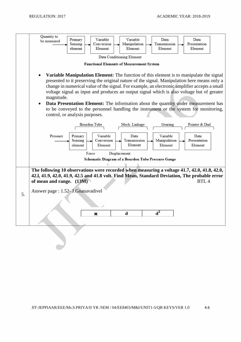
and explain their functional elements of an instrument. (13M) (Nov 2007) BTL 2
Answer page : 1.6- J.Gnanavadivel
Block diagram (6M ) & explanation (7M)
Primary sensing element: The quantity under measurement makes its first contact with the
primary sensing element of a measurement system. In other words the measurand is first
detected by primary sensor. This act is then immediately followed by the conversion of
measurand into an analogous electrical Signal.
Variable Conversion Element: The output of the primary sensing element may be
electrical signal of any form. It may be a voltage, a frequency or some other electrical
parameter. Sometimes this output is not suited to the system.
REGULATION: 2017 ACADEMIC YEAR: 2018-2019
JIT-JEPPIAAR/EEE/Ms.S.PRIYA/II YR /SEM / 04/EE8403/M&I/UNIT1-5/QB KEYS/VER 1.0 4.6
Variable Manipulation Element: The function of this element is to manipulate the signal
presented to it preserving the original nature of the signal. Manipulation here means only a
change in numerical value of the signal. For example, an electronic amplifier accepts a small
voltage signal as input and produces an output signal which is also voltage but of greater
magnitude.
Data Presentation Element: The information about the quantity under measurement has
to be conveyed to the personnel handling the instrument or the system for monitoring,
control, or analysis purposes.
5.
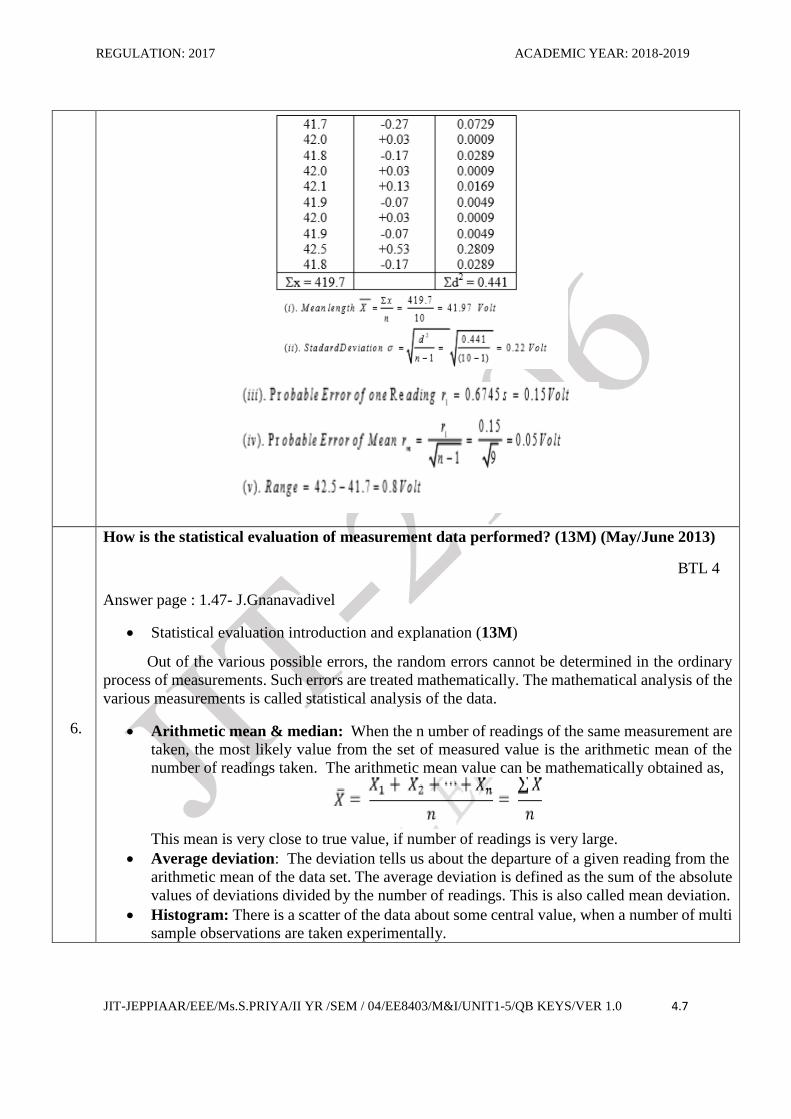
The following 10 observations were recorded when measuring a voltage 41.7, 42.0, 41.8, 42.0,
42.l, 41.9, 42.0, 41.9, 42.5 and 41.8 volt. Find Mean, Standard Deviation, The probable error
of mean and range. (13M) BTL 4
Answer page : 1.52- J.Gnanavadivel
REGULATION: 2017 ACADEMIC YEAR: 2018-2019
JIT-JEPPIAAR/EEE/Ms.S.PRIYA/II YR /SEM / 04/EE8403/M&I/UNIT1-5/QB KEYS/VER 1.0 4.7
6.
How is the statistical evaluation of measurement data performed? (13M) (May/June 2013)
BTL 4
Answer page : 1.47- J.Gnanavadivel
Statistical evaluation introduction and explanation (13M)
Out of the various possible errors, the random errors cannot be determined in the ordinary
process of measurements. Such errors are treated mathematically. The mathematical analysis of the
various measurements is called statistical analysis of the data.
Arithmetic mean & median: When the n umber of readings of the same measurement are
taken, the most likely value from the set of measured value is the arithmetic mean of the
number of readings taken. The arithmetic mean value can be mathematically obtained as,
This mean is very close to true value, if number of readings is very large.
Average deviation: The deviation tells us about the departure of a given reading from the
arithmetic mean of the data set. The average deviation is defined as the sum of the absolute
values of deviations divided by the number of readings. This is also called mean deviation.
Histogram: There is a scatter of the data about some central value, when a number of multi
sample observations are taken experimentally.
REGULATION: 2017 ACADEMIC YEAR: 2018-2019
JIT-JEPPIAAR/EEE/Ms.S.PRIYA/II YR /SEM / 04/EE8403/M&I/UNIT1-5/QB KEYS/VER 1.0 4.8
Range: The simplest possible measure of dispersion is the range which is the difference
between greatest and least values of data.
7.
Describe the different calibration procedure of measuring instrument. (13M) (Apr/May 2011)
BTL 4
Answer page : 1.54- J.Gnanavadivel
CALIBRATION : (3M)
Calibration is the process of making an adjustment or marking a scale so that the readings of
an instrument agree with the accepted & the certified standard. In other words, it is the procedure
for determining the correct values of measurand by comparison with the measured or standard ones.
The calibration offers a guarantee to the device or instrument that it is operating with required
accuracy, under stipulated environmental conditions.
Calibration methodologies: (10M)
Primary calibration
Secondary calibration
Direct calibration
Indirect
Routine
PART*C
1
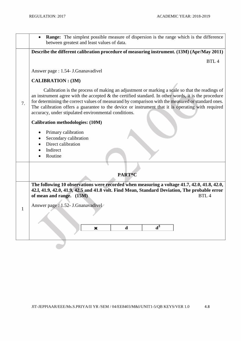
The following 10 observations were recorded when measuring a voltage 41.7, 42.0, 41.8, 42.0,
42.l, 41.9, 42.0, 41.9, 42.5 and 41.8 volt. Find Mean, Standard Deviation, The probable error
of mean and range. (15M) BTL 4
Answer page : 1.52- J.Gnanavadivel
REGULATION: 2017 ACADEMIC YEAR: 2018-2019
JIT-JEPPIAAR/EEE/Ms.S.PRIYA/II YR /SEM / 04/EE8403/M&I/UNIT1-5/QB KEYS/VER 1.0 4.9
2
Describe the static and dynamic characteristics of measuring instrument. (15M)
(Apr/May 2011) BTL 4
Answer page : 1.8- J.Gnanavadivel
Static characteristics: (8M)
Accuracy: The closeness with which an instrument reading approaches the true value of the
quantity being measured.
Precision: It is a measure of reproducibility of the measurements, i.e., given a fixed value of
a quantity, precision is a measure of the degree of agreement with in a group of
measurements.
Static sensitivity: If the input is slowly increased from some arbitrary (non-zero) input value,
it will again be found that output does not change at all until a certain increment is exceeded.
Reproducibility: It is the degree of closeness with which a given value may be repeatedly
measured. It may be specified in terms of units for a given period of time.
Drift: Gradual change in instruments measurements.
Static error: Numerical differences between true value of a quantity and its value as obtained
by measurement.
REGULATION: 2017 ACADEMIC YEAR: 2018-2019
JIT-JEPPIAAR/EEE/Ms.S.PRIYA/II YR /SEM / 04/EE8403/M&I/UNIT1-5/QB KEYS/VER 1.0 4.10
Dead zone: It is defined as the largest change of input quantity for which there is no output
of the instrument.
Dynamic Characteristics: (7M)
Speed of response: The rapidity with which an instrument responds changes in measured
quantity.
Measuring lag: The difference between the true and measured value with no static error.
Fidelity: Delay in the response of an instrument to changes in the measured variable.
Dynamic error: The degree to which an instrument indicates the changes in the measured variable
without dynamic error (faithful reproduction).
UNIT II ELECTRICAL AND ELECTRONIC INSTRUMENTS 9 Principle and types of multi meters – Single and three phase watt meters and energy meters – Magnetic
measurements – Determination of B-H curve and measurements of iron loss – Instrument transformers – Instruments
for measurement of frequency and phase.
PART * A
Q.No. Questions
1.
State the essentials torque required for successful operation of instruments? (Nov/Dec 2009)
BTL 4
Deflecting torque
Controlling torque
Damping torque
2. Why scale of gravity is non-uniform? (Apr/May 2015) BTL 4
The quantity is to measure is proportional to sin rather than in gravity control which is not a
uniform. Hence scale calibrated is not in uniform.
3. What is the basic principle of PMMC instruments? BTL 2
A current carrying coil placed in the permanent magnet field experiences a force, proportional to
the current it carries.
4.
List the possible cause of errors in moving iron instruments? (Apr/May 2015) BTL 3
Hysteresis errors.
Temperature errors.
Stray magnetic field errors Frequency & eddy current errors
6. What is loading effect? (Nov/Dec 2011) BTL 2
The low sensitive instruments is used in high resistances circuit then its gives a lower reading than the true reading.
7. State the precautions to be taken while using d.c. voltmeter? BTL 4
The voltmeter resistances are very high & it should always be connected across the circuit or component whose voltage is to be measure.
REGULATION: 2017 ACADEMIC YEAR: 2018-2019
JIT-JEPPIAAR/EEE/Ms.S.PRIYA/II YR /SEM / 04/EE8403/M&I/UNIT1-5/QB KEYS/VER 1.0 4.11
8. What are the requirements of a multiplier? (Nov/Dec 2010) BTL 2
Their resistances should not change with time.
They should not non-inductively wound for a.c.meters.
9. Which torque is absence in energy meter? BTL 3
The controlling torque is absence in energy metering energy meter continues rotation of disc is required & it is not necessary to reset it to zero every time & hence controlling torque is absence.
10
What are the constructional parts of dynamometer type wattmeter? BTL 2
Fixed coil
Moving Coil
Current limiting resister
Helical spring
Spindle attached with pointer Graduated scale
11
Name the errors caused in Dynamometer type wattmeter.(Nov/Dec 2013) BTL 2
Error due to pressure coil inductance
Error due to pressure coil capacitance
Error due to methods of connection
Error due to stray magnetic fields
Error due to eddy current.
12
Name the methods used for power measurement in three phase circuits.(Nov/Dec 2010)
BTL 2
Single wattmeter method
Two wattmeter method
Three wattmeter method.
13
What are the special features to be incorporated for LPF wattmeter? (Nov/Dec 2013) BTL 2
Pressure coil circuit
Compensation for Pressure coil current
Compensation for Pressure coil inductance.
14
Define creeping.(May/June 2014) BTL 1
Slow but continuous rotation of disc when pc is energized and cc is not energized.
16
Name the types of instruments used for making voltmeter and ammeter. (Nov/Dec 2013)
BTL 2
PMMC type
Moving iron type
Dynamometer type
Hot wire type
Electrostatic type
Induction type.
17 State the disadvantages of PMMC instruments. (Apr/May 2015) BTL 4
REGULATION: 2017 ACADEMIC YEAR: 2018-2019
JIT-JEPPIAAR/EEE/Ms.S.PRIYA/II YR /SEM / 04/EE8403/M&I/UNIT1-5/QB KEYS/VER 1.0 4.12
Cannot be used for ac m/s
Some errors are caused by temperature variations.
18 State the applications of PMMC instruments.(May/June 2012) BTL 2
m/s of dc voltage and current
Used in dc galvanometer.
19
How the range of instrument can be extended in PMMC instruments.(Nov/Dec 2011)
BTL 4
In ammeter by connecting a shunt resister
In voltmeter by connecting a series resister.
20
State the advantages of Hot wire type instruments. (Apr/May 2015) BTL 4
Can be used for both dc and ac
Unaffected by stray magnetic fields Readings are independent of frequency and waveform.
PART * B
1.
Describe the construction and working of permanent magnet moving coil instrument. Also
derive the expression for deflection. 13M (Nov/Dec 2013) BTL 3
Answer page: 2.14 – J.Gnanavadivel
Construction and working: (7m)
REGULATION: 2017 ACADEMIC YEAR: 2018-2019
JIT-JEPPIAAR/EEE/Ms.S.PRIYA/II YR /SEM / 04/EE8403/M&I/UNIT1-5/QB KEYS/VER 1.0 4.13
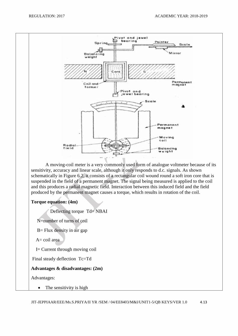
A moving-coil meter is a very commonly used form of analogue voltmeter because of its
sensitivity, accuracy and linear scale, although it only responds to d.c. signals. As shown
schematically in Figure 6.2, it consists of a rectangular coil wound round a soft iron core that is
suspended in the field of a permanent magnet. The signal being measured is applied to the coil
and this produces a radial magnetic field. Interaction between this induced field and the field
produced by the permanent magnet causes a torque, which results in rotation of the coil.
Torque equation: (4m)
Deflecting torque Td= NBAI
N=number of turns of coil
B= Flux density in air gap
A= coil area
I= Current through moving coil
Final steady deflection Tc=Td
Advantages & disadvantages: (2m)
Advantages:
The sensitivity is high
REGULATION: 2017 ACADEMIC YEAR: 2018-2019
JIT-JEPPIAAR/EEE/Ms.S.PRIYA/II YR /SEM / 04/EE8403/M&I/UNIT1-5/QB KEYS/VER 1.0 4.14
Uniform scale
Operating current is small
Disadvantages:
Not suitable for AC measurements
Ageing of PMMC introduces the errors
Cost is high
2.
With a neat block diagram explain the working of a digital multimeter. (13M) BTL 2 Answer page: 2.71 – J.Gnanavadivel
Draw the circuit diagram of Digital multimeter & explain its working (10M)
Digital multimeter is an instrument which can be used for measuring d.c and a.c voltages,
direct and alternating currents, and resistances over several ranges.
For measurement of a.c voltages and currents, the ac values are converted to dc value by
using rectifier and filter circuits & corresponding dc volatges are measured using the basic
circuit. Advantages & disadvantages(3m) Adv
1. Highly accurate and the accuracy is around 0.03 % 2. Loading effect is nil because of high input impedance 3. Measurement speed is more
Dis-Adv: 1. Interruption of electric noise 2. Requirement of external power supply 3. Isolation problems occurs in DMM.
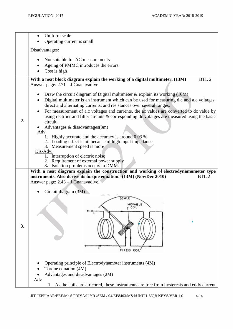
3.
With a neat diagram explain the construction and working of electrodynamometer type
instruments. Also derive its torque equation. (13M) (Nov/Dec 2010) BTL 2
Answer page: 2.43 – J.Gnanavadivel
Circuit diagram (3M)
Operating principle of Electrodynamoter instruments (4M)
Torque equation (4M)
Advantages and disadvantages (2M)
Adv 1. As the coils are air cored, these instruments are free from hysteresis and eddy current
REGULATION: 2017 ACADEMIC YEAR: 2018-2019
JIT-JEPPIAAR/EEE/Ms.S.PRIYA/II YR /SEM / 04/EE8403/M&I/UNIT1-5/QB KEYS/VER 1.0 4.15
losses. 2. They have a precision grade accuracy for frequencies from 40 HZ to 500 Hz.
Dis-Adv 1. They have a low torque/ weight ratio hence have a low sensitivity 2. Increases frictional losses.
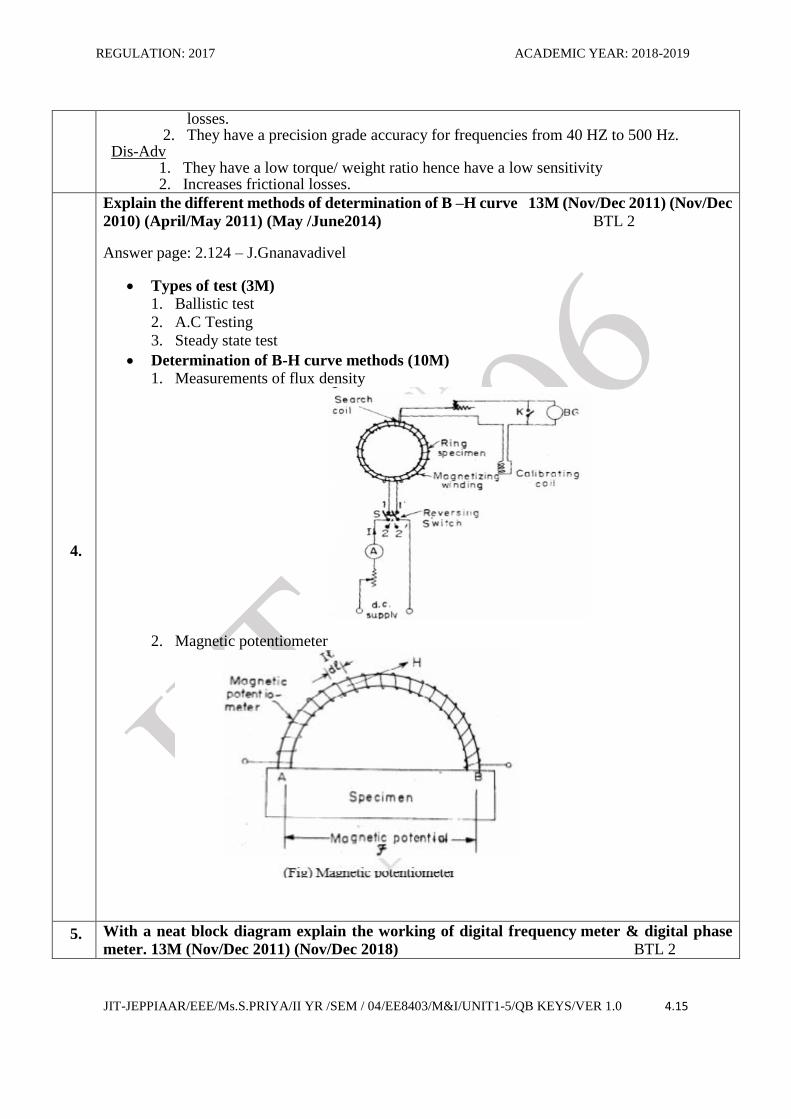
4.
Explain the different methods of determination of B –H curve 13M (Nov/Dec 2011) (Nov/Dec
2010) (April/May 2011) (May /June2014) BTL 2
Answer page: 2.124 – J.Gnanavadivel
Types of test (3M)
1. Ballistic test
2. A.C Testing
3. Steady state test
Determination of B-H curve methods (10M)
1. Measurements of flux density
2. Magnetic potentiometer
5. With a neat block diagram explain the working of digital frequency meter & digital phase
meter. 13M (Nov/Dec 2011) (Nov/Dec 2018) BTL 2
REGULATION: 2017 ACADEMIC YEAR: 2018-2019
JIT-JEPPIAAR/EEE/Ms.S.PRIYA/II YR /SEM / 04/EE8403/M&I/UNIT1-5/QB KEYS/VER 1.0 4.16
Answer page: 2.115 – J.Gnanavadivel
Circuit diagram & explanation (9M)
Electrodynamic instruments are capable of service as transfer instruments. Indeed, their
principal use as ammeters and voltmeters in laboratory and measurement work is for the
transfer calibration of working instruments and as standards for calibration of other
instruments as their accuracy is very high.
Electrodynamometer types of instruments are used as a.c. voltmeters and ammeters both in
the range of power frequencies and lower part of the audio power frequency range. They
are used as watt-meters, and with some modification as power factor meters and frequency
meters.
Advantages (2M)
1. Simple in construction
2. Simple operation
3. Gives an accurate measurement.
Dis-advantages of phase meter(2M)
1. Poor accuracy
2. The phase difference of 180 out of phase or inphase condition only can be detected.
Other phase angles cannot be measured.
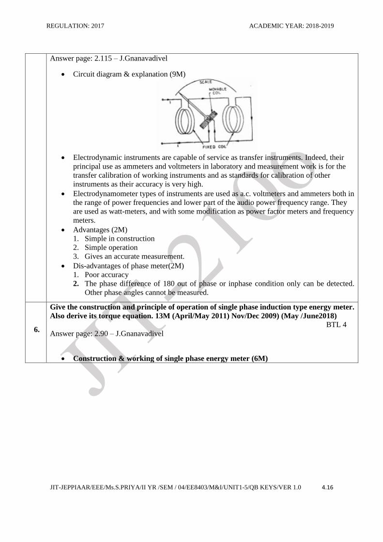
6.
Give the construction and principle of operation of single phase induction type energy meter.
Also derive its torque equation. 13M (April/May 2011) Nov/Dec 2009) (May /June2018)
BTL 4
Answer page: 2.90 – J.Gnanavadivel
Construction & working of single phase energy meter (6M)
REGULATION: 2017 ACADEMIC YEAR: 2018-2019
JIT-JEPPIAAR/EEE/Ms.S.PRIYA/II YR /SEM / 04/EE8403/M&I/UNIT1-5/QB KEYS/VER 1.0 4.17
Explanation (4M)
1. Driving system
2. Moving system
3. Braking system
4. Counting system/ Registering mechanism
Errors caused by braking system & advantages (3M)
7.
Explain with neat diagram the working of linear ramp type & integrating type DVM. (13M)
(April/May 2011) BTL 2
Answer page: 2.55 – J.Gnanavadivel
Ramp type DVM(6M)
1. The operating principle of a ramp type digital voltmeter is to measure the time that a
linear ramp voltage takes to change from level of input voltage to zero voltage (or vice
versa)
2. This time interval is measured with an electronic time interval counter and the count is
displayed as a number of digits on electronic indicating tubes of the output readout of
the voltmeter.
Integrating type DVM (7M)

REGULATION: 2017 ACADEMIC YEAR: 2018-2019
JIT-JEPPIAAR/EEE/Ms.S.PRIYA/II YR /SEM / 04/EE8403/M&I/UNIT1-5/QB KEYS/VER 1.0 4.18
8.
Explain the operating principle of Instrument Transformer and what are errors affecting its
charactersistics. (13M) (April/May 2011) (Nov/Dec 2018) BTL 2
Answer page: 2.99 – J.Gnanavadivel
Instrument transformer circuit diagram (5M)
REGULATION: 2017 ACADEMIC YEAR: 2018-2019
JIT-JEPPIAAR/EEE/Ms.S.PRIYA/II YR /SEM / 04/EE8403/M&I/UNIT1-5/QB KEYS/VER 1.0 4.19
Types & explanation (5M)
1. Current transformer
2. Potential transformer
Equivalent circuit (3M)
9.
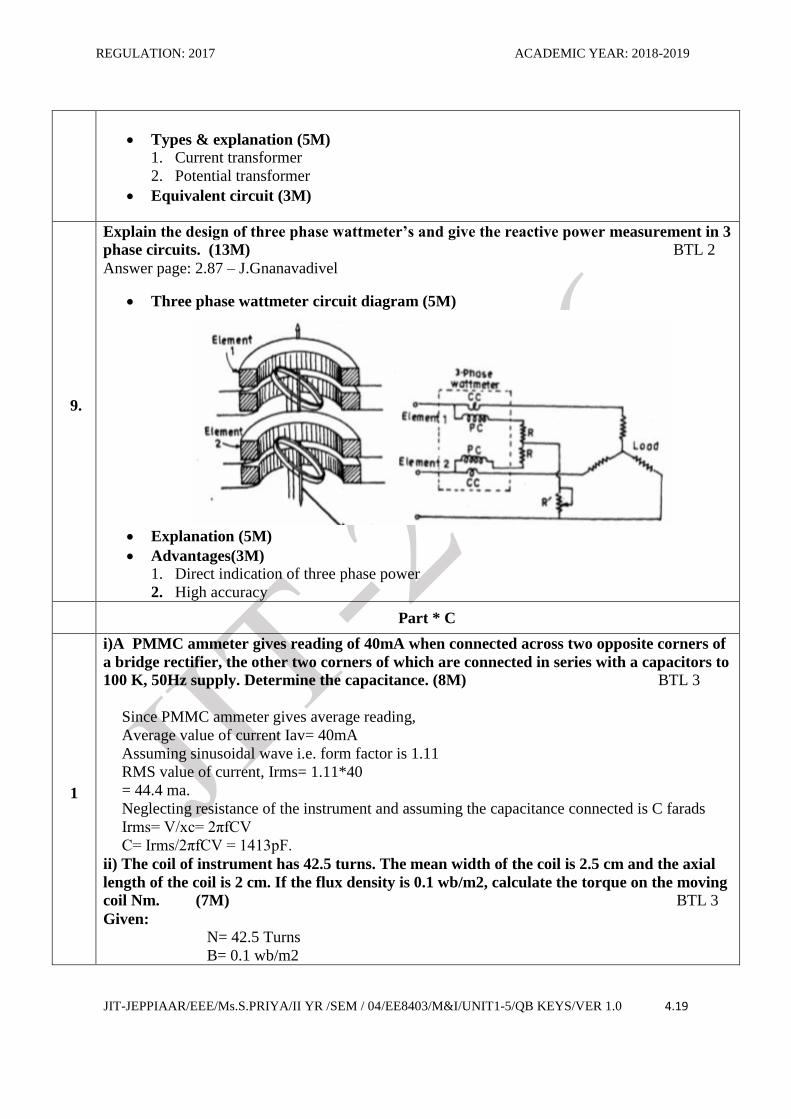
Explain the design of three phase wattmeter’s and give the reactive power measurement in 3
phase circuits. (13M) BTL 2
Answer page: 2.87 – J.Gnanavadivel
Three phase wattmeter circuit diagram (5M)
Explanation (5M)
Advantages(3M)
1. Direct indication of three phase power
2. High accuracy
Part * C
1
i)A PMMC ammeter gives reading of 40mA when connected across two opposite corners of
a bridge rectifier, the other two corners of which are connected in series with a capacitors to
100 K, 50Hz supply. Determine the capacitance. (8M) BTL 3
Since PMMC ammeter gives average reading,
Average value of current Iav= 40mA
Assuming sinusoidal wave i.e. form factor is 1.11
RMS value of current, Irms= 1.11*40
= 44.4 ma.
Neglecting resistance of the instrument and assuming the capacitance connected is C farads
Irms= V/xc= 2πfCV
C= Irms/2πfCV = 1413pF.
ii) The coil of instrument has 42.5 turns. The mean width of the coil is 2.5 cm and the axial
length of the coil is 2 cm. If the flux density is 0.1 wb/m2, calculate the torque on the moving
coil Nm. (7M) BTL 3
Given:
N= 42.5 Turns
B= 0.1 wb/m2
REGULATION: 2017 ACADEMIC YEAR: 2018-2019
JIT-JEPPIAAR/EEE/Ms.S.PRIYA/II YR /SEM / 04/EE8403/M&I/UNIT1-5/QB KEYS/VER 1.0 4.20
L=2 cm
D= 2.5 cm
Assume current i= 20mA
T= NBAi
= 42.5* 0.1 * 2.5 * 20 * 10-3
= 0.425N-M.
2
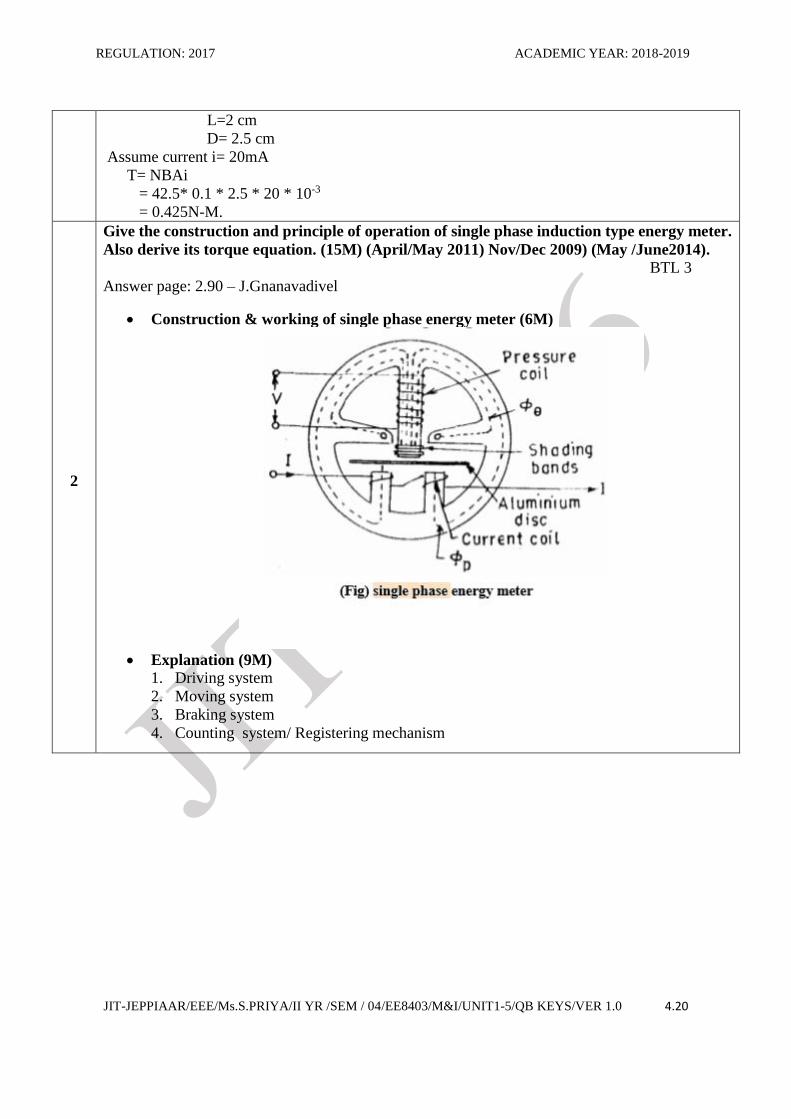
Give the construction and principle of operation of single phase induction type energy meter.
Also derive its torque equation. (15M) (April/May 2011) Nov/Dec 2009) (May /June2014).
BTL 3
Answer page: 2.90 – J.Gnanavadivel
Construction & working of single phase energy meter (6M)
Explanation (9M)
1. Driving system
2. Moving system
3. Braking system
4. Counting system/ Registering mechanism
REGULATION: 2017 ACADEMIC YEAR: 2018-2019
JIT-JEPPIAAR/EEE/Ms.S.PRIYA/II YR /SEM / 04/EE8403/M&I/UNIT1-5/QB KEYS/VER 1.0 4.21
UNIT III COMPARATIVE METHODS OF MEASUREMENTS 9
D.C potentiometers, D.C (Wheat stone, Kelvin and Kelvin Double bridge) & A.C bridges
(Maxwell, Anderson and Schering bridges), transformer ratio bridges, self-balancing bridges.
Interference & screening – Multiple earth and earth loops - Electrostatic and electromagnetic
Interference –Grounding techniques.
PART * A
Q.No. Questions
1.
What is potentiometer? BTL 2
A potentiometer is an instrument designed to measure an unknown voltage by comparing it
with a known voltage.
2. Define standardization. BTL 1
It is the process by which adjusting the current flows through the potentiometer coil to make the voltage across the std cell is equal.
3.
State the applications of potentiometer.(Nov/Dec 2011) BTL 5
Used for m/s of unknown emf
Used for ammeter calibration
Used for Voltmeter calibration
Used for wattmeter calibration
4.
What are the practical difficulties in ac potentiometers? (Apr/May2011) (BTL 2)
More complicated
Accuracy is seriously affected
Difficulty is experienced in standardization.
5.
State the advantages of ac potentiometers. (Apr/May 2015) BTL 5
Can be used for m/s of both magnitude and phase angle
Can be used for m/s of inductance of the coil.
It is used in m/s of errors in CTS
6.
State the applications of ac potentiometers.(Nov/Dec 2010) BTL 5
M/s of self-inductance.
Ammeter calibration
Voltmeter calibration
Wattmeter calibration.
7.
Name the bridge circuits used for the m/s of self-inductance. (Nov/Dec 2011) BTL 2
Maxwell’s bridge
Maxwell-Wein Bridge
Anderson bridge
Hay’s bridge.
8. Name the bridge circuits used for the m/s of mutual inductance.(May/June 2014) BTL 2
The Heaviside Campbell Bridge
The Campbell Bridge.
REGULATION: 2017 ACADEMIC YEAR: 2018-2019
JIT-JEPPIAAR/EEE/Ms.S.PRIYA/II YR /SEM / 04/EE8403/M&I/UNIT1-5/QB KEYS/VER 1.0 4.22
9.
Name the ac sources used in ac bridges.(Nov/Dec 2012) BTL 2
AC supply with step-down transformer
Motor driven alternator
Audio frequency and radio frequency oscillator.
10
Name the sources of errors in ac bridge (May/June 2014) BTL 2
Errors due to stray magnetic fields
Leakage errors Eddy current errors
Residual errors
Frequency and waveform errors.
11 Define Q-factor of the coil. B TL 1 It is the ratio between Power stored in the coil to the power dissipated in the coil
12
Name the faults that occur in cables. (Apr/May 2010) BTL 2
Break down of cable insulation
Short circuit fault
Open conductor fault.
13
Mention different types of resistance. (Apr/May 2015) BTL 2
Low resistance
Medium resistance
High resistance
14
Name the methods used for low resistance measurement.(Apr/May 2010) BTL 2
Ammeter – voltmeter method
Potentiometer method
Kelvin double bridge method
Ohm meter method
15
Name the methods used for medium resistance measurement. (Nov/Dec 2009) BTL 2
Ammeter – voltmeter method
Substitution method
Wheatstone bridge method
Carey fosters bridge method.
16
Where high resistance measurements is required? (Nov/Dec 2009) BTL 2
Insulation resistance of cables
High resistance circuit elements
Volume resistivity of a material
Surface resistivity.
17
State the applications of ac potentiometers.(Nov/Dec 2010) BTL 5
Measurements of self-inductance.
Ammeter calibration
Voltmeter calibration
Wattmeter calibration.
18 State the advantages of Kelvin double bridge method. BTL 5 Errors owing to contact resistance, resistance of leads can be eliminated by using This
REGULATION: 2017 ACADEMIC YEAR: 2018-2019
JIT-JEPPIAAR/EEE/Ms.S.PRIYA/II YR /SEM / 04/EE8403/M&I/UNIT1-5/QB KEYS/VER 1.0 4.23
Kelvin double bridge.
19
Name the sources of errors in ac bridge measurements. (May/June 2014) BTL 2
Errors due to stray magnetic fields
Leakage errors Eddy current errors
Residual errors
Frequency and waveform errors.
20 How the earth resistance is measured. BTL 5
By using earth megger the value of surface earth resistance can be measured.
21
Name the faults that occur in cables. (Apr/May 2010) BTL 2
Break down of cable insulation
Short circuit fault
Open conductor fault.
22
Name the methods used for low resistance measurement.(Apr/May 2010) BTL 2
Ammeter – voltmeter method
Potentiometer method
Kelvin double bridge method
Ohm meter method.
23
Name the methods used for medium resistance measurement. (Nov/Dec 2009) BTL 2
Ammeter – voltmeter method
Substitution method
Wheatstone bridge method
Carey fosters bridge method.
24
Where high resistance m/s is required? (Nov/Dec 2009) BTL 2
Insulation resistance of cables
High resistance circuit elements
Volume resistivity of a material
Surface resistivity.
PART * B
.
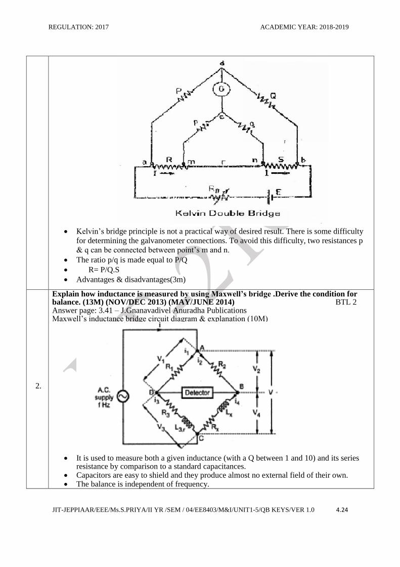
Explain the theory and working principle of Kelvin’s double bridge method for the
measurement of low resistance. Derive the relation for finding unknown resistance.
(13M)(NOV/DEC 2011)(MAY/JUNE 2014) (APR/MAY 2015) (APR/MAY 2010) BTL 2
Answer page: 3.30 – M.Sudakaran Lakshmi publications
Kelvin’s double bridge method circuit diagram & explanation (10M)
REGULATION: 2017 ACADEMIC YEAR: 2018-2019
JIT-JEPPIAAR/EEE/Ms.S.PRIYA/II YR /SEM / 04/EE8403/M&I/UNIT1-5/QB KEYS/VER 1.0 4.24
Kelvin’s bridge principle is not a practical way of desired result. There is some difficulty
for determining the galvanometer connections. To avoid this difficulty, two resistances p
& q can be connected between point’s m and n.
The ratio p/q is made equal to P/Q
R= P/Q.S
Advantages & disadvantages(3m)
2.
Explain how inductance is measured by using Maxwell’s bridge .Derive the condition for balance. (13M) (NOV/DEC 2013) (MAY/JUNE 2014) BTL 2 Answer page: 3.41 – J.Gnanavadivel Anuradha Publications Maxwell’s inductance bridge circuit diagram & explanation (10M)
It is used to measure both a given inductance (with a Q between 1 and 10) and its series
resistance by comparison to a standard capacitances. Capacitors are easy to shield and they produce almost no external field of their own. The balance is independent of frequency.
REGULATION: 2017 ACADEMIC YEAR: 2018-2019
JIT-JEPPIAAR/EEE/Ms.S.PRIYA/II YR /SEM / 04/EE8403/M&I/UNIT1-5/QB KEYS/VER 1.0 4.25
Using Q-factor for a series L-R equivalent circuit, the series resistances can be found from Rx=wLx/Q
Advantages & disadvantages(3m) Adv:
The frequency does not appear in any of the two equations. The two balance equations are independent, if the values of R1 & C1 as variable elements.
Dis adv: This bridge is limited to measurement of low Q coils It requires a variable standard capacitor which may be very expensive if calibrated to a
high degree of accuracy.
3.
Explain the working principle of Anderson’s bridge and also derive its balance
equations. (13M) BTL 2
Answer Page: 3.46 - J.Gnanavadivel Anuradha Publications
Andersons bridge circuit diagram & explanation (10M)
Advantages & disadvantages (3M)
Adv:
A fixed capacitor can be used instead of a variable capacitors in the case of Maxwell’s
bridge.
This bridge may be used for accurate determination of capacitance in terms of inductance.
Dis-Adv:
The Anderson’s bridge is more complex than its prototype Maxwell’s bridge.
An additional junction increases the difficulty of shielding the bridge.
4.
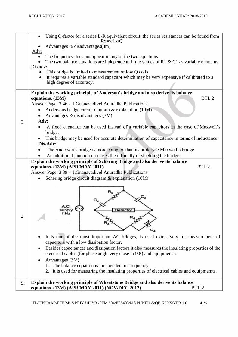
Explain the working principle of Schering Bridge and also derive its balance
equations. (13M) (APR/MAY 2011) BTL 2
Answer Page: 3.39 - J.Gnanavadivel Anuradha Publications
Schering bridge circuit diagram & explanation (10M)
It is one of the most important AC bridges, is used extensively for measurement of
capacitors with a low dissipation factor.
Besides capacitances and dissipation factors it also measures the insulating properties of the
electrical cables (for phase angle very close to 90ᵒ) and equipment’s.
Advantages (3M) 1. The balance equation is independent of frequency.
2. It is used for measuring the insulating properties of electrical cables and equipmemts.
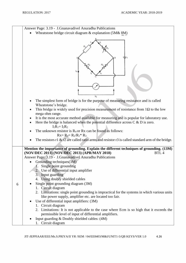
5. Explain the working principle of Wheatstone Bridge and also derive its balance
equations. (13M) (APR/MAY 2011) (NOV/DEC 2012) BTL 2
REGULATION: 2017 ACADEMIC YEAR: 2018-2019
JIT-JEPPIAAR/EEE/Ms.S.PRIYA/II YR /SEM / 04/EE8403/M&I/UNIT1-5/QB KEYS/VER 1.0 4.26
Answer Page: 3.19 - J.Gnanavadivel Anuradha Publications
Wheatstone bridge circuit diagram & explanation (5M& 8M)
The simplest form of bridge is for the purpose of measuring resistance and is called
Wheatstone’s bridge.
This bridge is widely used for precision measurement of resistance from 1Ω to the low
mega ohm range.
It is the most accurate method available for measuring and is popular for laboratory use. Here the bridge is balanced when the potential difference across C & D is zero.
I1R1= I2R2
The unknown resistor is R4 or Rx can be found as follows: Rx= R4= R2/R1* R3
The resistors r1 & r2 are called ratio arms and resistor r3 is called standard arm of the bridge.
6
Mention the importance of grounding. Explain the different techniques of grounding. (13M)
(NOV/DEC 2011) (NOV/DEC 2013) (APR/MAY 2018) BTL 4
Answer Page: 3.19 - J.Gnanavadivel Anuradha Publications
Grounding techniques(3M)
1. Single point grounding
2. Use of differential input amplifier
3. Input guarding
4. Using doubly shielded cables
Single point grounding diagram (3M)
1. Circuit diagram
2. Limitations: single point grounding is impractical for the systems in which various units
like power supply, amplifier etc. are located too fair.
Use of differential input amplifiers: (3M)
1. Circuit diagram
2. Limitations: It is not applicable to the case where Ecm is so high that it exceeds the
permissible level of input of differential amplifiers.
Input guarding & Doubly shielded cables: (4M)
1. Circuit diagram
REGULATION: 2017 ACADEMIC YEAR: 2018-2019
JIT-JEPPIAAR/EEE/Ms.S.PRIYA/II YR /SEM / 04/EE8403/M&I/UNIT1-5/QB KEYS/VER 1.0 4.27
2. Rules for input guarding technique: connect the guard shield to the cable shield. Connect
the cable shield to the transducer signal shield.
7
Explain in detail the electrostatic and electromagnetic interference. (13M) (NOV/DEC 2011)
(NOV/DEC 2013)(APR/MAY 2010) BTL 2
Answer Page: 3.72 - J.Gnanavadivel Anuradha Publications
Sources of electromagnetic interferences are (3M)
1. Gas discharges in fluorescent lamp
2. Sparking in electric switches, relays
3. Arcing in electric switches relays etc
Formation of group loop diagram(4M)
Causes of ground loop current (3M)
1. Potential difference between two grounding points
2. Inductive interferences due to stray magnetic field and RF waves.
3. Sometimes capacitive interference also form a ground loop.
Common mode and series mode voltages (3M)
PART*C
1
A whetstones bridges is used to measure high resistance S whose ratio arms are 10000Ω &
10 ohm. The adjustable arm has a maximum value of 10000 ohm. A battery of 20 V, emf and
negligible resistances forms the junction ratio arms to the opposite corner. What is the
maximum resistance which can be measured? (15M) BTL 4
Answer page: 3.24 - J.Gnanavadivel Anuradha Publications
R1/R2= 10000/10
Smax=R3max=10000 ohm
We know that,
R4= R3.R2/R1
Maximum value of R4 that can be measured
= 10000/10 * 10000= 10Mohm.
2
Discuss briefly how Hay’s Bridge can be used for the measurement of inductance. Why hay’s
bridge is suited for measurement of inductance of high Q coils. (15M) (NOV/DEC 2011). BTL 4
Answer page: 3.42 - J.Gnanavadivel Anuradha Publications
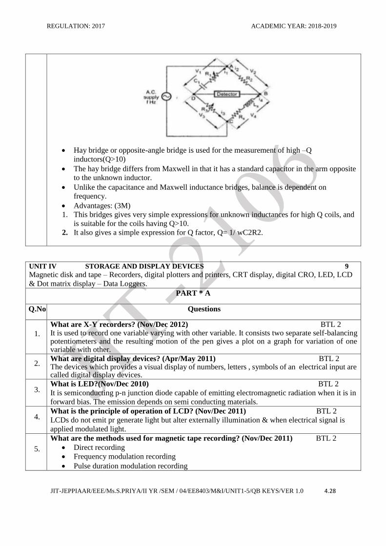
Circuit diagram and explanation(10M)
REGULATION: 2017 ACADEMIC YEAR: 2018-2019
JIT-JEPPIAAR/EEE/Ms.S.PRIYA/II YR /SEM / 04/EE8403/M&I/UNIT1-5/QB KEYS/VER 1.0 4.28
Hay bridge or opposite-angle bridge is used for the measurement of high –Q
inductors(Q>10)
The hay bridge differs from Maxwell in that it has a standard capacitor in the arm opposite
to the unknown inductor.
Unlike the capacitance and Maxwell inductance bridges, balance is dependent on
frequency.
Advantages: (3M)
1. This bridges gives very simple expressions for unknown inductances for high Q coils, and
is suitable for the coils having Q>10.
2. It also gives a simple expression for Q factor, Q= 1/ wC2R2.
UNIT IV STORAGE AND DISPLAY DEVICES 9
Magnetic disk and tape – Recorders, digital plotters and printers, CRT display, digital CRO, LED, LCD
& Dot matrix display – Data Loggers.
PART * A
Q.No. Questions
1.
What are X-Y recorders? (Nov/Dec 2012) BTL 2 It is used to record one variable varying with other variable. It consists two separate self-balancing potentiometers and the resulting motion of the pen gives a plot on a graph for variation of one variable with other.
2. What are digital display devices? (Apr/May 2011) BTL 2 The devices which provides a visual display of numbers, letters , symbols of an electrical input are called digital display devices.
3. What is LED?(Nov/Dec 2010) BTL 2
It is semiconducting p-n junction diode capable of emitting electromagnetic radiation when it is in
forward bias. The emission depends on semi conducting materials.
4. What is the principle of operation of LCD? (Nov/Dec 2011) BTL 2
LCDs do not emit pr generate light but alter externally illumination & when electrical signal is
applied modulated light.
5.
What are the methods used for magnetic tape recording? (Nov/Dec 2011) BTL 2
Direct recording
Frequency modulation recording
Pulse duration modulation recording
REGULATION: 2017 ACADEMIC YEAR: 2018-2019
JIT-JEPPIAAR/EEE/Ms.S.PRIYA/II YR /SEM / 04/EE8403/M&I/UNIT1-5/QB KEYS/VER 1.0 4.29
6.
What are the main parts of CRT? (Nov/Dec 2011) BTL 2
electron gun
deflection system
fluorescent screen
glass tube or envelope
7.
What are the advantages of digital storage oscilloscope? (Nov/Dec 2009) BTL 2
It is easier to operate and has more capability.
The storage time is infinite.
The cursor measurement is possible.
8.
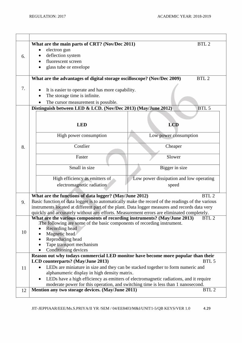
Distinguish between LED & LCD. (Nov/Dec 2013) (May/June 2012) BTL 5
LED
LCD
High power consumption Low power consumption
Costlier Cheaper
Faster Slower
Small in size Bigger in size
High efficiency as emitters of
electromagnetic radiation
Low power dissipation and low operating
speed
9.
What are the functions of data logger? (May/June 2012) BTL 2
Basic function of data logger is to automatically make the record of the readings of the various
instruments located at different part of the plant. Data logger measures and records data very
quickly and accurately without any efforts. Measurement errors are eliminated completely.
10
What are the various components of recording instruments? (May/June 2013) BTL 2 The following are some of the basic components of recording instrument.
Recording head Magnetic head Reproducing head Tape transport mechanism Conditioning devices
11
Reason out why todays commercial LED monitor have become more popular than their
LCD counterparts? (May/June 2013) BTL 5
LEDs are miniature in size and they can be stacked together to form numeric and
alphanumeric display in high density matrix.
LEDs have a high efficiency as emitters of electromagnetic radiations, and it require
moderate power for this operation, and switching time is less than 1 nanosecond.
12 Mention any two storage devices. (May/June 2011) BTL 2
REGULATION: 2017 ACADEMIC YEAR: 2018-2019
JIT-JEPPIAAR/EEE/Ms.S.PRIYA/II YR /SEM / 04/EE8403/M&I/UNIT1-5/QB KEYS/VER 1.0 4.30
Primary magnetic storage Diskettes Hard disks ( bpth fixed and removable) High capacity floppy disks Disk cartridges Magnetic tape
Primary optical storage Compact disk read only memory(CD ROM) Digital Video Disk Read only Memory (DVD ROM) CD Recordable(CD R) CD Rewritable (CD RW) Photo CD
13
Differentiate the functions of printers and plotters.(May/June 2011) BTL 4
The difference is that the former are devices whose purpose is to print letters, numbers and
characters in text readable form, while the latter print diagrams with continuous lines.
14 What is meant by phosphorescence? BTL 2 The property of phosphor material continuing to emit light after its excitation source has been removed is called phosphorescence.
15
What are the different types of printers? BTL 2
Drum wheel printers
Daisy wheel printers
Line printers
Drum printers
Dot-matrix printer
Non-Impact Dot-Matrix Printer
16 Define Transducers. BTL 1
It is device which controls the physical quantity into a proportional electrical signal which is
given as an input to the digital data acquisition system.
17
What is the magnetic principle used in computer data storage? BTL 2 Voltage induced on the tape is proportional to the rate of changes of flux linkages. E α N.dθ/dt
18
Mention the methods of recording. BTL 2 Direct recording F.M recording Pulse duration modulation recording (PDM).
19
A 3-1/2 digit voltmeter is used for measurement. What is its resolution? How it would
display a reading of 12.57 V in 100 V scale? (Apr/May 2017) BTL 4
Resolution:
R= 1/10n
The resolution of a DVM is determined by the m=number of full digit used.
N= 3, R=0.001
Resolution on 100v scale= 0.001*100=0.1
12.57 on 100V= 12.57*0.1
Display as= 1.257
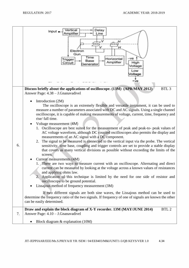
20 Why is a delay line used in the vertical section of an oscilloscope?(Apr/May 2017) BTL 2
The circuit is used to, delay the signal for a period of time in the vertical section of CRT. The
REGULATION: 2017 ACADEMIC YEAR: 2018-2019
JIT-JEPPIAAR/EEE/Ms.S.PRIYA/II YR /SEM / 04/EE8403/M&I/UNIT1-5/QB KEYS/VER 1.0 4.31
input signal is not applied directly to the vertical places because the parts of the signal gets lost, when the delay time not used. Therefore, the input signal is delayed by a period of time.
PART * B
1.
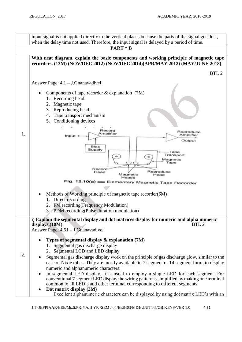
With neat diagram, explain the basic components and working principle of magnetic tape
recorders. (13M) (NOV/DEC 2012) (NOV/DEC 2014)(APR/MAY 2012) (MAY/JUNE 2018)
BTL 2
Answer Page: 4.1 – J.Gnanavadivel
Components of tape recorder & explanation (7M)
1. Recording head
2. Magnetic tape
3. Reproducing head
4. Tape transport mechanism
5. Conditioning devices
Methods of Working principle of magnetic tape recorder(6M)
1. Direct recording
2. FM recording(Frequency Modulation)
3. PDM recording(Pulse duration modulation)
2.
i) Explain the segmental display and dot matrices display for numeric and alpha numeric displays.(10M) BTL 2 Answer Page: 4.51 – J.Gnanavadivel
Types of segmental display & explanation (7M)
1. Segmental gas discharge display
2. Segmental LCD and LED display
Segmental gas discharge display work on the principle of gas discharge glow, similar to the
case of Nixie tubes. They are mostly available in 7 segment or 14 segment form, to display
numeric and alphanumeric characters. In segmental LED display, it is usual to employ a single LED for each segment. For
conventional 7 segment LED display the wiring pattern is simplified by making one terminal common to all LED’s and other terminal corresponding to different segments.
Dot matrix display (3M) Excellent alphanumeric characters can be displayed by using dot matrix LED’s with an
REGULATION: 2017 ACADEMIC YEAR: 2018-2019
JIT-JEPPIAAR/EEE/Ms.S.PRIYA/II YR /SEM / 04/EE8403/M&I/UNIT1-5/QB KEYS/VER 1.0 4.32
LED at each dot location. Commonly used dot matrices for the display of prominent characters are 5x7, 5x8, and 7x9.
ii) Write short notes on data logging. (3M) The data loggers are used to automatically make a record of the readings of instruments located at different parts of the plants. It measures and records data effortlessly as quickly , as often as accurately desired.
3.
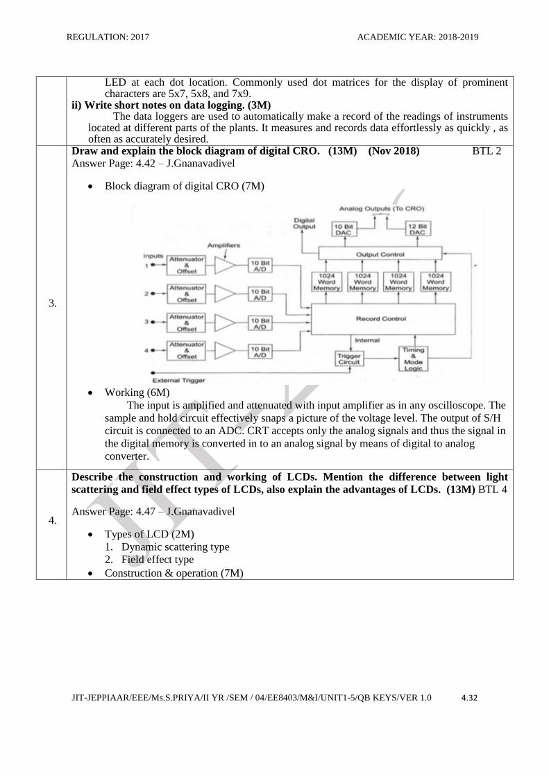
Draw and explain the block diagram of digital CRO. (13M) (Nov 2018) BTL 2 Answer Page: 4.42 – J.Gnanavadivel
Block diagram of digital CRO (7M)
Working (6M)
The input is amplified and attenuated with input amplifier as in any oscilloscope. The
sample and hold circuit effectively snaps a picture of the voltage level. The output of S/H
circuit is connected to an ADC. CRT accepts only the analog signals and thus the signal in
the digital memory is converted in to an analog signal by means of digital to analog
converter.
4.
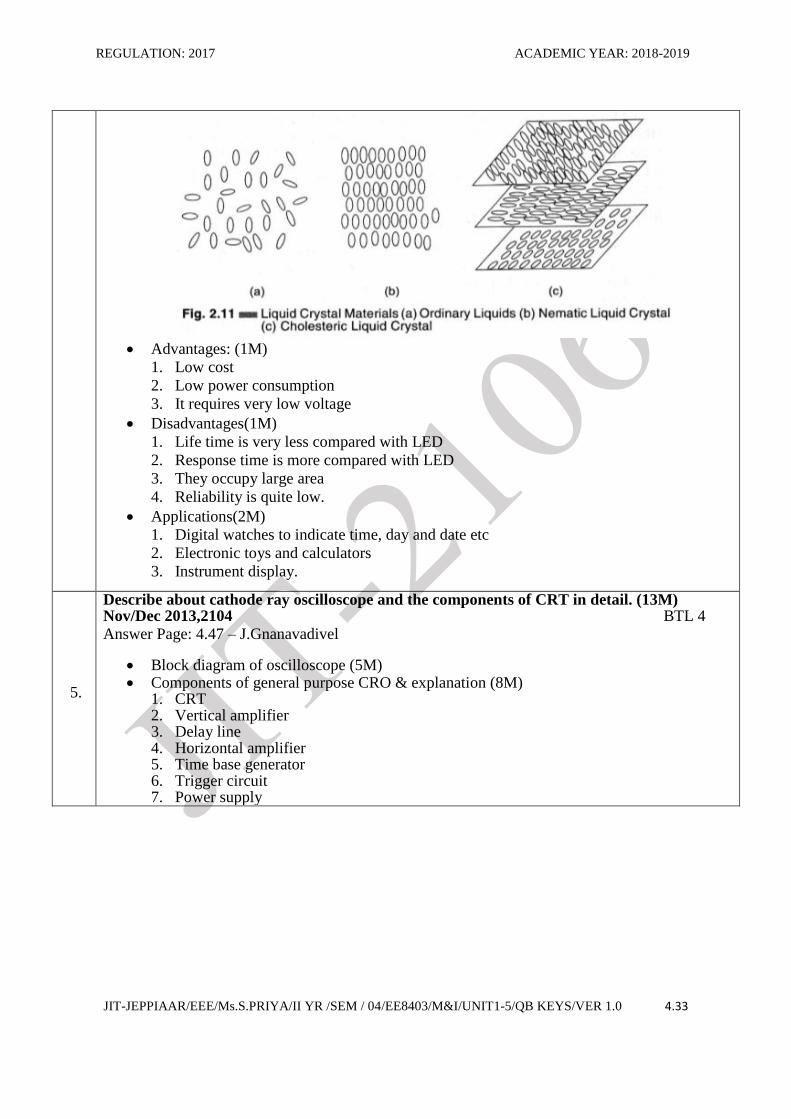
Describe the construction and working of LCDs. Mention the difference between light
scattering and field effect types of LCDs, also explain the advantages of LCDs. (13M) BTL 4
Answer Page: 4.47 – J.Gnanavadivel
Types of LCD (2M)
1. Dynamic scattering type
2. Field effect type
Construction & operation (7M)
REGULATION: 2017 ACADEMIC YEAR: 2018-2019
JIT-JEPPIAAR/EEE/Ms.S.PRIYA/II YR /SEM / 04/EE8403/M&I/UNIT1-5/QB KEYS/VER 1.0 4.33
Advantages: (1M)
1. Low cost
2. Low power consumption
3. It requires very low voltage
Disadvantages(1M)
1. Life time is very less compared with LED
2. Response time is more compared with LED
3. They occupy large area
4. Reliability is quite low.
Applications(2M)
1. Digital watches to indicate time, day and date etc
2. Electronic toys and calculators
3. Instrument display.
5.
Describe about cathode ray oscilloscope and the components of CRT in detail. (13M) Nov/Dec 2013,2104 BTL 4 Answer Page: 4.47 – J.Gnanavadivel
Block diagram of oscilloscope (5M) Components of general purpose CRO & explanation (8M)
1. CRT 2. Vertical amplifier 3. Delay line 4. Horizontal amplifier 5. Time base generator 6. Trigger circuit 7. Power supply
REGULATION: 2017 ACADEMIC YEAR: 2018-2019
JIT-JEPPIAAR/EEE/Ms.S.PRIYA/II YR /SEM / 04/EE8403/M&I/UNIT1-5/QB KEYS/VER 1.0 4.34
6.
Discuss briefly about the applications of oscilloscope. (13M) (APR/MAY 2012) BTL 3
Answer Page: 4.38 – J.Gnanavadivel
Introduction (2M)
The oscilloscope is an extremely flexible and versatile instrument, it can be used to
measure a number of parameters associated with DC and AC signals. Using a single channel
oscilloscope, it is capable of making measurements of voltage, current, time, frequency and
rise/ fall time.
Voltage measurement (4M) 1. Oscilloscope are best suited for the measurement of peak and peak-to- peak values of
AC voltage waveform, although DC coupled oscilloscopes also permits the display and
measurements of an AC signal with a DC component.
2. The signal to be measured is connected to the vertical input via the probe. The vertical
sensitivity, time base, coupling and trigger controls are set to provide a stable display
that covers as many vertical divisions as possible without exceeding the limits of the
screen.
Current measurements (4M)
1. There are two ways to measure current with an oscilloscope. Alternating and direct
current can be measured by looking at the voltage across a known values of resistances
and applying ohms law.
2. Application of this technique is limited by the need for one side of resistor and
oscilloscope to be ground potential.
Lissajous method of frequency measurement (3M)
If two different signals are both sine waves, the Lissajous method can be used to
determine the frequency ratio of the two signals. If frequency of one of signals are known the other
can be easily determined.
7.
Draw and explain the block diagram of X-Y recorder. 13M (MAY/JUNE 2014) BTL 2
Answer Page: 4.10 – J.Gnanavadivel
Block diagram & explanation (10M)
REGULATION: 2017 ACADEMIC YEAR: 2018-2019
JIT-JEPPIAAR/EEE/Ms.S.PRIYA/II YR /SEM / 04/EE8403/M&I/UNIT1-5/QB KEYS/VER 1.0 4.35
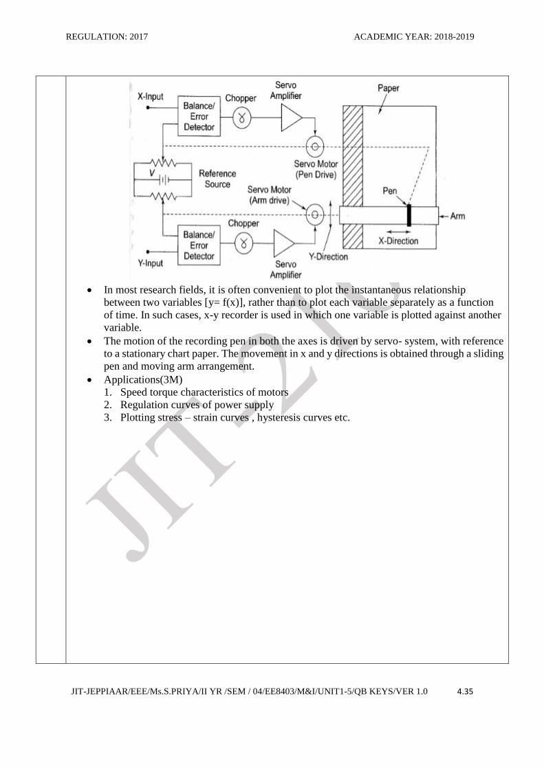
In most research fields, it is often convenient to plot the instantaneous relationship
between two variables [y= f(x)], rather than to plot each variable separately as a function
of time. In such cases, x-y recorder is used in which one variable is plotted against another
variable.
The motion of the recording pen in both the axes is driven by servo- system, with reference
to a stationary chart paper. The movement in x and y directions is obtained through a sliding
pen and moving arm arrangement.
Applications(3M)
1. Speed torque characteristics of motors
2. Regulation curves of power supply
3. Plotting stress – strain curves , hysteresis curves etc.
REGULATION: 2017 ACADEMIC YEAR: 2018-2019
JIT-JEPPIAAR/EEE/Ms.S.PRIYA/II YR /SEM / 04/EE8403/M&I/UNIT1-5/QB KEYS/VER 1.0 4.36
UNIT V TRANSDUCERS AND DATA ACQUISITION SYSTEMS 9 Classification of transducers – Selection of transducers – Resistive, capacitive & inductive Transducers –
Piezoelectric, Hall effect, optical and digital transducers – Elements of data acquisition system – Smart sensors-
Thermal Imagers.
PART * A
Q.No. Questions
1.
What are the basic requirements of a descending order of speed? (Apr/May 2017) BTL 2 Linearity: The input –output characteristics should be linear. Raggedness: It should be capable for with standing overload Residual deformation: There should be no deformations on removal of load after long period of time.
2.
Arrange the following ADC in the descending order of speed. (Apr/May 2017) BTL 3 (a) Integrating type (b) Counter type (c) Successive approximation type (d) Flash type (a) Counter type (b) Integrating type (c) Successive approximation type (d) Flash type
3.
What are the factors to be considered for selection of transducers?(May/June2016) BTL 2
Environment conditions
Operating range Sensitivity
Electrical characteristics Accuracy
4.
List the types of analog to digital converter? (May/June 2016) BTL 4
Flash type ADC
Successive approximation ADC
Counter type ADC
Dual slope ADC
5.
What is transducer? Give example. (Nov/Dec 2015) BTL 2
A transducer is a device that converts one form of energy to another. Usually a transducer
converts a signal in one form of energy to a signal in another.
Example: LVDT, RTD, Thermocouple.
6. What is meant by resolution for analog digital converter? (Nov/Dec 2015) BTL 2
Resolution is defined as the smallest measurable input change.
7. Write the desired properties of thermocouple metals.(Apr/May 2015) BTL 3
It should withstand high temperature
It must possess high melting point.
8.
What are the two ways that the DAS are used to measure and record analog signals?
(Apr/May 2015) BTL 2
Signals may originate from direct measurement of electrical quantities.
Signals may originate from transducers such as transducer or thermocouples.
REGULATION: 2017 ACADEMIC YEAR: 2018-2019
JIT-JEPPIAAR/EEE/Ms.S.PRIYA/II YR /SEM / 04/EE8403/M&I/UNIT1-5/QB KEYS/VER 1.0 4.37
9.
What is an active transducer?(Nov/Dec 2012) BTL 2 An element which produces electrical signal in the form of voltage or current d.c. or a.c. without
using external power, when stimulated by any form of physical quantity is called an active transducer.
10 What do you mean by sensor & transducer?(Apr/May 2011) BTL 2
It is define as devices which produce a measurable response to change in a physical quantity. The transducer is devices which transform the output of a sensor to an electrical o/p.
11
What is the application of thermistor?(May/June 2014) BTL 2
The sensitivity of thermistor is large
High sensitivity & high relativity
Use for thermal conduction measurements..
12
Which elements used in resistances thermometer?(Apr/May 2015) BTL 3
Platinium,
copper,
nickel
13
What is shaft encoder? (Nov/Dec 2010) BTL 2 It’s a rotational displacement transducer which is used to measure the angular motion of a body
about axis of rotation. it works on the principle whose displacement is to measure when rotates.
14 What is R-2Rladder? (Apr/May 2015) BTL 2 For D/A conversion the shunt resistors are used to generate n binary weighted currents. These resistors look like a ladder hence called R-Rladder
15
What is piezo-electric effect? BTL 2
A Piezoelectric material is one in which an electric potential appears across certain surfaces of
the crystals if the dimensions of the crystals are changed by the application of a mechanical force
this potential is produced by the displacement of charges. This effect is reversible. This
phenomenon is known as piezoelectric effect.
16 What is strain gauge? BTL 2
It is a passive transducer which convert the mechanical elongation and compression into change
in resistance.
17 Define gauge factor? BTL 1 It is defined as unit change in resistance for per unit change in length of the strain gauge wire.
18
What is LVDT? List the advantages? BTL 2 It is a passive transducers which is used to measure the linear displacement into electrical signal voltage.
High output High efficiency Low power consumption into electrical signal voltage
19
What are the classifications of encoder? BTL 2
Tachometer transducers
Incremented transducers
Absolute transducers
20
List the types of strain gauge. BTL 3
Bounded strain gauge
Unbounded strain gauge
Metallic strain gauge
Foil type strain gauge
REGULATION: 2017 ACADEMIC YEAR: 2018-2019
JIT-JEPPIAAR/EEE/Ms.S.PRIYA/II YR /SEM / 04/EE8403/M&I/UNIT1-5/QB KEYS/VER 1.0 4.38
Semiconductor strain gauge
PART * B
1.
Explain the binary weighted resistor technique of D/A conversion. (13M) (MAY/JUNE 2014)
BTL 3
Answer Page: 5.92 - J.Gnanavadivel
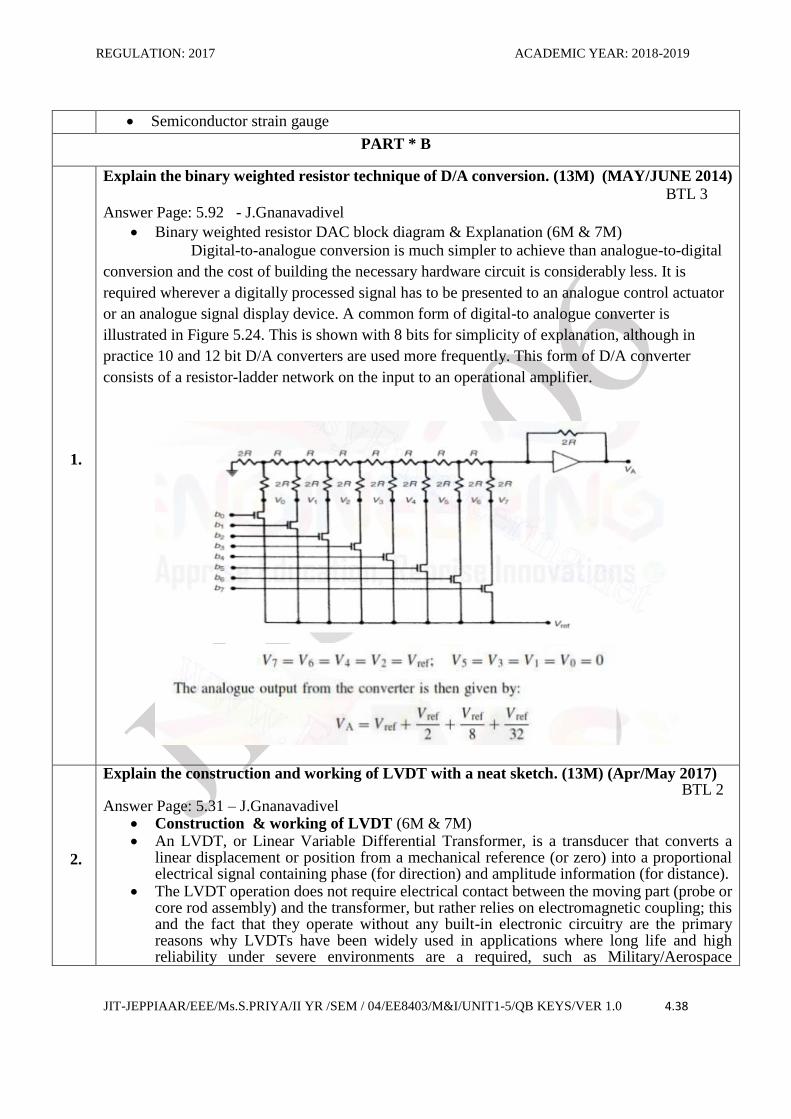
Binary weighted resistor DAC block diagram & Explanation (6M & 7M)
Digital-to-analogue conversion is much simpler to achieve than analogue-to-digital
conversion and the cost of building the necessary hardware circuit is considerably less. It is
required wherever a digitally processed signal has to be presented to an analogue control actuator
or an analogue signal display device. A common form of digital-to analogue converter is
illustrated in Figure 5.24. This is shown with 8 bits for simplicity of explanation, although in
practice 10 and 12 bit D/A converters are used more frequently. This form of D/A converter
consists of a resistor-ladder network on the input to an operational amplifier.
2.
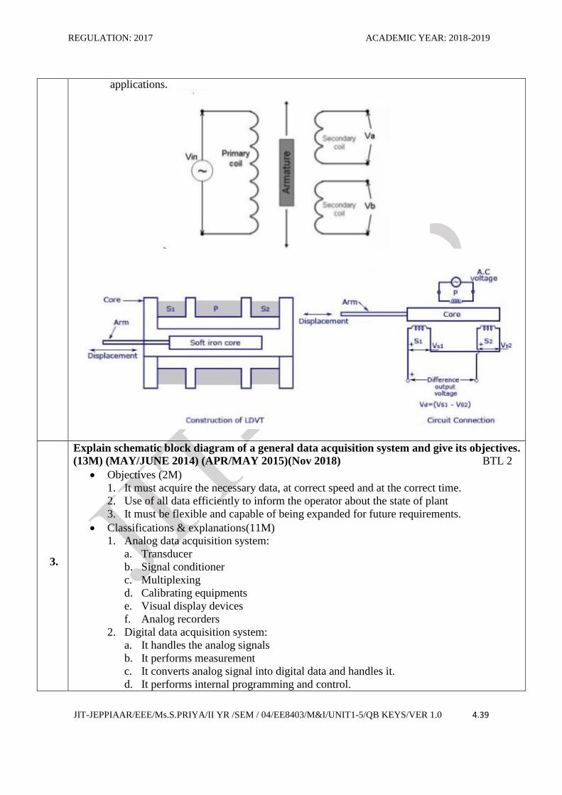
Explain the construction and working of LVDT with a neat sketch. (13M) (Apr/May 2017) BTL 2 Answer Page: 5.31 – J.Gnanavadivel
Construction & working of LVDT (6M & 7M) An LVDT, or Linear Variable Differential Transformer, is a transducer that converts a
linear displacement or position from a mechanical reference (or zero) into a proportional electrical signal containing phase (for direction) and amplitude information (for distance).
The LVDT operation does not require electrical contact between the moving part (probe or core rod assembly) and the transformer, but rather relies on electromagnetic coupling; this and the fact that they operate without any built-in electronic circuitry are the primary reasons why LVDTs have been widely used in applications where long life and high reliability under severe environments are a required, such as Military/Aerospace
REGULATION: 2017 ACADEMIC YEAR: 2018-2019
JIT-JEPPIAAR/EEE/Ms.S.PRIYA/II YR /SEM / 04/EE8403/M&I/UNIT1-5/QB KEYS/VER 1.0 4.39
applications.
3.
Explain schematic block diagram of a general data acquisition system and give its objectives.
(13M) (MAY/JUNE 2014) (APR/MAY 2015)(Nov 2018) BTL 2
Objectives (2M)
1. It must acquire the necessary data, at correct speed and at the correct time.
2. Use of all data efficiently to inform the operator about the state of plant
3. It must be flexible and capable of being expanded for future requirements.
Classifications & explanations(11M)
1. Analog data acquisition system:
a. Transducer
b. Signal conditioner
c. Multiplexing
d. Calibrating equipments
e. Visual display devices
f. Analog recorders
2. Digital data acquisition system:
a. It handles the analog signals
b. It performs measurement
c. It converts analog signal into digital data and handles it.
d. It performs internal programming and control.
REGULATION: 2017 ACADEMIC YEAR: 2018-2019
JIT-JEPPIAAR/EEE/Ms.S.PRIYA/II YR /SEM / 04/EE8403/M&I/UNIT1-5/QB KEYS/VER 1.0 4.40
4.
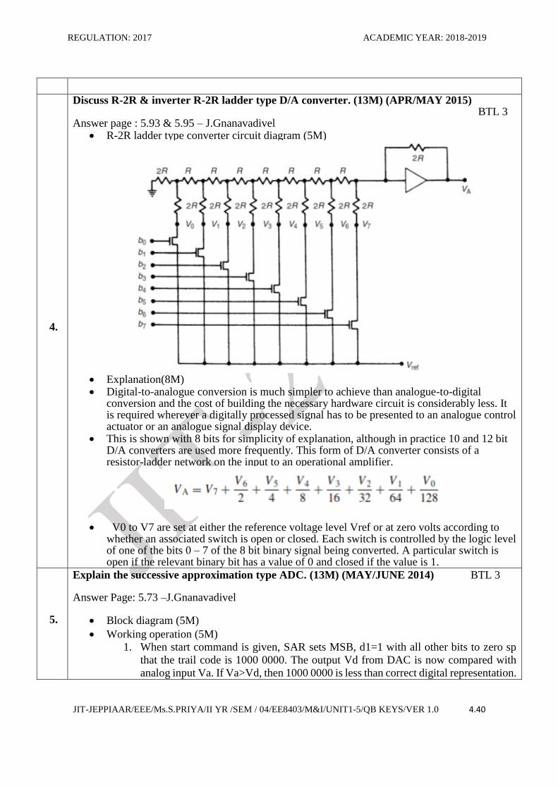
Discuss R-2R & inverter R-2R ladder type D/A converter. (13M) (APR/MAY 2015) BTL 3 Answer page : 5.93 & 5.95 – J.Gnanavadivel
R-2R ladder type converter circuit diagram (5M)
Explanation(8M) Digital-to-analogue conversion is much simpler to achieve than analogue-to-digital
conversion and the cost of building the necessary hardware circuit is considerably less. It is required wherever a digitally processed signal has to be presented to an analogue control actuator or an analogue signal display device.
This is shown with 8 bits for simplicity of explanation, although in practice 10 and 12 bit D/A converters are used more frequently. This form of D/A converter consists of a resistor-ladder network on the input to an operational amplifier.
V0 to V7 are set at either the reference voltage level Vref or at zero volts according to whether an associated switch is open or closed. Each switch is controlled by the logic level of one of the bits 0 – 7 of the 8 bit binary signal being converted. A particular switch is open if the relevant binary bit has a value of 0 and closed if the value is 1.
5.
Explain the successive approximation type ADC. (13M) (MAY/JUNE 2014) BTL 3
Answer Page: 5.73 –J.Gnanavadivel
Block diagram (5M)
Working operation (5M)
1. When start command is given, SAR sets MSB, d1=1 with all other bits to zero sp
that the trail code is 1000 0000. The output Vd from DAC is now compared with
analog input Va. If Va>Vd, then 1000 0000 is less than correct digital representation.
REGULATION: 2017 ACADEMIC YEAR: 2018-2019
JIT-JEPPIAAR/EEE/Ms.S.PRIYA/II YR /SEM / 04/EE8403/M&I/UNIT1-5/QB KEYS/VER 1.0 4.41
2. This procedure is, repeated for all subsequent bits (i.e., from MSB to LSB), one at a
time until all bits positions have been tested.
Advantages: (3M)
1. High resolution
2. It is very versatile
3. High speed
6.
Explain the principle of piezo electric transducers and name any two piezo electric materials.
(13M) (May/JUNE 2009) (APR/MAY 2015) (Nov 2018) BTL 3
Answer Page: 5.45 – J.Gnanavadivel
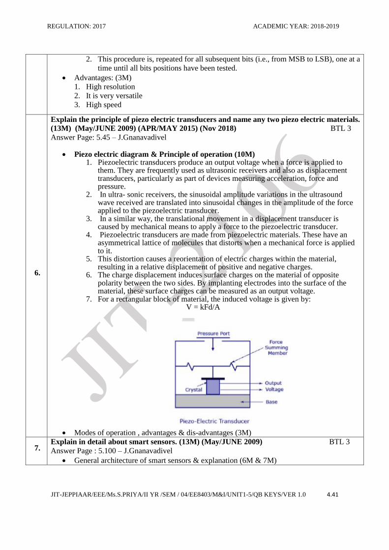
Piezo electric diagram & Principle of operation (10M) 1. Piezoelectric transducers produce an output voltage when a force is applied to
them. They are frequently used as ultrasonic receivers and also as displacement transducers, particularly as part of devices measuring acceleration, force and pressure.
2. In ultra- sonic receivers, the sinusoidal amplitude variations in the ultrasound wave received are translated into sinusoidal changes in the amplitude of the force applied to the piezoelectric transducer.
3. In a similar way, the translational movement in a displacement transducer is caused by mechanical means to apply a force to the piezoelectric transducer.
4. Piezoelectric transducers are made from piezoelectric materials. These have an asymmetrical lattice of molecules that distorts when a mechanical force is applied to it.
5. This distortion causes a reorientation of electric charges within the material, resulting in a relative displacement of positive and negative charges.
6. The charge displacement induces surface charges on the material of opposite polarity between the two sides. By implanting electrodes into the surface of the material, these surface charges can be measured as an output voltage.
7. For a rectangular block of material, the induced voltage is given by: V = kFd/A
Modes of operation , advantages & dis-advantages (3M)
7. Explain in detail about smart sensors. (13M) (May/JUNE 2009) BTL 3
Answer Page : 5.100 – J.Gnanavadivel
General architecture of smart sensors & explanation (6M & 7M)
REGULATION: 2017 ACADEMIC YEAR: 2018-2019
JIT-JEPPIAAR/EEE/Ms.S.PRIYA/II YR /SEM / 04/EE8403/M&I/UNIT1-5/QB KEYS/VER 1.0 4.42
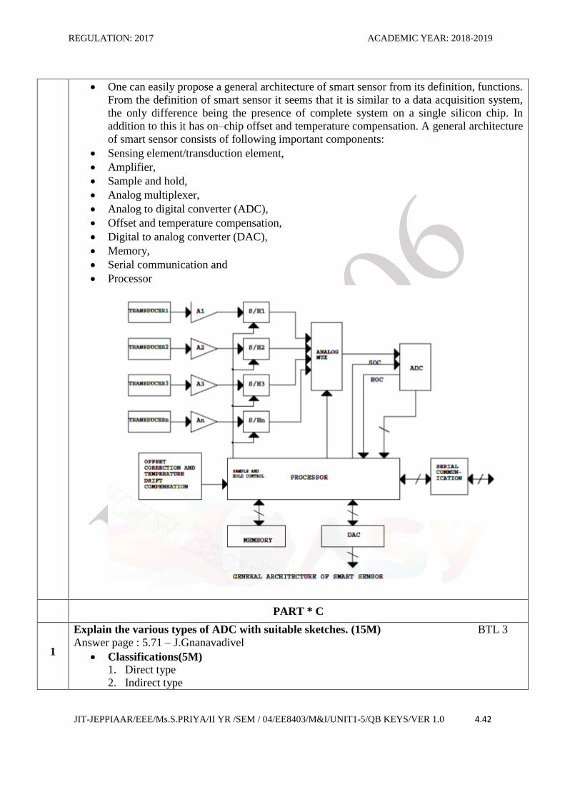
One can easily propose a general architecture of smart sensor from its definition, functions.
From the definition of smart sensor it seems that it is similar to a data acquisition system,
the only difference being the presence of complete system on a single silicon chip. In
addition to this it has on–chip offset and temperature compensation. A general architecture
of smart sensor consists of following important components:
Sensing element/transduction element,
Amplifier,
Sample and hold,
Analog multiplexer,
Analog to digital converter (ADC),
Offset and temperature compensation,
Digital to analog converter (DAC),
Memory,
Serial communication and
Processor
PART * C
1
Explain the various types of ADC with suitable sketches. (15M) BTL 3
Answer page : 5.71 – J.Gnanavadivel
Classifications(5M)
1. Direct type
2. Indirect type
REGULATION: 2017 ACADEMIC YEAR: 2018-2019
JIT-JEPPIAAR/EEE/Ms.S.PRIYA/II YR /SEM / 04/EE8403/M&I/UNIT1-5/QB KEYS/VER 1.0 4.43
Direct types are classified as
1. Flash (comparator) type converter
2. Staircase type converter
3. Tracking or servo converter
4. Successive approximation type converter
Indirect type are classified as
1. Charge balancing analog to digital converter
2. Dual slope analog to digital converter
Explanation of each type (10M)
2
Discuss in detail about(APR/MAY 2015) BTL 4
(i)Optical encoder (5M)
(ii)Resistive encoder(5M)
(iii)Shaft encoder.(5M)
Answer page : 5.56 – J.Gnanavadivel
Optical encoder: (5M)
1. A photo sensor and a light source is placed on the two slides of the sector.
2. The displacement is applied to the sector and therefore changes the amount of light
falling on the photo electric sensor.
3. The pattern of the illuminated sensor then carries the information to the location of the
sector.
Resistive encoder : (5M) 1. In this method a pattern can be used is the resistive electric encoder. Here, the shaded
arears are made up of conducting material and the unshaded areas of insulating material.
2. In this method, sliding contacts are used for making the contacts.
Shaft encoder : (5M)
1. A shaft encoder is a mechanical converter that translates the angular position of the shaft
into digital number. It is equivalent to an analog to digital converter.
2. Another method of conversion is the analog variable into an electrical analog signal and
then converts this into digital signals.
3
Explain different strain gauges with the principle of operation. (15M) (May/JUNE 2009)
BTL 3
Answer page : 5.16 – J.Gnanavadivel
Working principle (5M)
1. A strain gauge is an example of a passive transducer that uses the variation in electrical
resistances in wires to sense the strain produced by a force on the wires.
2. If a metal conductor is stretched or compressed, its resistances changes on account of
the fact that both length and diameter of conductor change.
3. Theory and operating principle of resistance strain gauge derivation (10M)


![newspaper.twinfallspubliclibrary.orgnewspaper.twinfallspubliclibrary.org/files/Times... · f lt S s • ---------------- _ > -0 .2 * |_ _ _ _ _________________ Revives 0] into](https://static.fdocuments.in/doc/165x107/5f46b115f03c85114667dcb8/f-lt-s-s-a-0-2-revives.jpg)


