EE303 Lesson 27: Microwave...
36
EE303 Lesson 27: Microwave Communications
Transcript of EE303 Lesson 27: Microwave...
EE303 Lesson 27:MicrowaveCommunications
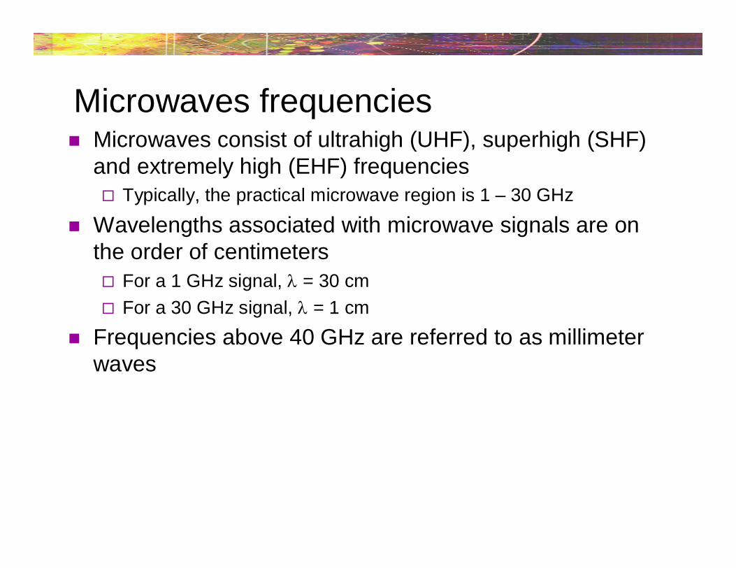
Microwaves frequencies Microwaves consist of ultrahigh (UHF), superhigh (SHF)
and extremely high (EHF) frequencies Typically, the practical microwave region is 1 – 30 GHz
Wavelengths associated with microwave signals are onthe order of centimeters For a 1 GHz signal, = 30 cm
For a 30 GHz signal, = 1 cm
Frequencies above 40 GHz are referred to as millimeterwaves
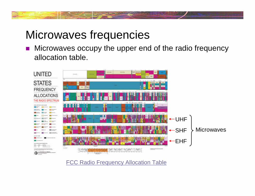
Microwaves frequencies Microwaves occupy the upper end of the radio frequency
allocation table.
FCC Radio Frequency Allocation Table
UHF
SHF
EHF
Microwaves
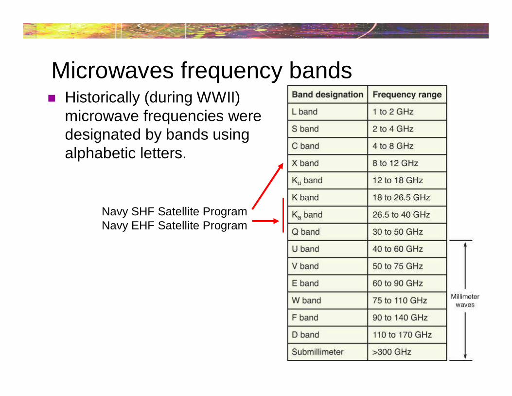
Microwaves frequency bands Historically (during WWII)
microwave frequencies weredesignated by bands usingalphabetic letters.
Navy SHF Satellite ProgramNavy EHF Satellite Program
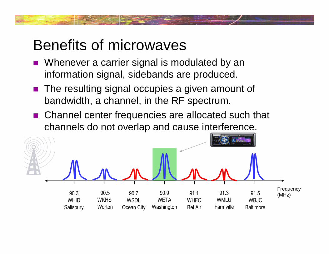
Benefits of microwaves Whenever a carrier signal is modulated by an
information signal, sidebands are produced.
The resulting signal occupies a given amount ofbandwidth, a channel, in the RF spectrum.
Channel center frequencies are allocated such thatchannels do not overlap and cause interference.
90.7WSDL
Ocean City
90.3WHID
Salisbury
Frequency(MHz)90.5
WKHSWorton
91.3WMLU
Farmville
90.9WETA
Washington
91.1WHFCBel Air
91.5WBJC
Baltimore
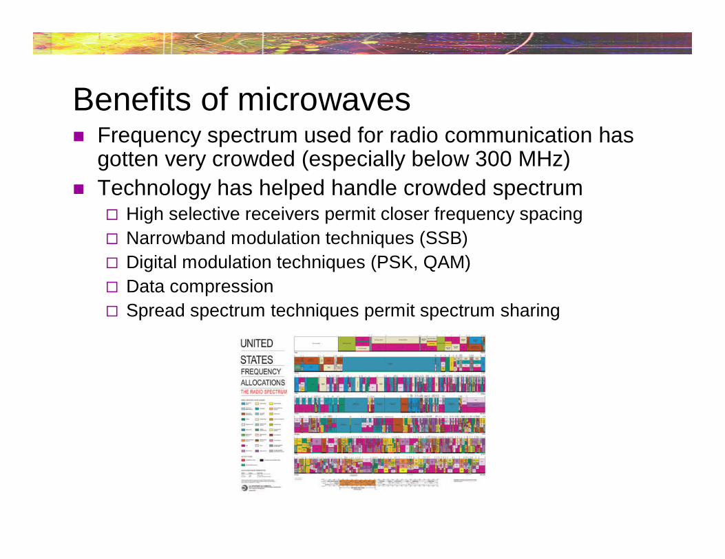
Benefits of microwaves Frequency spectrum used for radio communication has
gotten very crowded (especially below 300 MHz)
Technology has helped handle crowded spectrum High selective receivers permit closer frequency spacing
Narrowband modulation techniques (SSB)
Digital modulation techniques (PSK, QAM)
Data compression
Spread spectrum techniques permit spectrum sharing
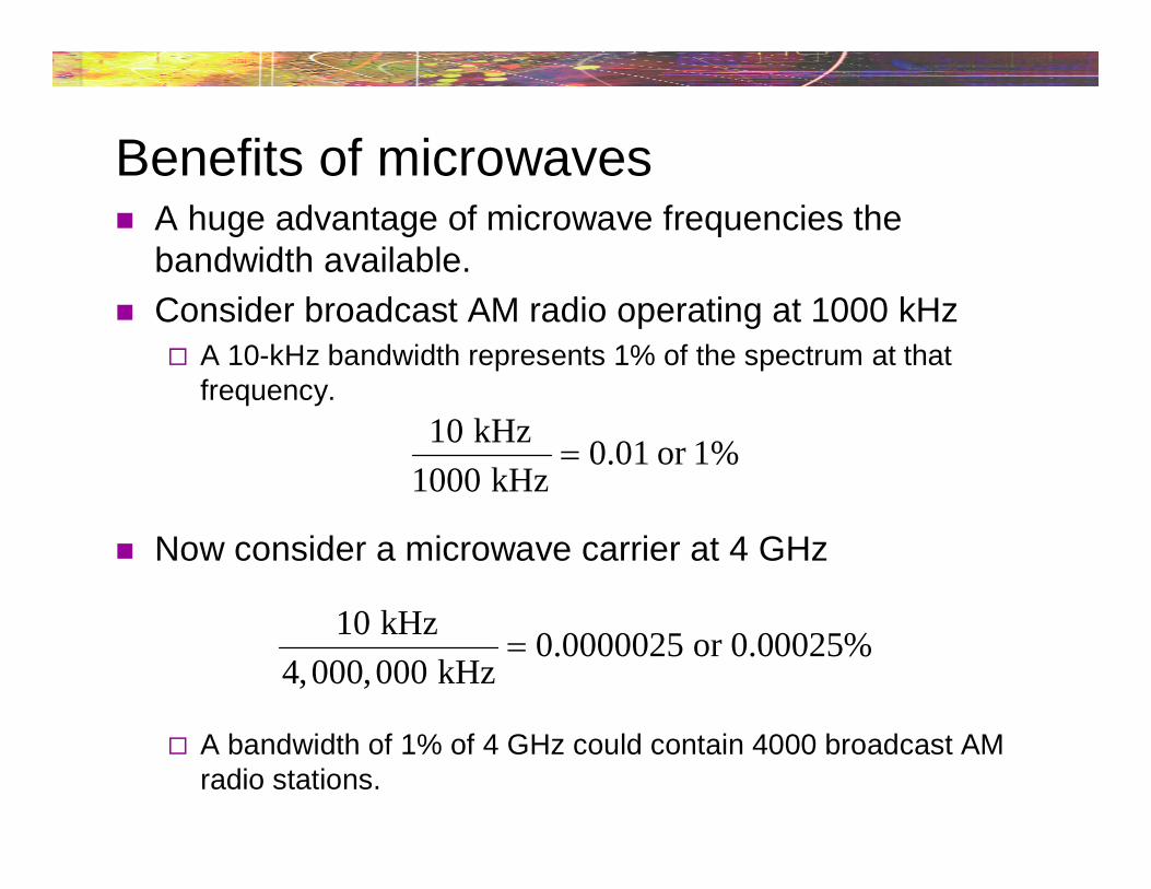
Benefits of microwaves A huge advantage of microwave frequencies the
bandwidth available.
Consider broadcast AM radio operating at 1000 kHz A 10-kHz bandwidth represents 1% of the spectrum at that
frequency.
Now consider a microwave carrier at 4 GHz
A bandwidth of 1% of 4 GHz could contain 4000 broadcast AMradio stations.
10 kHz0.01 or 1%
1000 kHz
10 kHz0.0000025 or 0.00025%
4,000,000 kHz

Benefits of microwaves The huge amount of spectrum available at microwave
frequencies permit the transmission of large amounts ofinformation. Transmission of video (recall analog TV bandwidth = 6 MHz)
High-speed digital
(2332.50 - 2345 MHz)(2320 - 2332.50 MHz)
Disadvantages of microwaves For frequencies below 30 MHz, standard circuit analysis
applies Current-voltage relationships apply (circuit analysis)
This relationship is not usable at microwave frequencies. Analysis must be done in terms of electric and magnetic fields
(wave analysis)
At microwave frequencies, conventional componentsbecome difficult to implement Resistors, capacitors and inductors do not exhibit the same
characteristics at microwave frequencies
Example, short leads on components will add inductance andcapacitance to circuit
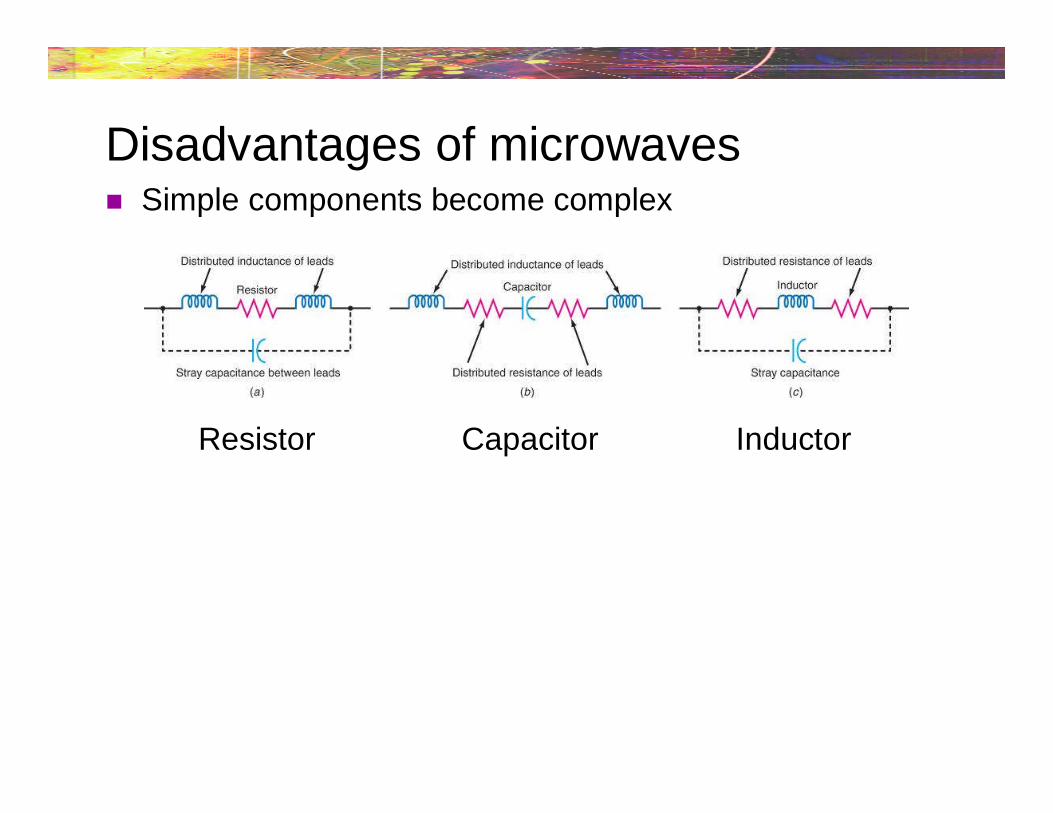
Disadvantages of microwaves Simple components become complex
Resistor Capacitor Inductor
Disadvantages of microwaves Transit time of current carrier (electrons) becomes a
problem at microwave frequencies At low frequencies, this is not a problem
At microwave frequencies, transit time becomes a highpercentage of actual signal period
Conventional silicon transistors don’t operate well at microwavefrequencies.
Microwaves travel in straight lines Communications limited to line-of-sight

Microwave communication systems Microwave transmitters are very similar to their lower
frequency counterparts They contain carrier frequency generators, modulators and
amplifiers
Receivers are superheterodyne types
Transmission lines used for lowerfrequencies have very highattenuation at microwave frequenciesand are unsuitable, except for veryshort runs Waveguides are used instead
Waveguides Long parallel transmission lines radiate electromagnetic
energy while transporting it At microwave frequencies, virtually all energy is radiated and
very little arrives at the antenna
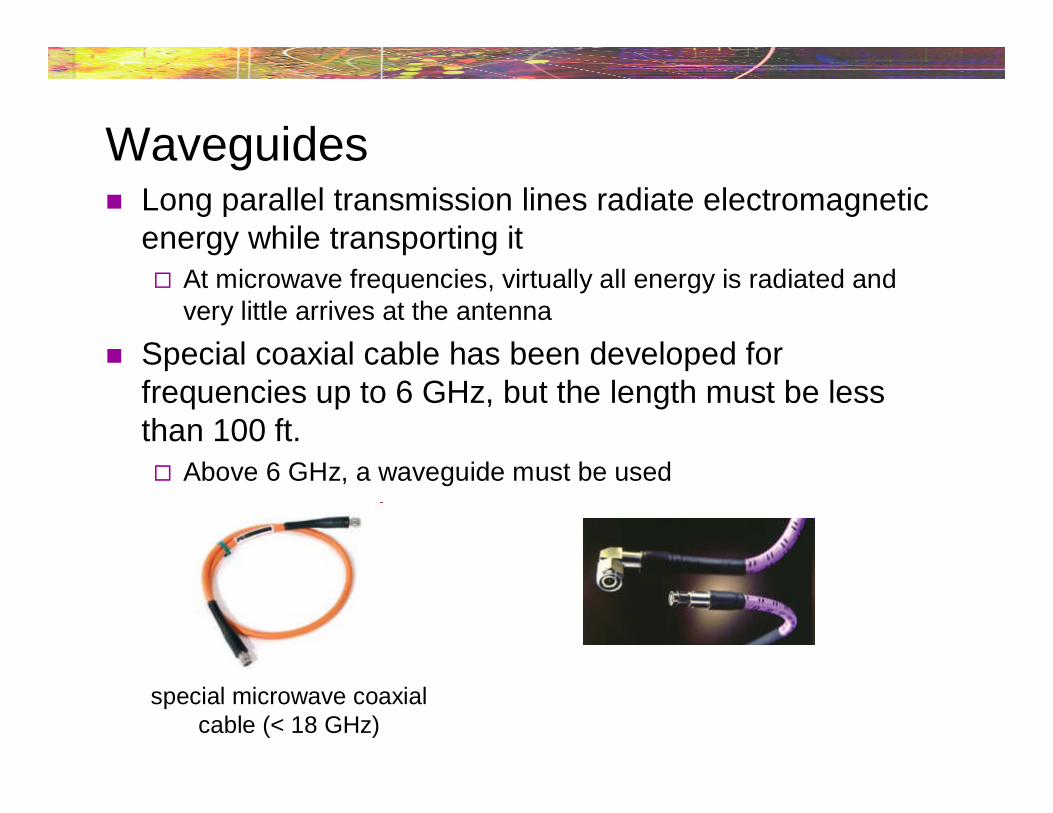
Special coaxial cable has been developed forfrequencies up to 6 GHz, but the length must be lessthan 100 ft. Above 6 GHz, a waveguide must be used
special microwave coaxialcable (< 18 GHz)
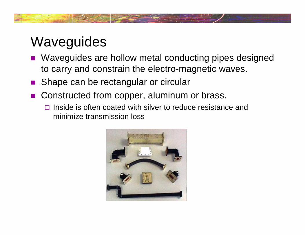
Waveguides Waveguides are hollow metal conducting pipes designed
to carry and constrain the electro-magnetic waves.
Shape can be rectangular or circular
Constructed from copper, aluminum or brass. Inside is often coated with silver to reduce resistance and
minimize transmission loss
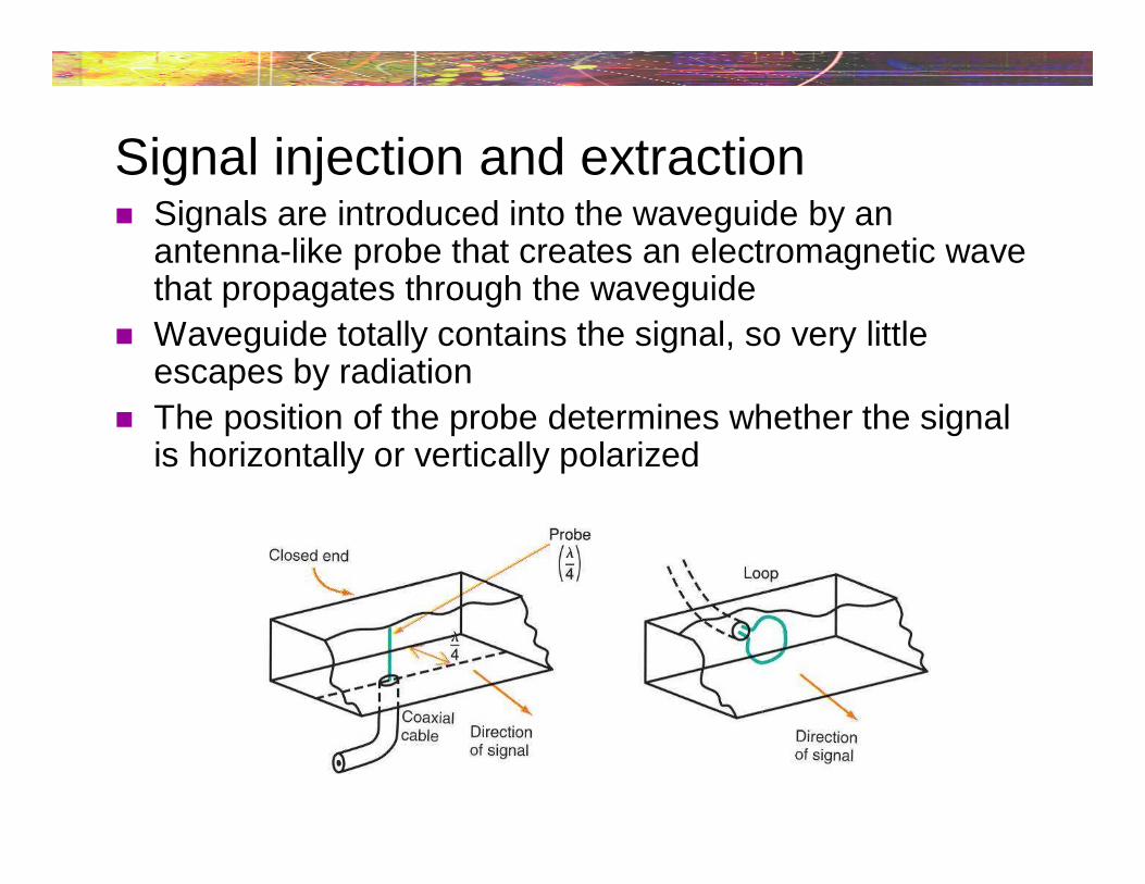
Signal injection and extraction Signals are introduced into the waveguide by an
antenna-like probe that creates an electromagnetic wavethat propagates through the waveguide
Waveguide totally contains the signal, so very littleescapes by radiation
The position of the probe determines whether the signalis horizontally or vertically polarized
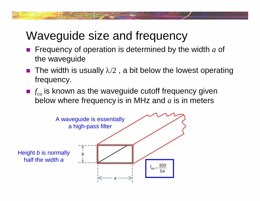
Waveguide size and frequency Frequency of operation is determined by the width a of
the waveguide
The width is usually /2 , a bit below the lowest operatingfrequency.
fco is known as the waveguide cutoff frequency givenbelow where frequency is in MHz and a is in meters
A waveguide is essentiallya high-pass filter
Height b is normallyhalf the width a
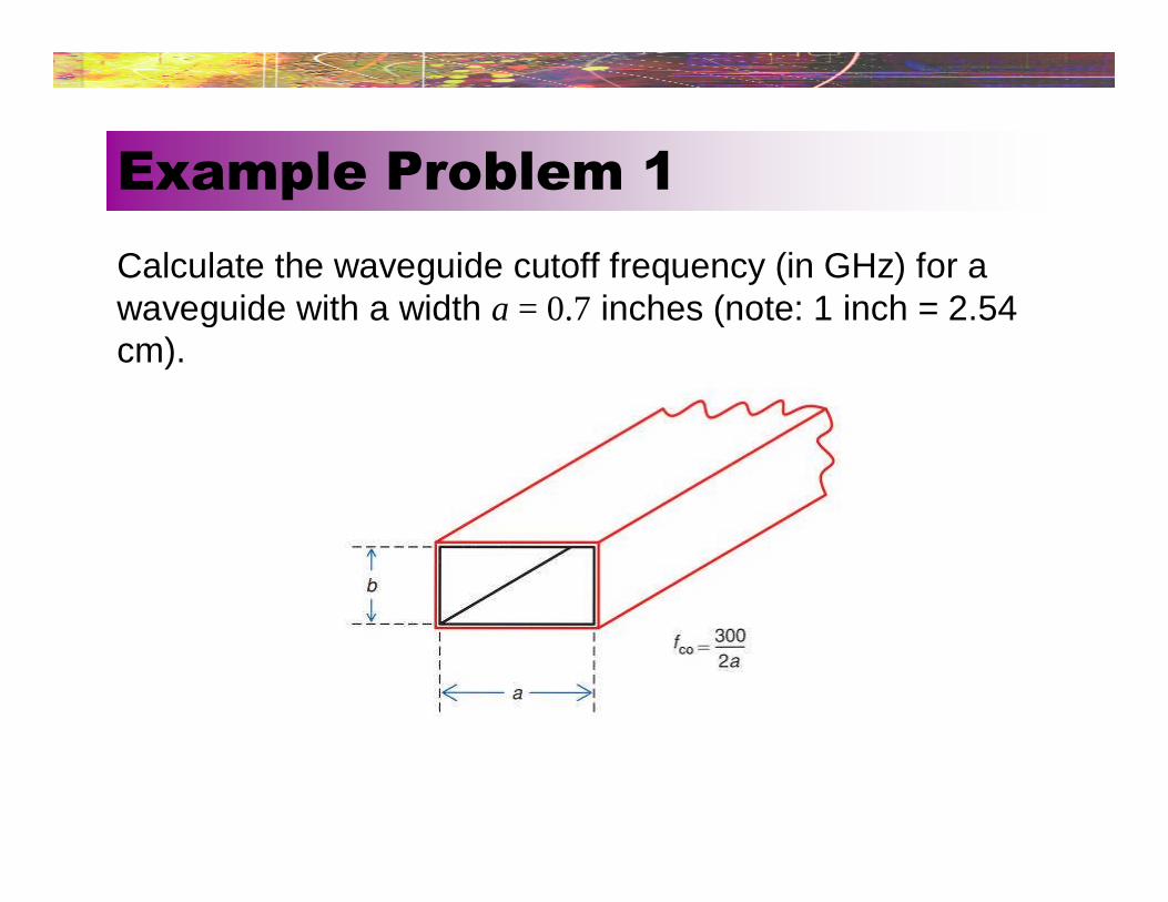
Calculate the waveguide cutoff frequency (in GHz) for awaveguide with a width a = 0.7 inches (note: 1 inch = 2.54cm).
Example Problem 1
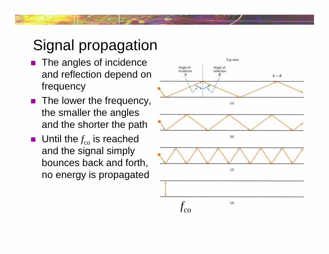
Signal propagation The angles of incidence
and reflection depend onfrequency
The lower the frequency,the smaller the anglesand the shorter the path
Until the fco is reachedand the signal simplybounces back and forth,no energy is propagated
fco

Microwave antennas All antennas discussed previously (half-wave dipole,
quarter-wave dipole, etc) can be used at microwavefrequencies
These antennas will be extremely small. At 5 GHz, half-wave dipole is less than 1 inch long
These antennas also radiate inefficiently
Because of the line-of-site restrictions, high-gain/highlydirective antennas are normally used
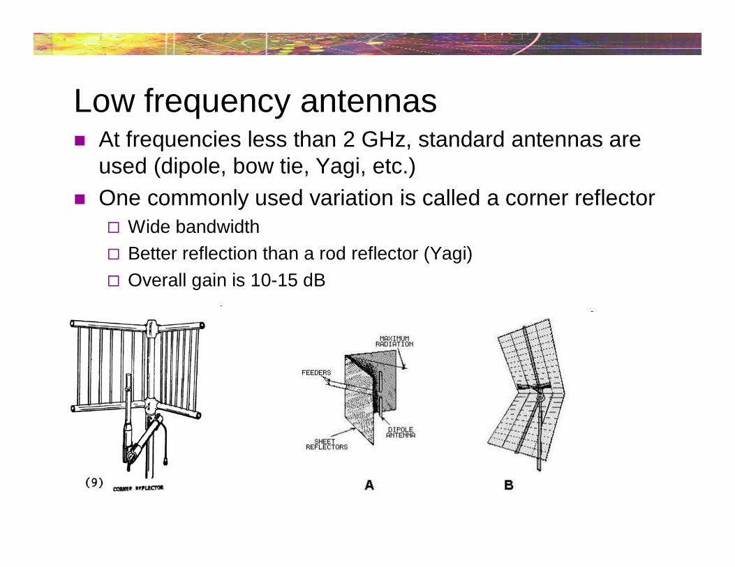
Low frequency antennas At frequencies less than 2 GHz, standard antennas are
used (dipole, bow tie, Yagi, etc.)
One commonly used variation is called a corner reflector Wide bandwidth
Better reflection than a rod reflector (Yagi)
Overall gain is 10-15 dB
Horn antennas Above 6 GHz, signals travel from the transmitter to the
antenna via waveguides
If simply left open at the end, waveguides are inefficientradiators
This can be offset by flaring the end of the waveguide tocreate a horn Horn antennas have excellent gain and directivity
The longer the horn, the greater the gain and directivity
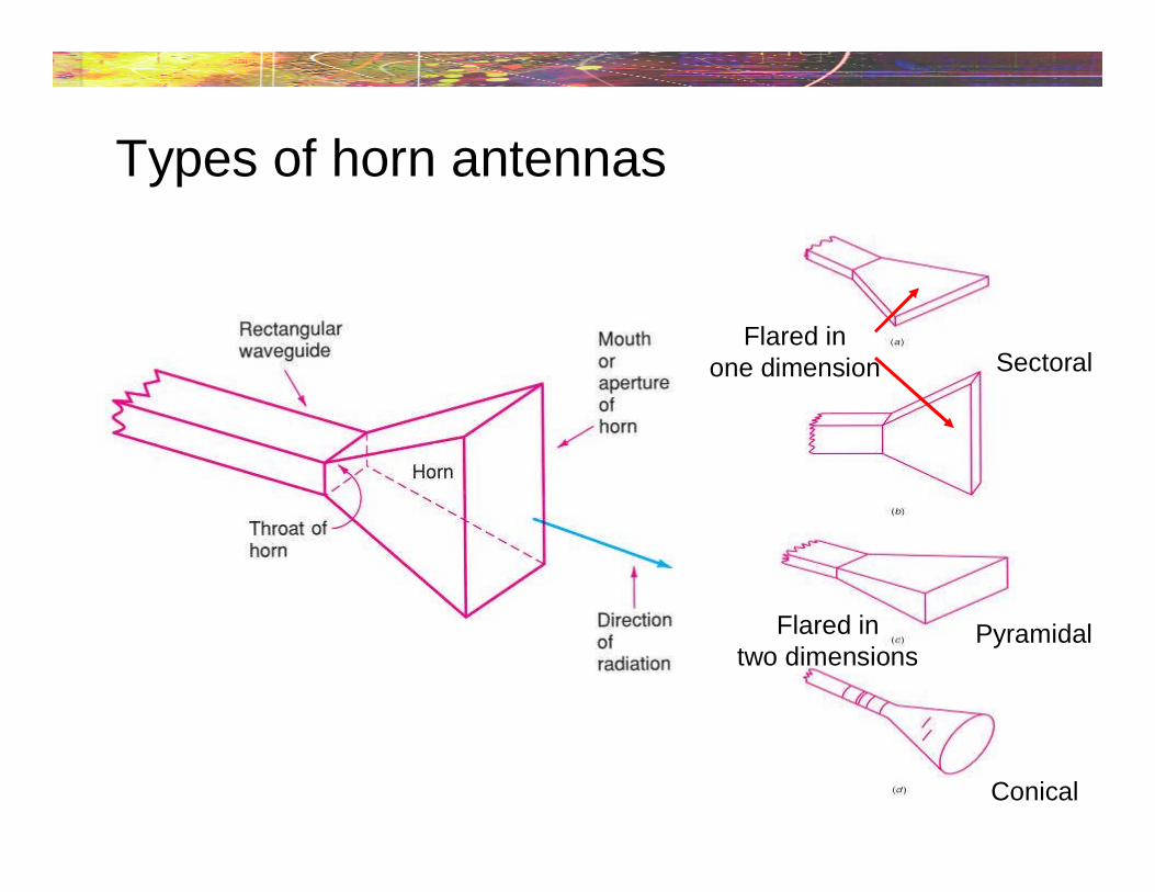
Types of horn antennas
Sectoral
Pyramidal
Conical
Flared inone dimension
Flared intwo dimensions

Horn antennas Gain and directivity are a function of the horn’s dimensions
Most important are length, aperture area and flare angle
The length is usually 2 to 15, at the operating frequency
The greater the aperture area, the higher the gain anddirectivity
Flare angles range from 20° to 60°

Beam width Directivity of an antenna is measured in terms of beam
width, the angle between 3-dB down points.
Typical beam widths for horn antennas are 10º to 60º.
Horizontal (azimuth) beam width Vertical beam width
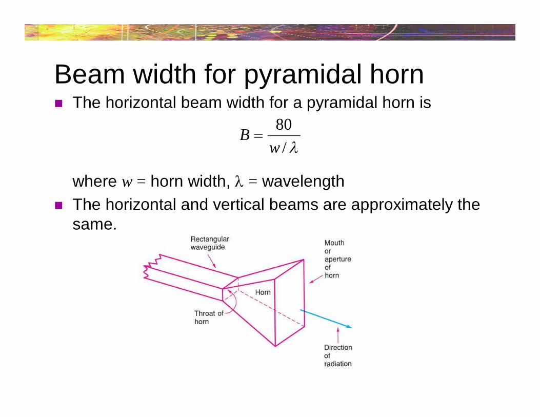
Beam width for pyramidal horn The horizontal beam width for a pyramidal horn is
where w = horn width, = wavelength
The horizontal and vertical beams are approximately thesame.
80
/B
w

Gain for pyramidal horn The power gain of a pyramidal horn is approximately
where A = aperture (m2), K = constant ~ 0.5-0.6 = wavelength
This power gain is relative to a half-wave dipole.
24
KAG
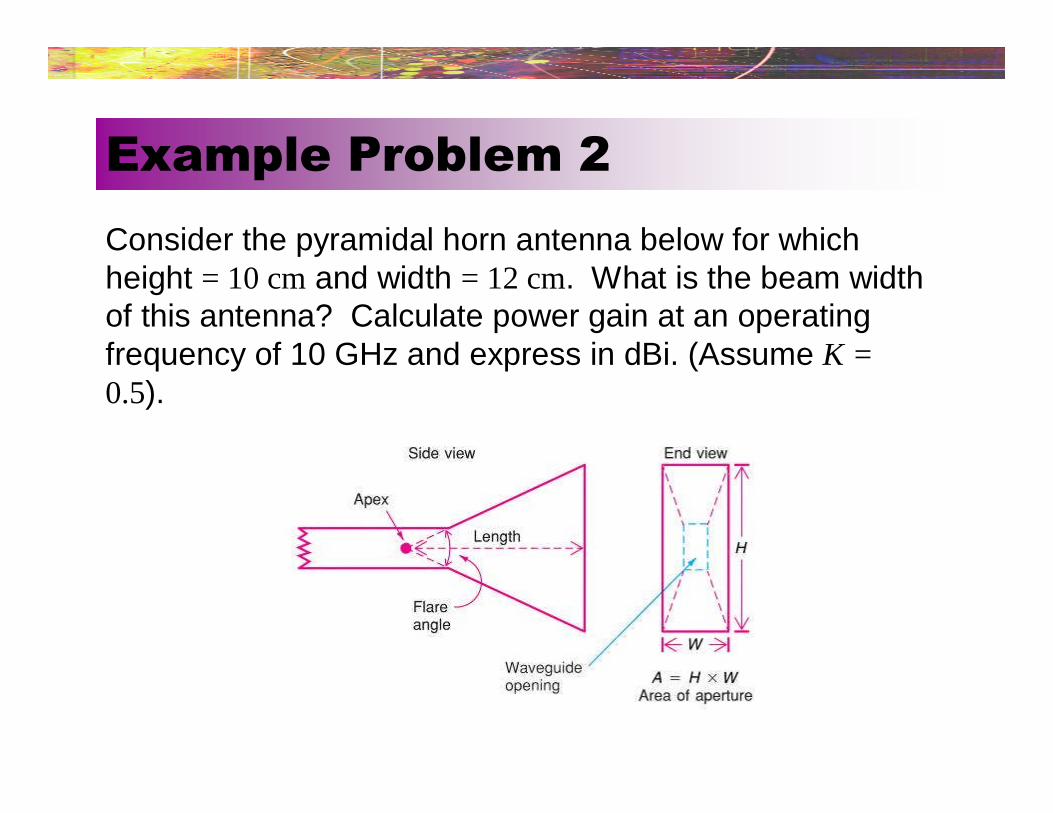
Consider the pyramidal horn antenna below for whichheight = 10 cm and width = 12 cm. What is the beam widthof this antenna? Calculate power gain at an operatingfrequency of 10 GHz and express in dBi. (Assume K =0.5).
Example Problem 2
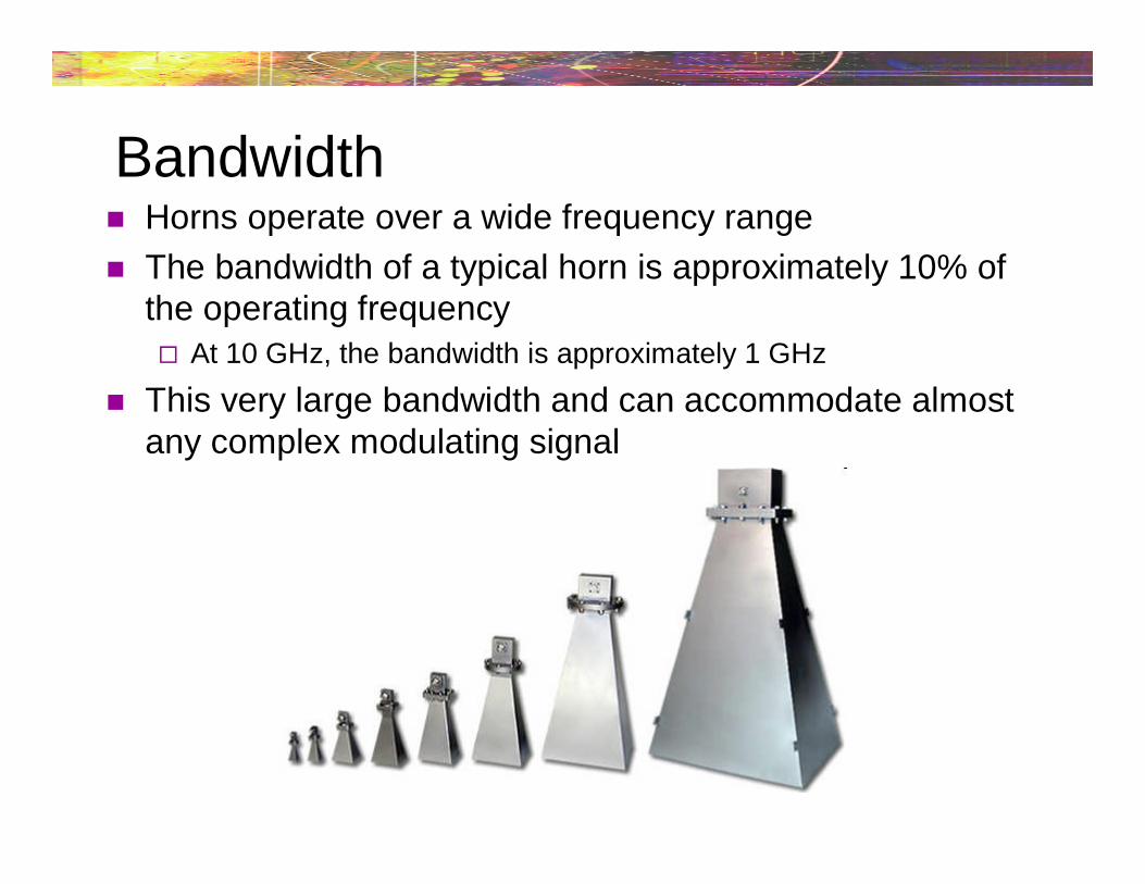
Bandwidth Horns operate over a wide frequency range
The bandwidth of a typical horn is approximately 10% ofthe operating frequency At 10 GHz, the bandwidth is approximately 1 GHz
This very large bandwidth and can accommodate almostany complex modulating signal

The Horn reflector antenna at Bell Telephone Laboratories in Holmdel, New Jersey wasbuilt in 1959 for pioneering work in communication satellites for the NASA ECHO I. The
antenna was 50 feet in length and the entire structure weighed about 18 tons
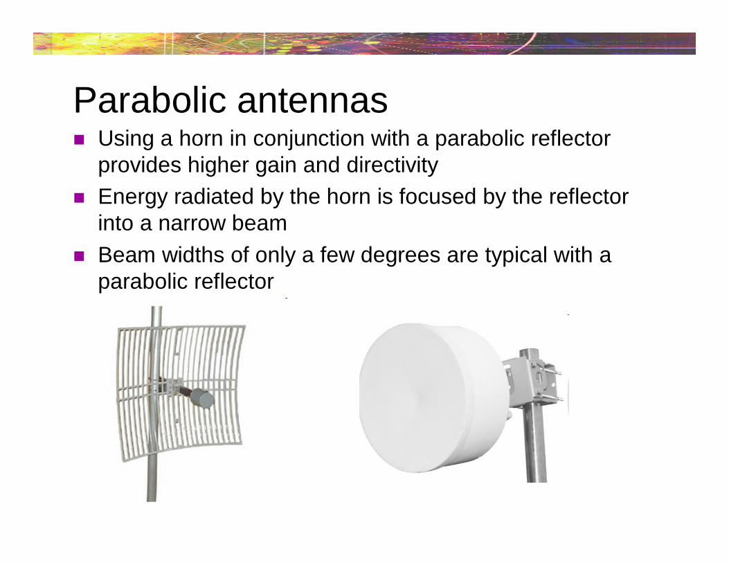
Parabolic antennas Using a horn in conjunction with a parabolic reflector
provides higher gain and directivity
Energy radiated by the horn is focused by the reflectorinto a narrow beam
Beam widths of only a few degrees are typical with aparabolic reflector

Parabolic antennas Can be used for transmit
and receive
Any common antennatype (dipole, etc) can beused with a parabolicreflector
Most parabolic reflectorsare designed so that thediameter is no less than λat the lowest operatingfrequency
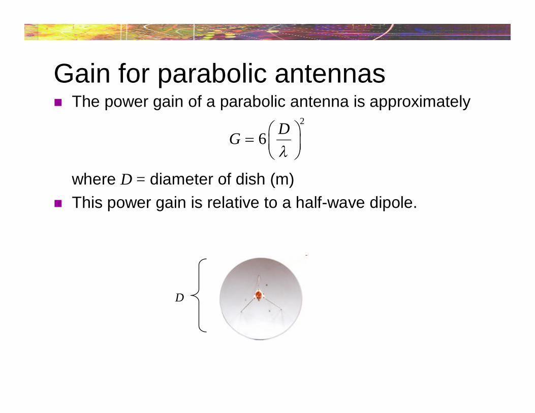
Gain for parabolic antennas The power gain of a parabolic antenna is approximately
where D = diameter of dish (m)
This power gain is relative to a half-wave dipole.
2
6D
G
D
Beam width for parabolic antennas The beam width for a parabolic antenna is
where D = diameter of dish (m)
70
/B
D
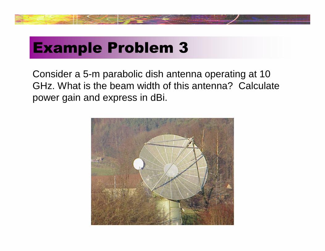
Consider a 5-m parabolic dish antenna operating at 10GHz. What is the beam width of this antenna? Calculatepower gain and express in dBi.
Example Problem 3

Helical antennas Favored because of their simplicity and low cost
Typically use from 6 to 8 turns
Gain is from 12 – 20 dB, with beam widths from 12° - 45°
Widely used in VHF and UHF ranges
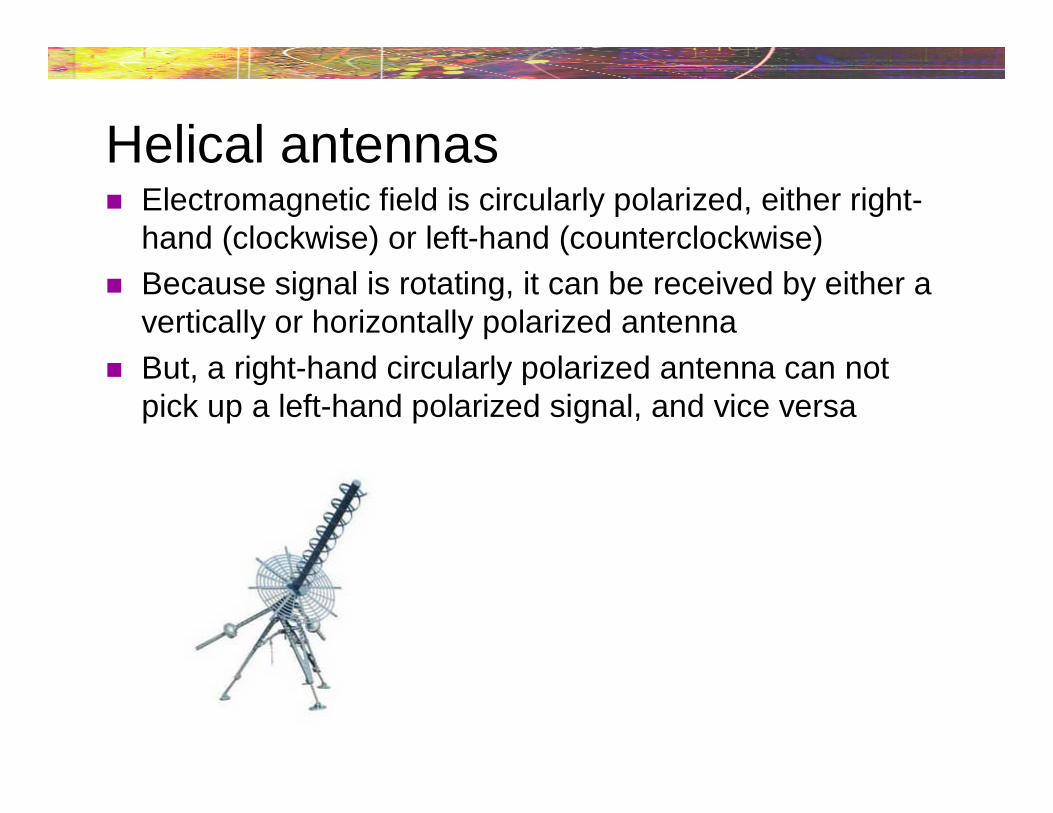
Helical antennas Electromagnetic field is circularly polarized, either right-
hand (clockwise) or left-hand (counterclockwise)
Because signal is rotating, it can be received by either avertically or horizontally polarized antenna
But, a right-hand circularly polarized antenna can notpick up a left-hand polarized signal, and vice versa