Ee201 Notes1 Holey
47
EE 201 SUPPLEMENTARY COURSE NOTES Denard Lynch, P.Eng. Electrical and Computer Engineering University of Saskatchewan © 2000 – 2010 Issue Date: Sep 9, 2010
-
Upload
umamaheswar-reddy -
Category
Documents
-
view
62 -
download
2
Transcript of Ee201 Notes1 Holey
EE 201
SUPPLEMENTARY COURSE NOTES
Denard Lynch, P.Eng. Electrical and Computer Engineering University of Saskatchewan © 2000 – 2010 Issue Date: Sep 9, 2010
Supplementary Course Notes EE201
©Denard Lynch Page1 of 46 Sep , 2010
Magnetic Circuits and Examples
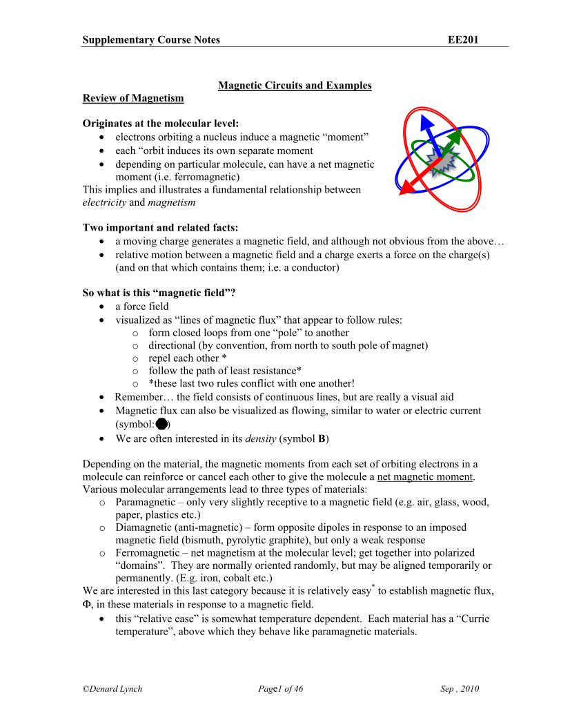
Review of Magnetism Originates at the molecular level:
• electrons orbiting a nucleus induce a magnetic “moment” • each “orbit induces its own separate moment • depending on particular molecule, can have a net magnetic
moment (i.e. ferromagnetic) This implies and illustrates a fundamental relationship between electricity and magnetism Two important and related facts:
• a moving charge generates a magnetic field, and although not obvious from the above… • relative motion between a magnetic field and a charge exerts a force on the charge(s)
(and on that which contains them; i.e. a conductor) So what is this “magnetic field”?
• a force field • visualized as “lines of magnetic flux” that appear to follow rules:
o form closed loops from one “pole” to another o directional (by convention, from north to south pole of magnet) o repel each other * o follow the path of least resistance* o *these last two rules conflict with one another!
• Remember… the field consists of continuous lines, but are really a visual aid • Magnetic flux can also be visualized as flowing, similar to water or electric current
(symbol: !) • We are often interested in its density (symbol B)
Depending on the material, the magnetic moments from each set of orbiting electrons in a molecule can reinforce or cancel each other to give the molecule a net magnetic moment. Various molecular arrangements lead to three types of materials:
o Paramagnetic – only very slightly receptive to a magnetic field (e.g. air, glass, wood, paper, plastics etc.)
o Diamagnetic (anti-magnetic) – form opposite dipoles in response to an imposed magnetic field (bismuth, pyrolytic graphite), but only a weak response
o Ferromagnetic – net magnetism at the molecular level; get together into polarized “domains”. They are normally oriented randomly, but may be aligned temporarily or permanently. (E.g. iron, cobalt etc.)
We are interested in this last category because it is relatively easy* to establish magnetic flux, !, in these materials in response to a magnetic field.
• this “relative ease” is somewhat temperature dependent. Each material has a “Currie temperature”, above which they behave like paramagnetic materials.
Supplementary Course Notes EE201
©Denard Lynch Page2 of 46 Sep , 2010
Why is this (ferromagnetic) ability of interest to us? So we can design “magnetic circuits” to route flux in certain ways and to certain places; the same way we route electric current or hydraulic fluid. We route this to certain places for one of two reasons:
1) The force it can provide a. Speakers, sound reproduction b. Motors, generators c. Door bells, electromagnets
2) its magnetizing effect (i.e. channelizing/routing flux) a. HDDs, magnetic tapes b. Transformers, inductors
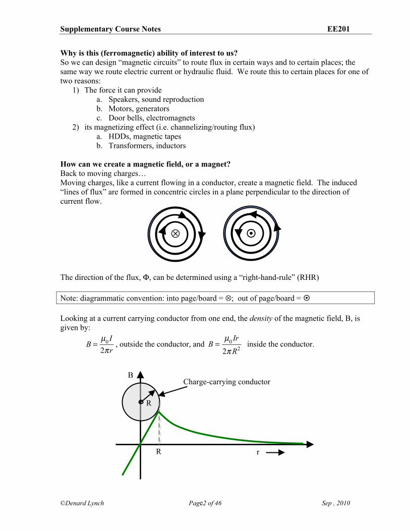
How can we create a magnetic field, or a magnet? Back to moving charges… Moving charges, like a current flowing in a conductor, create a magnetic field. The induced “lines of flux” are formed in concentric circles in a plane perpendicular to the direction of current flow.
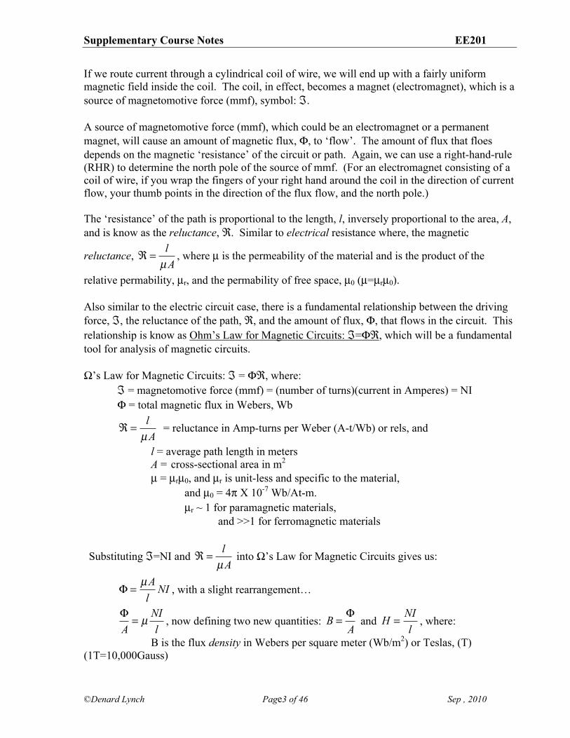
The direction of the flux, !, can be determined using a “right-hand-rule” (RHR) Note: diagrammatic convention: into page/board = "; out of page/board = ! Looking at a current carrying conductor from one end, the density of the magnetic field, B, is given by:
B =
µ0 I2!r
, outside the conductor, and B =
µ0 Ir2!R2
inside the conductor.
B
r R
R
Charge-carrying conductor
" !
Supplementary Course Notes EE201
©Denard Lynch Page3 of 46 Sep , 2010
If we route current through a cylindrical coil of wire, we will end up with a fairly uniform magnetic field inside the coil. The coil, in effect, becomes a magnet (electromagnet), which is a source of magnetomotive force (mmf), symbol: #. A source of magnetomotive force (mmf), which could be an electromagnet or a permanent magnet, will cause an amount of magnetic flux, !, to ‘flow’. The amount of flux that floes depends on the magnetic ‘resistance’ of the circuit or path. Again, we can use a right-hand-rule (RHR) to determine the north pole of the source of mmf. (For an electromagnet consisting of a coil of wire, if you wrap the fingers of your right hand around the coil in the direction of current flow, your thumb points in the direction of the flux flow, and the north pole.) The ‘resistance’ of the path is proportional to the length, l, inversely proportional to the area, A, and is know as the reluctance, $. Similar to electrical resistance where, the magnetic
reluctance, ! =
lµA
, where µ is the permeability of the material and is the product of the
relative permability, µr, and the permability of free space, µ0 (µ=µrµ0). Also similar to the electric circuit case, there is a fundamental relationship between the driving force, #, the reluctance of the path, $, and the amount of flux, !, that flows in the circuit. This relationship is know as Ohm’s Law for Magnetic Circuits: #=!$, which will be a fundamental tool for analysis of magnetic circuits. %’s Law for Magnetic Circuits: # = !$, where: # = magnetomotive force (mmf) = (number of turns)(current in Amperes) = NI ! = total magnetic flux in Webers, Wb
! =
lµA
= reluctance in Amp-turns per Weber (A-t/Wb) or rels, and
l = average path length in meters A = cross-sectional area in m2 µ = µrµ0, and µr is unit-less and specific to the material,
and µ0 = 4& X 10-7 Wb/At-m. µr ~ 1 for paramagnetic materials,
and >>1 for ferromagnetic materials
Substituting #=NI and ! =
lµA
into %’s Law for Magnetic Circuits gives us:
! =
µAl
NI , with a slight rearrangement…
!A= µ NI
l, now defining two new quantities:
B =
!A
and H =
NIl
, where:
B is the flux density in Webers per square meter (Wb/m2) or Teslas, (T) (1T=10,000Gauss)
Supplementary Course Notes EE201
©Denard Lynch Page4 of 46 Sep , 2010
H is the magnetizing force or magnetic field intensity in Amp-turns/m (A-t/m), and substituting these expressions for B and H in the last expression, we have: B = µH
Take the expression for flux density: B =
!A
, or ! = BA. Recalling %’s Law and that the mmf,
# = NI = !$, we can do another manipulation:
NI = !( ) "( ) = BA( ) l
µA#$%
&'(=
Bµ
l = Hl
or NI = Hl, which is a variation of Kirchhoff’s Voltage Law for electric circuits, which can also be stated as: NI = Hl!! , or the sum of the mmf rises around any loop in a magnetic circuit must equal the sum of the magnetizing force drops. This relationship will prove very useful in analyzing magnetic circuits! Let us re-examine the relationship between the flux density, B (which is proportional to !) and the magnetizing force, H (proportional to NI) given as B=µH. µ is the slope of the relationship between B and H and is typically not linear for magnetic materials. It is usually given in graphical form in a “B-H curve”. Hysteresis Hysteresis is a property of magnetic material that causes some residual magnetism to remain in a material after it has been exposed to an external source of mmf. Once a ferromagnetic material is subjected to a magnetic field, the domains align. If the magnetic field is removed, most of the domains will return to (approximately) their original orientation. Dependent on the type of material, some domains may stay oriented in the induced direction, giving the sample some residual magnetism of its own. The amount of (reverse) field strength needed to return the magnetic moment of the sample back to zero is called the coercive force. Magnetic Circuit Problems Magnetic circuit problems faced by a designer are generally one of two types:
1. the NI (mmf) is known, and we need to find the flux, ! or B, or 2. the desired flux, !, or flux density, B, is known and we want to find the required NI.
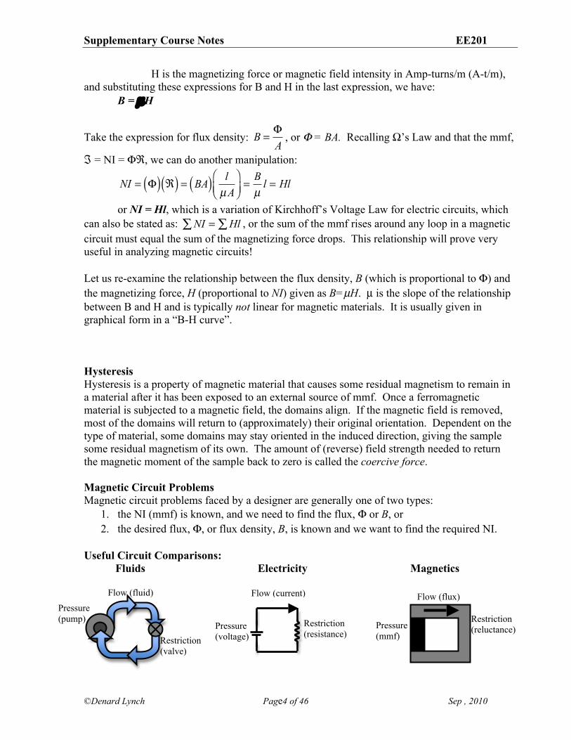
Useful Circuit Comparisons: Fluids Electricity Magnetics
Pressure (pump)
Restriction (valve)
Flow (fluid) Flow (current)
Restriction (resistance)
Pressure (voltage) + Pressure
(mmf)
Flow (flux)
Restriction (reluctance)
S
N
Supplementary Course Notes EE201
©Denard Lynch Page5 of 46 Sep , 2010
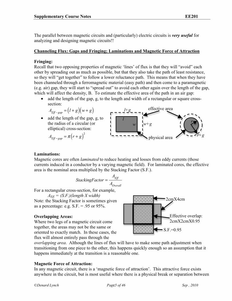
The parallel between magnetic circuits and (particularly) electric circuits is very useful for analyzing and designing magnetic circuits!! Channeling Flux: Gaps and Fringing; Laminations and Magnetic Force of Attraction Fringing: Recall that two opposing properties of magnetic ‘lines’ of flux is that they will “avoid” each other by spreading out as much as possible, but that they also take the path of least resistance, so they will “get together” to follow a lower reluctance path. This means that when they have been channeled through a ferromagnetic material (easy path) and then come to a paramagnetic (e.g. air) gap, they will start to “spread out” to avoid each other again over the length of the gap, which will affect the density, B. To estimate the effective area of the path in an air gap:
• add the length of the gap, g, to the length and width of a rectangular or square cross-section:
AEff !gap = l + g( ) w + g( )
• add the length of the gap, g, to the radius of a circular (or elliptical) cross-section:
AEff !gap = " r + g( )2
Laminations: Magnetic cores are often laminated to reduce heating and losses from eddy currents (those currents induced in a conductor by a varying magnetic field). For laminated cores, the effective area is the nominal area multiplied by the Stacking Factor (S.F.).
StackingFactor =
AEff
AOverall
For a rectangular cross-section, for example, AEff. = (S.F.)(length X width)
Note: the Stacking Factor is sometimes given as a percentage: e.g. S.F. = .95 or 95%. Overlapping Areas: Where two legs of a magnetic circuit come together, the areas may not be the same or oriented to exactly match. In these cases, the flux will almost entirely pass through the overlapping area. Although the lines of flux will have to make some path adjustment when transitioning from one piece to the other, this happens quickly enough so an assumption that it happens immediately at the transition is a reasonable one. Magnetic Force of Attraction: In any magnetic circuit, there is a ‘magnetic force of attraction’. This attractive force exists anywhere in the circuit, but is most useful where there is a physical break or separation between
l w
effective area
physical area
l+g
w+g
r+g
r
2cmX4cm
Effective overlap: 2cmX2cmX0.95
S.F.=0.95
Supplementary Course Notes EE201
©Denard Lynch Page6 of 46 Sep , 2010
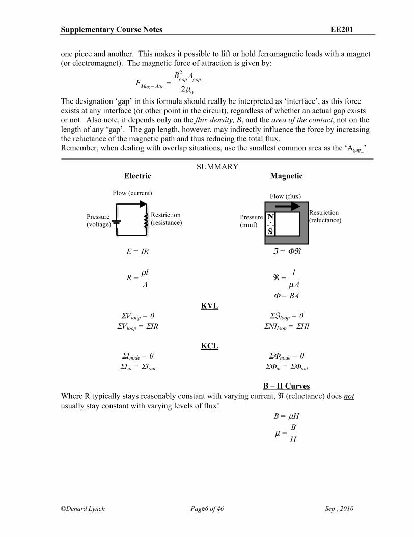
one piece and another. This makes it possible to lift or hold ferromagnetic loads with a magnet (or electromagnet). The magnetic force of attraction is given by:
FMag! Attr =
Bgap2 Agap
2µ0.
The designation ‘gap’ in this formula should really be interpreted as ‘interface’, as this force exists at any interface (or other point in the circuit), regardless of whether an actual gap exists or not. Also note, it depends only on the flux density, B, and the area of the contact, not on the length of any ‘gap’. The gap length, however, may indirectly influence the force by increasing the reluctance of the magnetic path and thus reducing the total flux. Remember, when dealing with overlap situations, use the smallest common area as the ‘Agap_’.
SUMMARY Electric Magnetic E = IR " = !#
R =
!lA
! =
lµA
! = BA KVL $Vloop = 0 $"loop = 0 $Vloop = $IR $NIloop = $Hl KCL $Inode = 0 $!node = 0 $Iin = $Iout $!in = $!out B – H Curves Where R typically stays reasonably constant with varying current, $ (reluctance) does not usually stay constant with varying levels of flux! B = µH
µ =
BH
Flow (current)
Restriction (resistance)
Pressure (voltage) + Pressure
(mmf)
Flow (flux)
Restriction (reluctance)
S
N

Supplementary Course Notes EE201
©Denard Lynch Page7 of 46 Sep , 2010
Some Quick Examples: Fringing: Overlap/Laminations: Hysteresis:
Supplementary Course Notes EE201
©Denard Lynch Page8 of 46 Sep , 2010
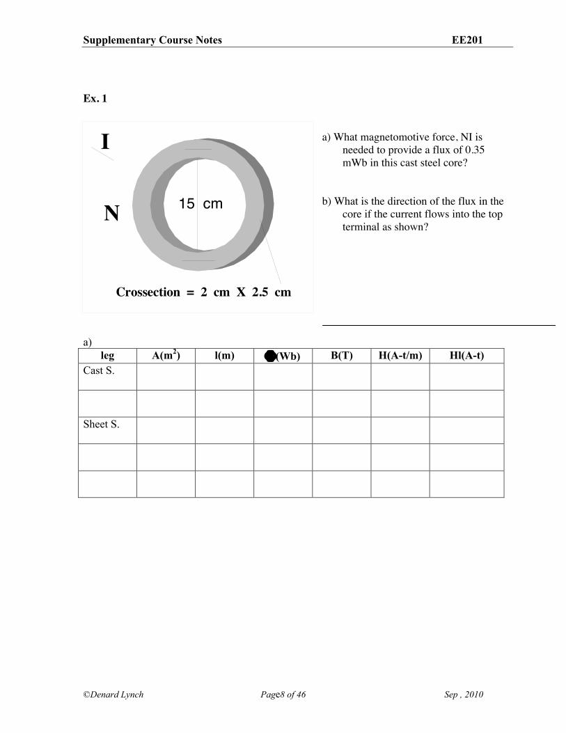
Ex. 1
a) What magnetomotive force, NI is
needed to provide a flux of 0.35 mWb in this cast steel core?
b) What is the direction of the flux in the
core if the current flows into the top terminal as shown?
a)
leg A(m2) l(m) !(Wb) B(T) H(A-t/m) Hl(A-t) Cast S.
Sheet S.
Supplementary Course Notes EE201
©Denard Lynch Page9 of 46 Sep , 2010
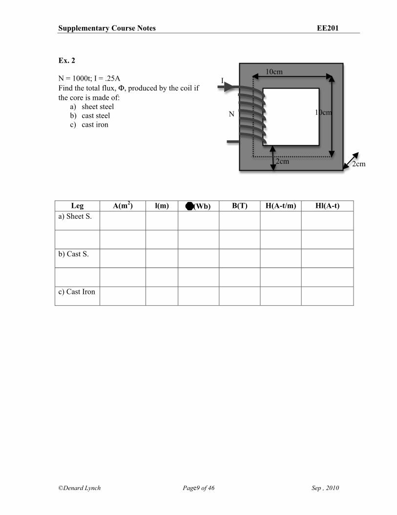
Ex. 2 N = 1000t; I = .25A Find the total flux, !, produced by the coil if the core is made of:
a) sheet steel b) cast steel c) cast iron
Leg A(m2) l(m) !(Wb) B(T) H(A-t/m) Hl(A-t) a) Sheet S.
b) Cast S.
c) Cast Iron
10cm
10cm
2cm 2cm
I
N
Supplementary Course Notes EE201
©Denard Lynch Page10 of 46 Sep , 2010
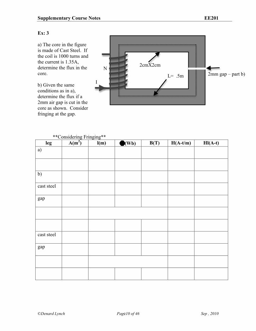
Ex: 3 a) The core in the figure is made of Cast Steel. If the coil is 1000 turns and the current is 1.35A, determine the flux in the core. b) Given the same conditions as in a), determine the flux if a 2mm air gap is cut in the core as shown. Consider fringing at the gap. **Considering Fringing**
leg A(m2) l(m) !(Wb) B(T) H(A-t/m) Hl(A-t) a)
b)
cast steel
gap
cast steel
gap
2mm gap – part b) L= .5m
2cmX2cm
I
N
Supplementary Course Notes EE201
©Denard Lynch Page11 of 46 Sep , 2010
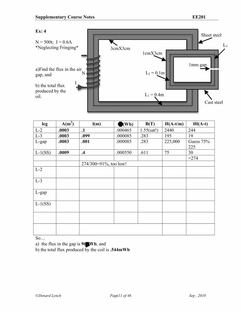
Ex: 4 N = 500t; I = 0.6A *Neglecting Fringing* a)Find the flux in the air gap, and b) the total flux produced by the oil.
leg A(m2) l(m) !(Wb) B(T) H(A-t/m) Hl(A-t) L-2 .0003 .1 .000465 1.55(sat!) 2440 244 L-3 .0003 .099 .000085 .283 195 19 L-gap .0003 .001 .000085 .283 225,000 Guess 75%
225 L-1(SS) .0009 .4 .000550 .611 75 30 =274 274/300=91%, too low! L-2
L-3
L-gap
L-1(SS)
So… a) the flux in the gap is 96µWb, and b) the total flux produced by the coil is .544mWb
I
N
L1 = 0.4m
L2 = 0.1m
1cmX3cm 3cmX3cm
Sheet steel
Cast steel
1mm gap
L3

Supplementary Course Notes EE201
©Denard Lynch Page12 of 46 Sep , 2010
Eg. 5: Consider the magnetic circuit shown in the figure. N1 = N2 = 200t I1 = 8A Stacking Factor for the [laminated] cast steel section is 0.93. The sheet steel sections (with the gap) are solid. Consider fringing effects at the air gap. Find the current, I2, required to establish a flux density, B, of 1.1T in the air gap.
First draw an Electric Equivalent… Note: You can combine the cast segments into one reluctance and also the 2 sheet steel segments into 1 $ because:
i) same material ii) same physical characteristics (dimensions) iii) same flux
Second, make a table, then put in what you know (bold), and finally calculate the rest.
leg A(m2) !(Wb) B(T) H(A-t/m) l(m) Hl(A-t) cast steel
gap
sheet steel
N1
N2
laminatedCastSteel
SheetSteel
I1
I2
2mm gap
3cm
3cm
all x-sections
15cm
15cm
Supplementary Course Notes EE201
©Denard Lynch Page13 of 46 Sep , 2010
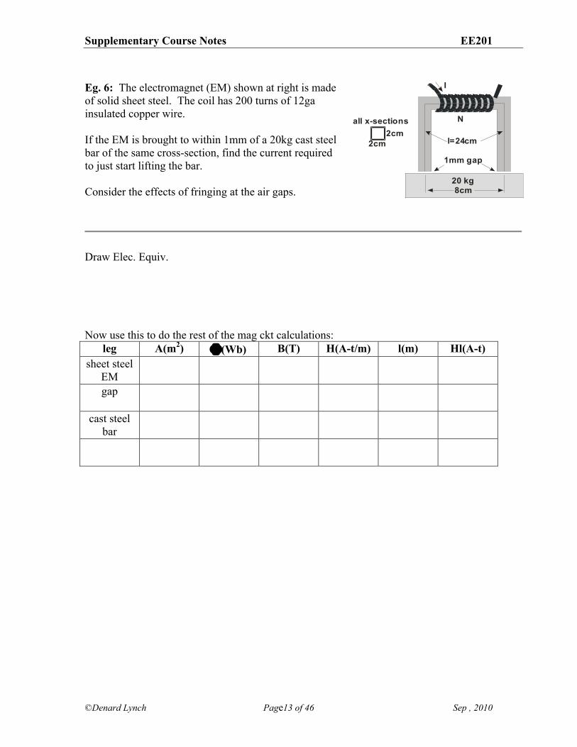
Eg. 6: The electromagnet (EM) shown at right is made of solid sheet steel. The coil has 200 turns of 12ga insulated copper wire. If the EM is brought to within 1mm of a 20kg cast steel bar of the same cross-section, find the current required to just start lifting the bar. Consider the effects of fringing at the air gaps.
Draw Elec. Equiv.
Now use this to do the rest of the mag ckt calculations:
leg A(m2) !(Wb) B(T) H(A-t/m) l(m) Hl(A-t) sheet steel
EM
gap
cast steel bar
2cm
2cm
all x-sections
20 kg
1mm gap
N
I
l=24cm
8cm
Supplementary Course Notes EE201
©Denard Lynch Page14 of 46 Sep , 2010
Force on a moving charge in a magnetic field (Note: see the last page (p4) of this section for a refresher on cross-products if required.) Recall the two sides of the relationship between electricity and magnetism:
i) a moving charge creates a magnetic field, and ii) a magnetic field exerts a force on a a moving charge
We are now going to explore part ii) of this relationship. First, highlight the differences between electric and magnetic fields w.r.t. their effect on a charged particle:
Electric Fields Magnetic Fields
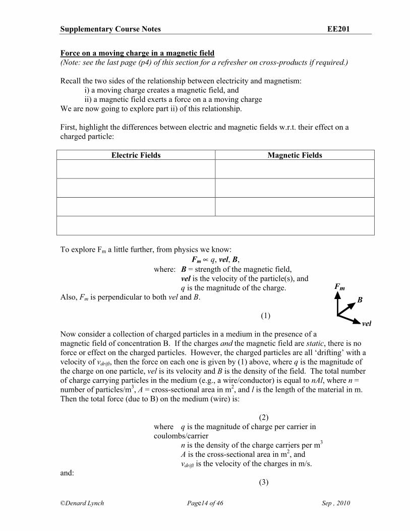
To explore Fm a little further, from physics we know:
Fm ' q, vel, B, where: B = strength of the magnetic field, vel is the velocity of the particle(s), and q is the magnitude of the charge.
Also, Fm is perpendicular to both vel and B.
(1) Now consider a collection of charged particles in a medium in the presence of a magnetic field of concentration B. If the charges and the magnetic field are static, there is no force or effect on the charged particles. However, the charged particles are all ‘drifting’ with a velocity of vdrift, then the force on each one is given by (1) above, where q is the magnitude of the charge on one particle, vel is its velocity and B is the density of the field. The total number of charge carrying particles in the medium (e.g., a wire/conductor) is equal to nAl, where n = number of particles/m3, A = cross-sectional area in m2, and l is the length of the material in m. Then the total force (due to B) on the medium (wire) is:
(2) where q is the magnitude of charge per carrier in coulombs/carrier n is the density of the charge carriers per m3
A is the cross-sectional area in m2, and vdrift is the velocity of the charges in m/s.
and: (3)
FmB
vel
Supplementary Course Notes EE201
©Denard Lynch Page15 of 46 Sep , 2010
(Note: that all units in the expression cancel to leave coulombs/sec, and 1 c/s = 1 ampere.) Substituting (3) into (2) results in the expression for the force on a wire in a field, B:
(4)
where I is the current in A, l is the length of the wire in the filed in meters, m, and B is the magnetic field density in Teslas, T.
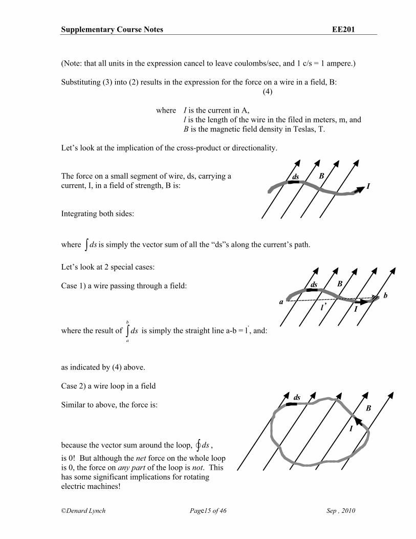
Let’s look at the implication of the cross-product or directionality. The force on a small segment of wire, ds, carrying a current, I, in a field of strength, B is:
Integrating both sides:
where ds! is simply the vector sum of all the “ds”s along the current’s path. Let’s look at 2 special cases: Case 1) a wire passing through a field:
where the result of dsa
b
! is simply the straight line a-b = l’, and:
as indicated by (4) above. Case 2) a wire loop in a field Similar to above, the force is:
because the vector sum around the loop, ds!! ,
is 0! But although the net force on the whole loop is 0, the force on any part of the loop is not. This has some significant implications for rotating electric machines!
ds BI
ds B
Ia
bl’
dsB
I
Supplementary Course Notes EE201
©Denard Lynch Page16 of 46 Sep , 2010
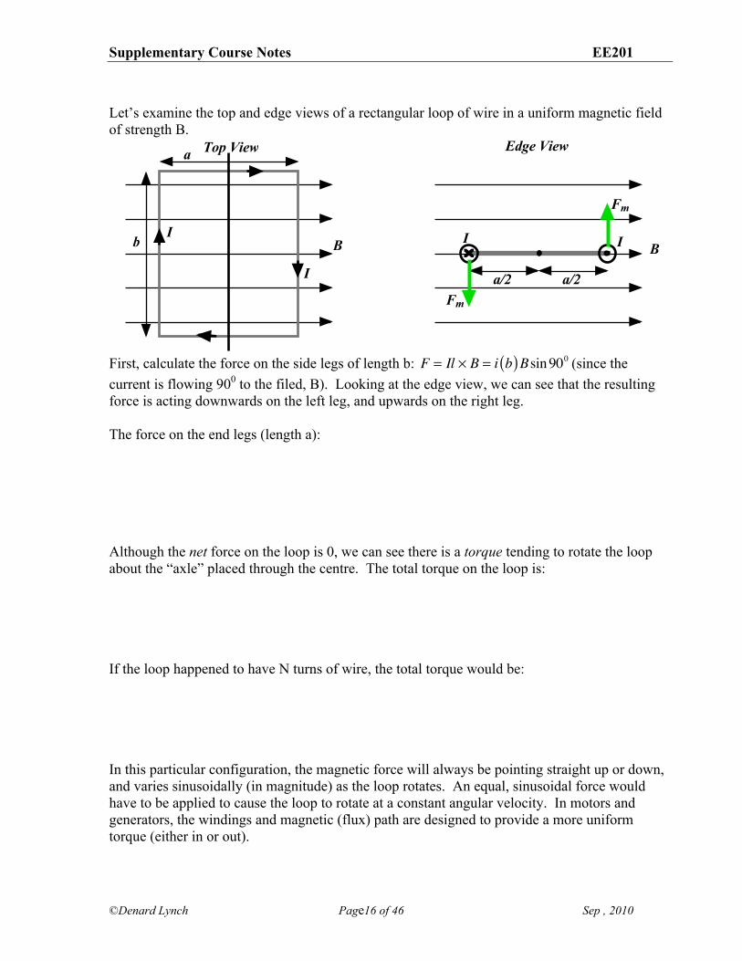
Let’s examine the top and edge views of a rectangular loop of wire in a uniform magnetic field of strength B.
First, calculate the force on the side legs of length b: F = Il ! B = i b( )Bsin900 (since the current is flowing 900 to the filed, B). Looking at the edge view, we can see that the resulting force is acting downwards on the left leg, and upwards on the right leg. The force on the end legs (length a): Although the net force on the loop is 0, we can see there is a torque tending to rotate the loop about the “axle” placed through the centre. The total torque on the loop is: If the loop happened to have N turns of wire, the total torque would be:
In this particular configuration, the magnetic force will always be pointing straight up or down, and varies sinusoidally (in magnitude) as the loop rotates. An equal, sinusoidal force would have to be applied to cause the loop to rotate at a constant angular velocity. In motors and generators, the windings and magnetic (flux) path are designed to provide a more uniform torque (either in or out).
Top View Edge View
B B
a
bI
I
I I
Fm
Fm
a/2 a/2
Supplementary Course Notes EE201
©Denard Lynch Page17 of 46 Sep , 2010
A quick review of cross products: Take an example of a cross-product expression: F = Il X B. It is also correct, and more convenient, to think of the expression as: Il X B = F. In this form, we can think of the cross-product operation as:
(first vector) X (second vector) = (resultant vector) e.g. Il X B = F
RHR 1 (thumb) X 2 (index finger) = 3 (second finger) The Right Hand Rule (RHR) gives the general direction of the resultant given the direction of the input vectors. Mathematically, the cross product expression may be expressed as:
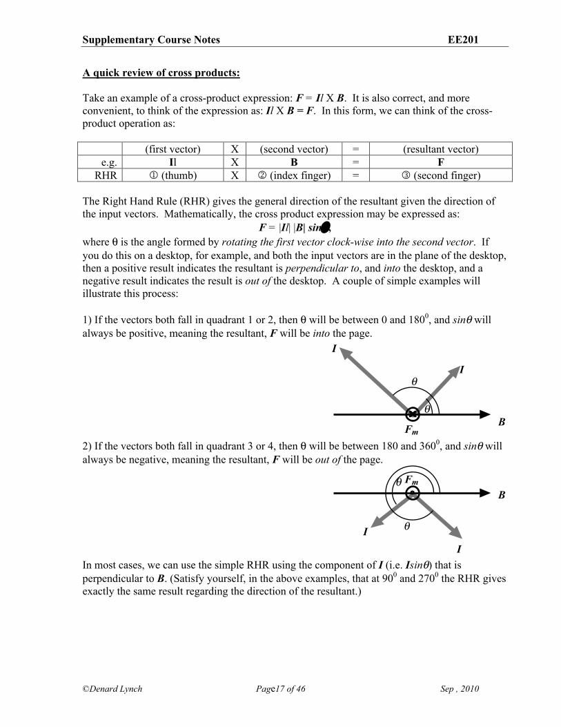
F = |Il| |B| sin% , where ( is the angle formed by rotating the first vector clock-wise into the second vector. If you do this on a desktop, for example, and both the input vectors are in the plane of the desktop, then a positive result indicates the resultant is perpendicular to, and into the desktop, and a negative result indicates the result is out of the desktop. A couple of simple examples will illustrate this process: 1) If the vectors both fall in quadrant 1 or 2, then ( will be between 0 and 1800, and sin% will always be positive, meaning the resultant, F will be into the page.
2) If the vectors both fall in quadrant 3 or 4, then ( will be between 180 and 3600, and sin% will always be negative, meaning the resultant, F will be out of the page.
In most cases, we can use the simple RHR using the component of I (i.e. Isin%) that is perpendicular to B. (Satisfy yourself, in the above examples, that at 900 and 2700 the RHR gives exactly the same result regarding the direction of the resultant.)
B
I
I
Fm
!
!
II
BFm!
!
Supplementary Course Notes EE201
©Denard Lynch Page18 of 46 Sep , 2010
Faraday’s/Lenz’s Laws of Electromagnetic Induction and Motional emf Faraday’s Law: , where !m = total “flux linkages” =
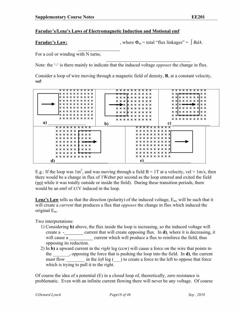
BdA! . For a coil or winding with N turns, Note: the ‘-‘ is there mainly to indicate that the induced voltage opposes the change in flux. Consider a loop of wire moving through a magnetic field of density, B, at a constant velocity, vel:
a) ________________
b) _________________
c) ________________
d) ______________________
e)____________________
E.g.: If the loop was 1m2, and was moving through a field B = 1T at a velocity, vel = 1m/s, then there would be a change in flux of 1Weber per second as the loop entered and exited the field (not while it was totally outside or inside the field). During these transition periods, there would be an emf of ±1V induced in the loop. Lenz’s Law tells us that the direction (polarity) of the induced voltage, Em, will be such that it will create a current that produces a flux that opposes the change in flux which induced the original Em. Two interpretations:
1) Considering b) above, the flux inside the loop is increasing, so the induced voltage will create a -________ current that will create opposing flux. In d), where it is decreasing, it will cause a __________ current which will produce a flux to reinforce the field, thus opposing its reduction.
2) In b) a upward current in the right leg (ccw) will cause a force on the wire that points to the _______, opposing the force that is pushing the loop into the field. In d), the current must flow ________ in the left leg (___) to create a force to the left to oppose that force which is trying to pull it to the right.
Of course the idea of a potential (E) in a closed loop of, theoretically, zero resistance is problematic. Even with an infinite current flowing there will never be any voltage. Of course
Supplementary Course Notes EE201
©Denard Lynch Page19 of 46 Sep , 2010
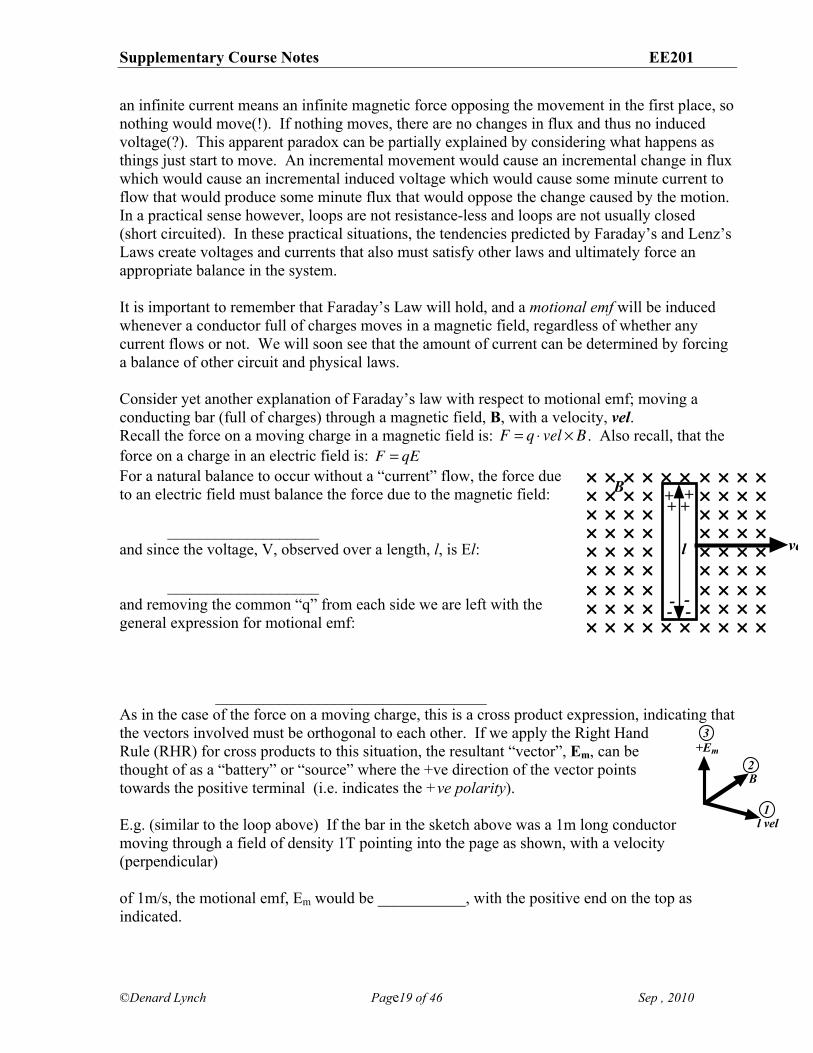
an infinite current means an infinite magnetic force opposing the movement in the first place, so nothing would move(!). If nothing moves, there are no changes in flux and thus no induced voltage(?). This apparent paradox can be partially explained by considering what happens as things just start to move. An incremental movement would cause an incremental change in flux which would cause an incremental induced voltage which would cause some minute current to flow that would produce some minute flux that would oppose the change caused by the motion. In a practical sense however, loops are not resistance-less and loops are not usually closed (short circuited). In these practical situations, the tendencies predicted by Faraday’s and Lenz’s Laws create voltages and currents that also must satisfy other laws and ultimately force an appropriate balance in the system. It is important to remember that Faraday’s Law will hold, and a motional emf will be induced whenever a conductor full of charges moves in a magnetic field, regardless of whether any current flows or not. We will soon see that the amount of current can be determined by forcing a balance of other circuit and physical laws. Consider yet another explanation of Faraday’s law with respect to motional emf; moving a conducting bar (full of charges) through a magnetic field, B, with a velocity, vel. Recall the force on a moving charge in a magnetic field is:
F = q ! vel " B . Also recall, that the force on a charge in an electric field is:
F = qE For a natural balance to occur without a “current” flow, the force due to an electric field must balance the force due to the magnetic field:
___________________
and since the voltage, V, observed over a length, l, is El: ___________________
and removing the common “q” from each side we are left with the general expression for motional emf:
__________________________________
As in the case of the force on a moving charge, this is a cross product expression, indicating that the vectors involved must be orthogonal to each other. If we apply the Right Hand Rule (RHR) for cross products to this situation, the resultant “vector”, Em, can be thought of as a “battery” or “source” where the +ve direction of the vector points towards the positive terminal (i.e. indicates the +ve polarity). E.g. (similar to the loop above) If the bar in the sketch above was a 1m long conductor moving through a field of density 1T pointing into the page as shown, with a velocity (perpendicular) of 1m/s, the motional emf, Em would be ___________, with the positive end on the top as indicated.
vel
B
l
++++
-- --
+Em
l vel
B
1
2
3
Supplementary Course Notes EE201
©Denard Lynch Page20 of 46 Sep , 2010
Now if an electric circuit was connected to this “battery” or generator, current would flow according to %’s Law. However, once a current is flowing, we have our other famous equation to contend with: ____________! In nature, nothing comes for free. If we have a current flowing that is doing some work, some energy must be put into the system. Using these two equations (
V = !motional = l " vel # B , and F = IlXB), we can explore the basic principles of how motors and generators work.
Supplementary Course Notes EE201
©Denard Lynch Page21 of 46 Sep , 2010
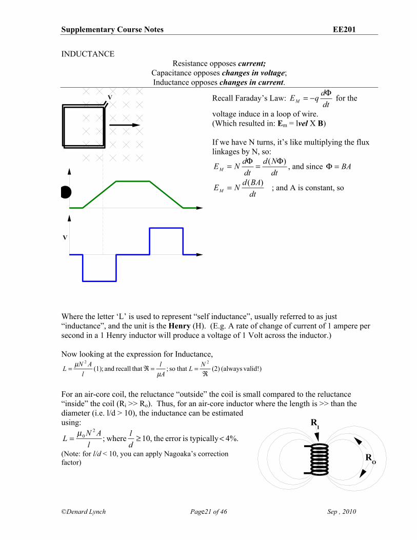
INDUCTANCE Resistance opposes current;
Capacitance opposes changes in voltage; Inductance opposes changes in current.
Recall Faraday’s Law: dtdqEM!"= for the
voltage induce in a loop of wire. (Which resulted in: Em = lvel X B) If we have N turns, it’s like multiplying the flux linkages by N, so:
dtNd
dtdNEM
)( !=!= , and since BA=!
dtBAdNEM)(= ; and A is constant, so
Where the letter ‘L’ is used to represent “self inductance”, usually referred to as just “inductance”, and the unit is the Henry (H). (E.g. A rate of change of current of 1 ampere per second in a 1 Henry inductor will produce a voltage of 1 Volt across the inductor.) Now looking at the expression for Inductance,
) valid!(always (2) that so ; that recall and ;(1) 22
!==!= NL
Al
lANL
µµ
For an air-core coil, the reluctance “outside” the coil is small compared to the reluctance “inside” the coil (Ri >> Ro). Thus, for an air-core inductor where the length is >> than the diameter (i.e. l/d > 10), the inductance can be estimated using:
4%. typicallyiserror the,10 where;2
0 <!=dl
lANL µ
(Note: for l/d < 10, you can apply Nagoaka’s correction factor)
V
V
!
RO
RI
Supplementary Course Notes EE201
©Denard Lynch Page22 of 46 Sep , 2010
Now go back for a moment to:
L =N 2
!; and "=NI = #!, (similar to V = IR) and substituting ! =
NI#
we are left with (also, always valid!).
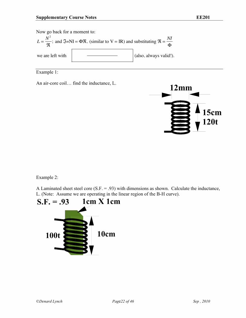
Example 1: An air-core coil… find the inductance, L. Example 2: A Laminated sheet steel core (S.F. = .93) with dimensions as shown. Calculate the inductance, L. (Note: Assume we are operating in the linear region of the B-H curve).
1cm X 1cm
10cm
S.F. = .93
100t
12mm
15cm
120t
Supplementary Course Notes EE201
©Denard Lynch Page23 of 46 Sep , 2010
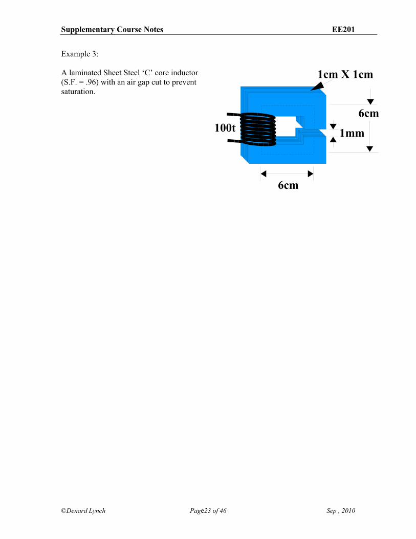
Example 3: A laminated Sheet Steel ‘C’ core inductor (S.F. = .96) with an air gap cut to prevent saturation.
1cm X 1cm
1mm
6cm
6cm
100t
Supplementary Course Notes EE201
©Denard Lynch Page24 of 46 Sep , 2010
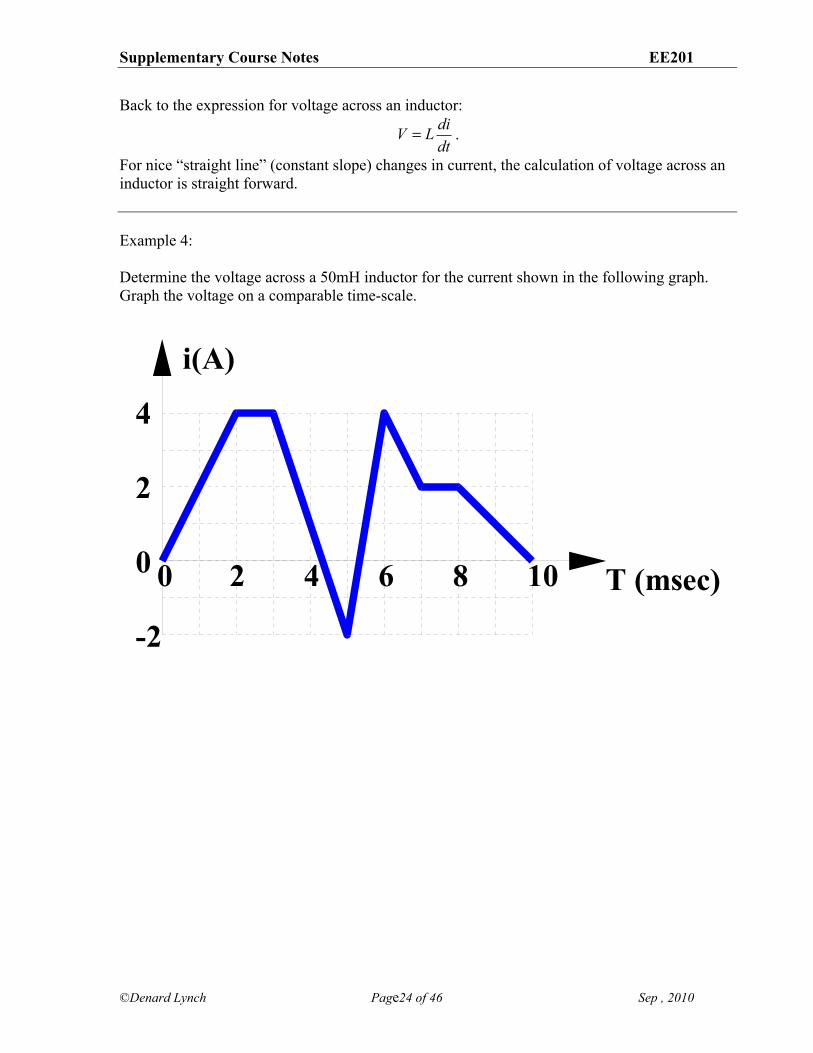
Back to the expression for voltage across an inductor:
dtdiLV = .
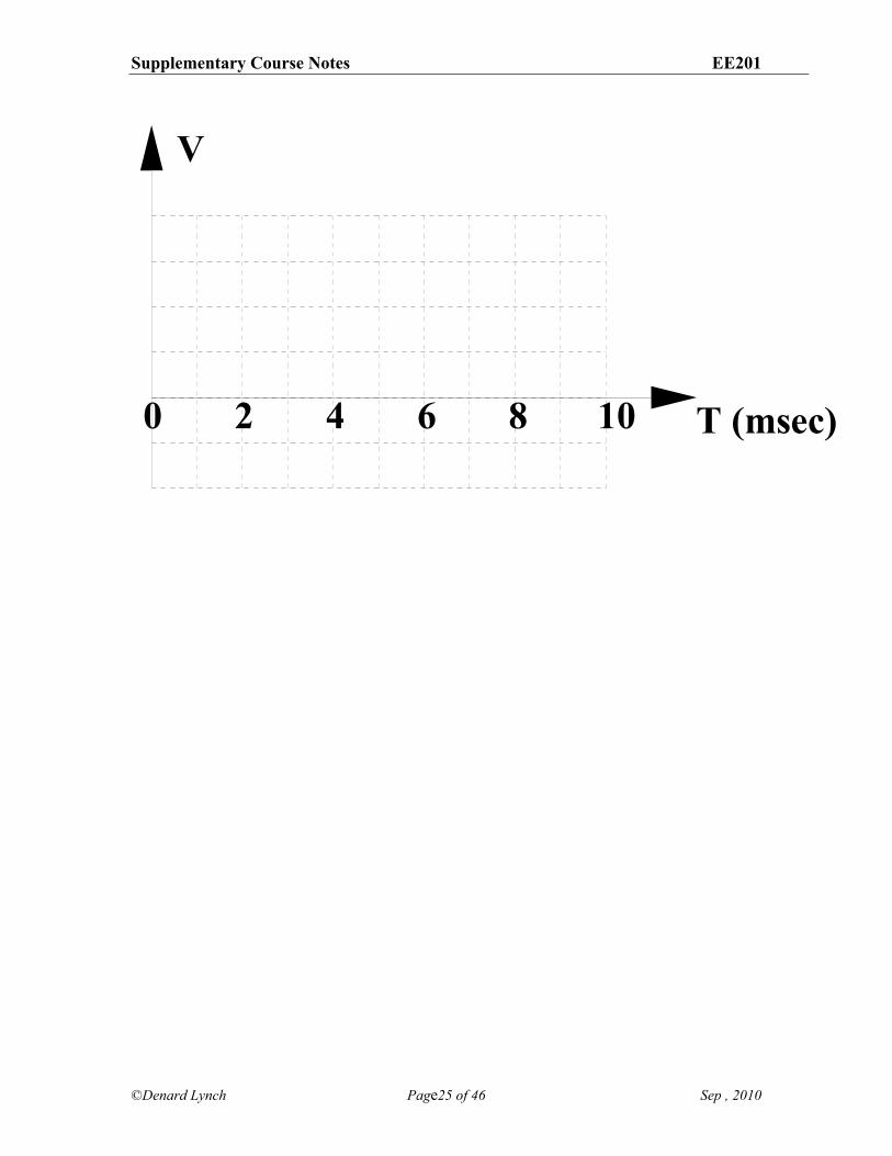
For nice “straight line” (constant slope) changes in current, the calculation of voltage across an inductor is straight forward. Example 4: Determine the voltage across a 50mH inductor for the current shown in the following graph. Graph the voltage on a comparable time-scale.
i(A)
T (msec)0 2 4 6 8 10
4
2
0
-2
Supplementary Course Notes EE201
©Denard Lynch Page25 of 46 Sep , 2010
V
T (msec)0 2 4 6 8 10
Supplementary Course Notes EE201
©Denard Lynch Page26 of 46 Sep , 2010
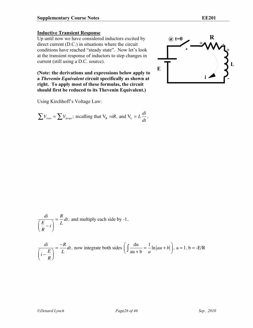
Inductive Transient Response Up until now we have considered inductors excited by direct current (D.C.) in situations where the circuit conditions have reached “steady state”. Now let’s look at the transient response of inductors to step changes in current (still using a D.C. source). (Note: the derivations and expressions below apply to a Thevenin Equivalent circuit specifically as shown at right. To apply most of these formulas, the circuit should first be reduced to its Thevenin Equivalent.) Using Kirchhoff’s Voltage Law:
Vrises = Vdrops; recalling that VR =!! iR, and VL = Ldidt
,
diER" i#
$%&'(=RLdt, and multiply each side by -1,
di
i " ER
#$%
&'(="RLdt, now integrate both sides du
au + b=
1a
ln au + b)#$%&'(
, a = 1, b = -E/R
R
EL
@ t=0
i
+ -+
-
Supplementary Course Notes EE201
©Denard Lynch Page27 of 46 Sep , 2010
lnI ! E
R
! ER
"
#
$$$
%
&
'''=!RLt, now use each side as an exponent of 'e'
eln
I !ER
!ER
"
#
$$$
%
&
'''= e
!RLt, and recall that eln(x ) = x, we get...
I ! ER
! ER
= e!RLt, multiply both sides by - E
R,
I !ER= !
ERe!RLt, and add - E
R to both sides...
Supplementary Course Notes EE201
©Denard Lynch Page28 of 46 Sep , 2010
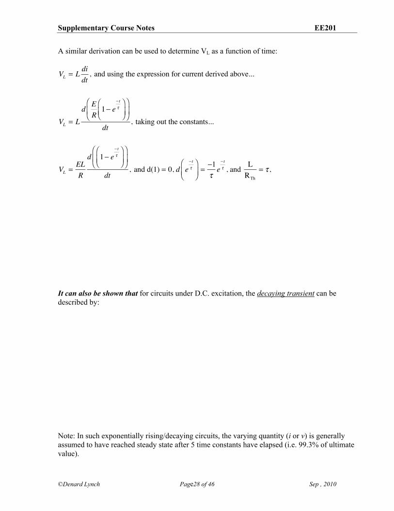
A similar derivation can be used to determine VL as a function of time:
VL = L didt
, and using the expression for current derived above...
VL = Ld E
R1! e
! t"
#$%
&'(
#
$%
&
'(
dt, taking out the constants...
VL =ELR
d 1! e! t"
#$%
&'(
#
$%
&
'(
dt, and d(1) = 0, d e
! t"
#$%
&'(=!1"e! t" , and L
RTh
= " ,
It can also be shown that for circuits under D.C. excitation, the decaying transient can be described by: Note: In such exponentially rising/decaying circuits, the varying quantity (i or v) is generally assumed to have reached steady state after 5 time constants have elapsed (i.e. 99.3% of ultimate value).
Supplementary Course Notes EE201
©Denard Lynch Page29 of 46 Sep , 2010
Initial Conditions: In the above derivations, we have ignored the possibility of any pre-existing constant terms in order to simplify the derivation. The implied assumption is that the current was at 0 at time t 0 (i.e. when the circuit conditions for the inductor changed). Of course, in many situations the initial current is not 0, and this pre-existing condition must be taken into consideration. A more general expression for the behaviour of exponentially rising or decaying quantities is given by:
( ) t
f f ix( t ) X X X e !"
= " " ; where Xi is the initial value of the quantity, and Xf is the final value. You can satisfy yourself that this expression correctly reduces to the expressions derived above for both voltage or current by substituting 0 for either the initial or final values. These expressions along with other circuit analysis techniques can be used to determine the initial and final values of the parameter in question.
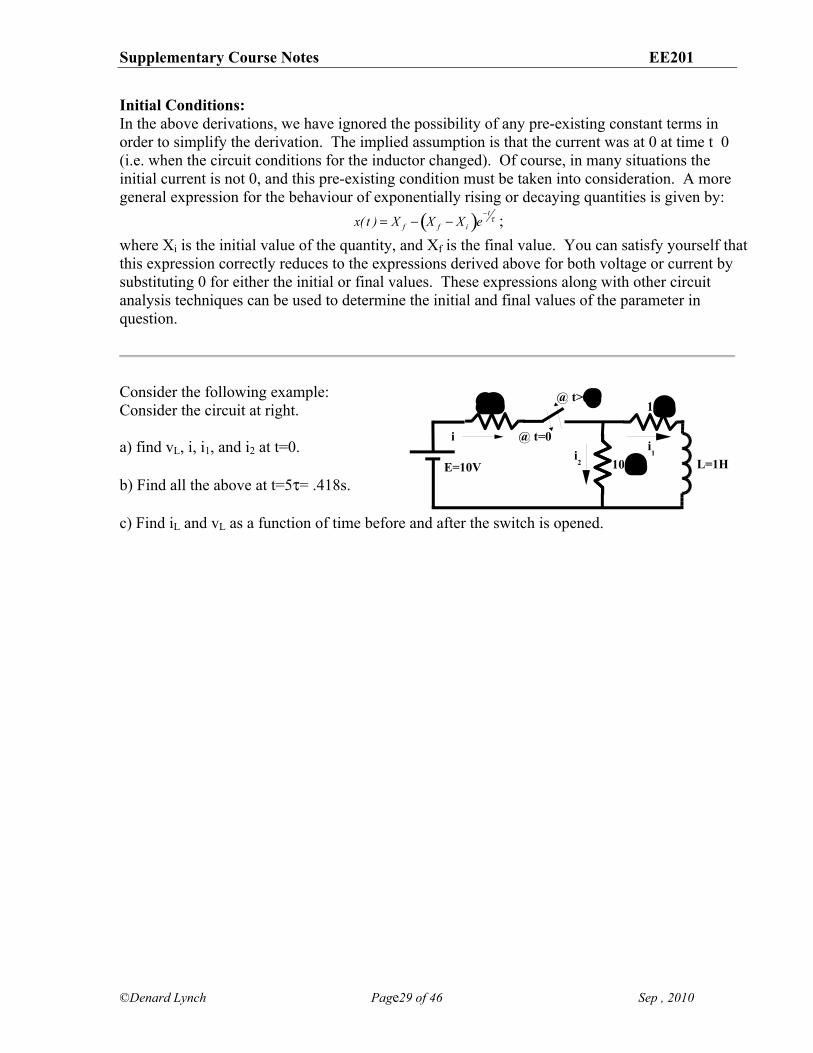
Consider the following example: Consider the circuit at right. a) find vL, i, i1, and i2 at t=0. b) Find all the above at t=5)= .418s. c) Find iL and vL as a function of time before and after the switch is opened.
E=10V L=1H
@ t=0
@ t>5!10"
100"
2"
ii2
i1
Supplementary Course Notes EE201
©Denard Lynch Page30 of 46 Sep , 2010
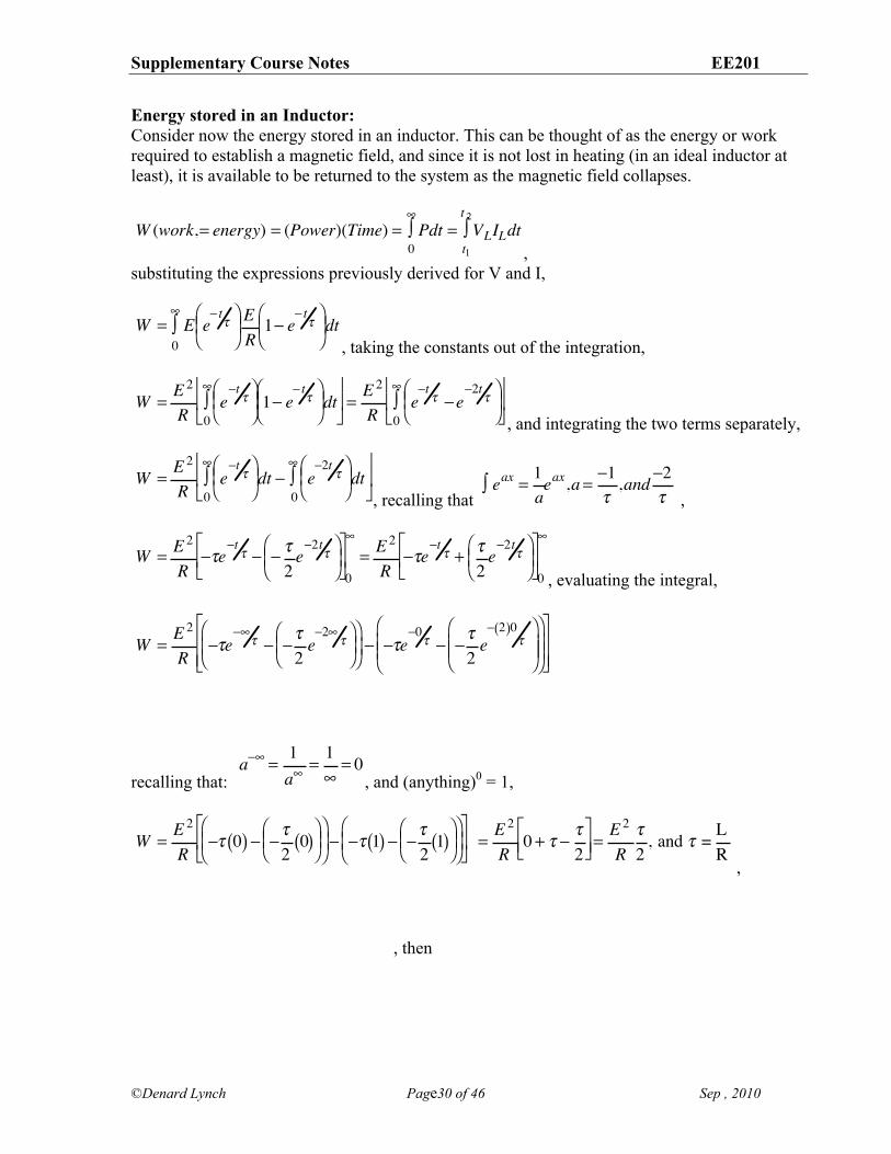
Energy stored in an Inductor: Consider now the energy stored in an inductor. This can be thought of as the energy or work required to establish a magnetic field, and since it is not lost in heating (in an ideal inductor at least), it is available to be returned to the system as the magnetic field collapses.
, substituting the expressions previously derived for V and I,
, taking the constants out of the integration,
, and integrating the two terms separately,
, recalling that ,
, evaluating the integral,
recalling that: , and (anything)0 = 1,
,
, then
W (work,= energy) = (Power)(Time) = Pdt = VLILdtt1
t 2!
0
"!
W = E e! t
"# $ %
& ' ( ER1! e
! t"#
$ %
& ' ( dt
0
)*
W =E 2
Re!t"#
$ %
& ' ( 1! e
! t"#
$ %
& ' ( dt
0
)*+
, -
.
/ 0 =
E 2
Re!t" !e
!2t"#
$ %
& ' (
0
)*+
, -
.
/ 0
W =E 2
Re!t
"# $ %
& ' ( dt ! e
!2t"#
$ %
& ' ( dt
0
)*
0
)*+
, -
.
/ 0
eax =1a
! eax,a ="1#,and
"2#
W = E 2
R!"e
!t" ! ! "
2e!2t
"# $ %
& ' (
)
* +
,
- . 0
/
= E 2
R!"e
!t" + "
2e!2t
"# $ %
& ' (
)
* +
,
- . 0
/
W =E 2
R!"e
!#" ! !
"2e!2#
"$ % &
' ( )
$
% &
'
( ) ! !"e
!0" ! !
"2e! 2( )0
"$
% & &
'
( ) )
$
% & &
'
( ) )
*
+ , ,
-
. / /
a!" =1a"
=1"
= 0
W =E 2
R!" 0( ) ! !
"2
0( )# $ %
& ' (
# $ %
& ' ( ! !" 1( ) ! !
"2
1( )# $ %
& ' (
# $ %
& ' (
)
* +
,
- . =
E 2
R0 + " !
"2
) * +
, - . =
E 2
R"2
, and " = LR
Supplementary Course Notes EE201
©Denard Lynch Page31 of 46 Sep , 2010
Consider as an example the inductor and the circuit from the previous example. At “steady state”, the current in the Inductor was 0.8196A. This means that the energy stored in the inductor would be:
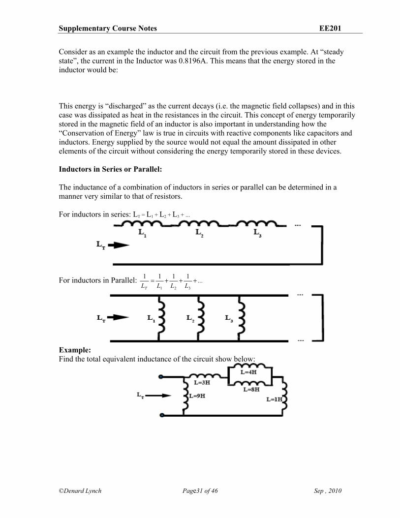
This energy is “discharged” as the current decays (i.e. the magnetic field collapses) and in this case was dissipated as heat in the resistances in the circuit. This concept of energy temporarily stored in the magnetic field of an inductor is also important in understanding how the “Conservation of Energy” law is true in circuits with reactive components like capacitors and inductors. Energy supplied by the source would not equal the amount dissipated in other elements of the circuit without considering the energy temporarily stored in these devices. Inductors in Series or Parallel: The inductance of a combination of inductors in series or parallel can be determined in a manner very similar to that of resistors. For inductors in series: LT = L1 + L2 + L3 + ...
For inductors in Parallel: ...LLLLT
+++=321
1111
Example: Find the total equivalent inductance of the circuit show below:
Supplementary Course Notes EE201
©Denard Lynch Page32 of 46 Sep , 2010
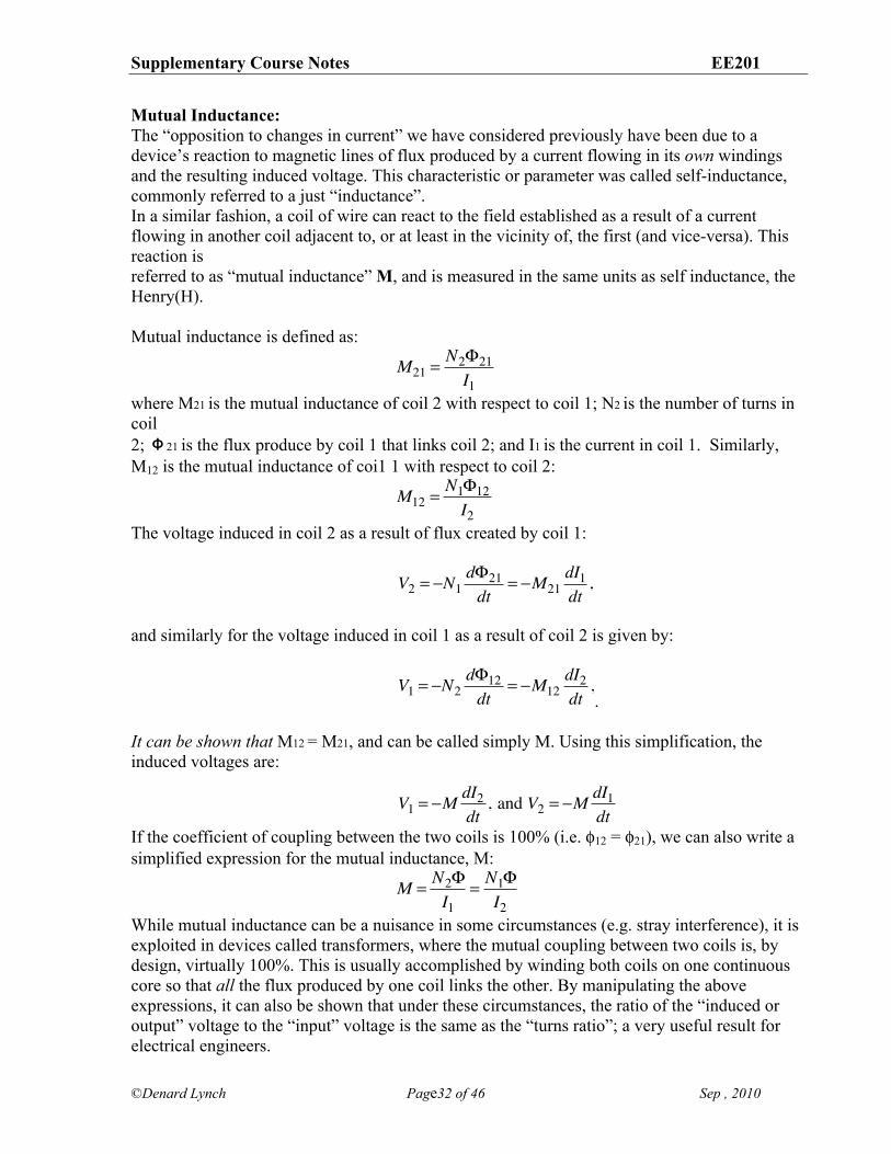
Mutual Inductance: The “opposition to changes in current” we have considered previously have been due to a device’s reaction to magnetic lines of flux produced by a current flowing in its own windings and the resulting induced voltage. This characteristic or parameter was called self-inductance, commonly referred to a just “inductance”. In a similar fashion, a coil of wire can react to the field established as a result of a current flowing in another coil adjacent to, or at least in the vicinity of, the first (and vice-versa). This reaction is referred to as “mutual inductance” M, and is measured in the same units as self inductance, the Henry(H). Mutual inductance is defined as:
where M21 is the mutual inductance of coil 2 with respect to coil 1; N2 is the number of turns in coil 2; Φ21 is the flux produce by coil 1 that links coil 2; and I1 is the current in coil 1. Similarly, M12 is the mutual inductance of coi1 1 with respect to coil 2:
The voltage induced in coil 2 as a result of flux created by coil 1:
and similarly for the voltage induced in coil 1 as a result of coil 2 is given by:
. It can be shown that M12 = M21, and can be called simply M. Using this simplification, the induced voltages are:
If the coefficient of coupling between the two coils is 100% (i.e. *12 = *21), we can also write a simplified expression for the mutual inductance, M:
While mutual inductance can be a nuisance in some circumstances (e.g. stray interference), it is exploited in devices called transformers, where the mutual coupling between two coils is, by design, virtually 100%. This is usually accomplished by winding both coils on one continuous core so that all the flux produced by one coil links the other. By manipulating the above expressions, it can also be shown that under these circumstances, the ratio of the “induced or output” voltage to the “input” voltage is the same as the “turns ratio”; a very useful result for electrical engineers.
M21 = N2!21I1
M12 = N1!12I2
V2 = !N1d"21dt
= !M21dI1dt,
V1 = !N2d"12dt
= !M12dI2dt,
V1 = !M dI2dt
, and V2 = !M dI1dt
M = N2!I1
= N1!I2
Supplementary Course Notes EE201
©Denard Lynch Page33 of 46 Sep , 2010
Capacitors and Capacitive Transients
Recall from PHY155 that the capacitance of an ideal parallel-plate capacitor, C = !r!oAd
,
where A = the plate area (m2), d = the distance between the plates (m), +o = permittivity of free space (8.854 X 10⁻¹² C2/N-m2), and +r is the relative permittivity of the dielectric between the two capacitor plates (a unit-
less number giving the ratio of the permittivity of the dielectric to that of a vacuum, with a vacuum considered essentially the same as space).
Also recall that the voltage across an ideal capacitor is proportional to the charge held on the
plates and inversely proportional to the amount of the capacitance: VC =QC
(Q in coulombs and
C in farads will give V in volts). Since the amount of charge is a function of the current and
how long it has been flowing, we can also write: VC =i ! tC
. An incremental increase in voltage
can be expressed: dVC =i !dtC
, and re-arranging, we get an expression for the current:
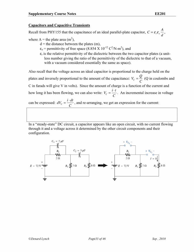
In a “steady-state” DC circuit, a capacitor appears like an open circuit, with no current flowing through it and a voltage across it determined by the other circuit components and their configuration.
Supplementary Course Notes EE201
©Denard Lynch Page34 of 46 Sep , 2010
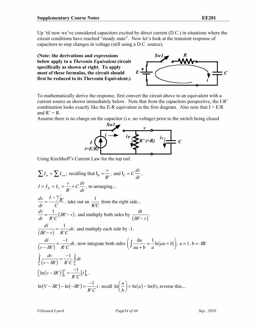
Up ‘til now we’ve considered capacitors excited by direct current (D.C.) in situations where the circuit conditions have reached “steady state”. Now let’s look at the transient response of capacitors to step changes in voltage (still using a D.C. source). (Note: the derivations and expressions below apply to a Thevenin Equivalent circuit specifically as shown at right. To apply most of these formulas, the circuit should first be reduced to its Thevenin Equivalent.) To mathematically derive the response, first convert the circuit above to an equivalent with a current source as shown immediately below. Note that from the capacitors perspective, the I-R’ combination looks exactly like the E-R equivalent in the first diagram. Also note that I = E/R and R’ = R. Assume there is no charge on the capacitor (i.e. no voltage) prior to the switch being closed
Using Kirchhoff’s Current Law for the top rail:
Iin = Iout ; recalling that IR =!! vR '
, and IC = Cdvdt
,
I = IR ' + IC =vR '
+ C dvdt
, re-arranging...
dvdt
=I ! v R 'C
, take out an 1R'C
from the right side...
dvdt
=1R 'C
IR '! v( ), and multiply both sides by dtIR '! v( ) ,
diIR '! v( ) =
1R 'C
dt, and multiply each side by -1,
div ! IR '( ) =
!1R 'C
dt, now integrate both sides duau + b
=1a
ln au + b"#$%&'(
, a = 1, b = -IR'
dvv ! IR '( ) =
!1R 'C
dt0
t
"0
v
"
ln v ! IR '( )"# $%0V =
!1R 'C
t[ ]0t ,
ln V ! IR '( ) ! ln !IR '( ) = !1R 'C
t, recall ln ab
"#$
%&'= ln a( ) ! ln(b), reverse this...
I (=E/R)
Sw1
R’ (=R) C
vi iR’ iC
+E
Sw1 R
Ci
Supplementary Course Notes EE201
©Denard Lynch Page35 of 46 Sep , 2010
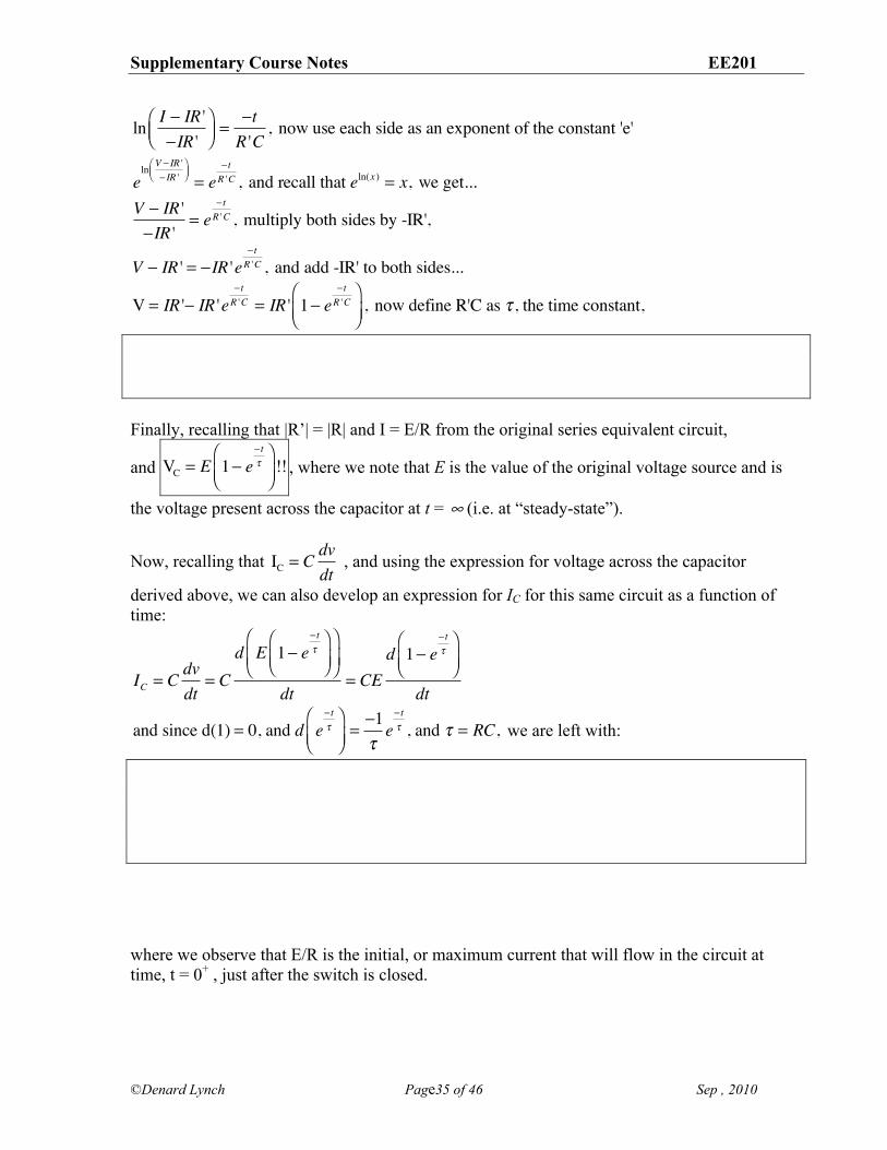
ln I ! IR '!IR '
"#$
%&'=
!tR 'C
, now use each side as an exponent of the constant 'e'
eln V ! IR '
! IR '"#$
%&' = e
! tR 'C , and recall that eln(x ) = x, we get...
V ! IR '!IR '
= e! tR 'C , multiply both sides by -IR',
V ! IR ' = !IR 'e! tR 'C , and add -IR' to both sides...
V = IR '! IR 'e! tR 'C = IR ' 1! e
! tR 'C
"#$
%&'
, now define R'C as ( , the time constant,
Finally, recalling that |R’| = |R| and I = E/R from the original series equivalent circuit,
and VC = E 1! e! t"
#$%
&'(!! , where we note that E is the value of the original voltage source and is
the voltage present across the capacitor at t = & (i.e. at “steady-state”).
Now, recalling that IC = Cdvdt
, and using the expression for voltage across the capacitor
derived above, we can also develop an expression for IC for this same circuit as a function of time:
IC = C dvdt
= Cd E 1! e
! t"
#$%
&'(
#
$%&
'(
dt= CE
d 1! e! t"
#$%
&'(
dt
and since d(1) = 0, and d e! t"
#$%
&'(=!1"e! t" , and " = RC, we are left with:
where we observe that E/R is the initial, or maximum current that will flow in the circuit at time, t = 0+ , just after the switch is closed.
Supplementary Course Notes EE201
©Denard Lynch Page36 of 46 Sep , 2010
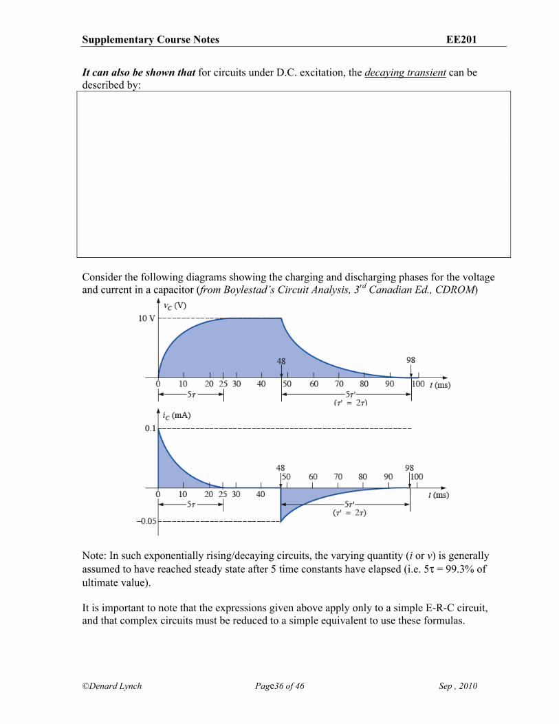
It can also be shown that for circuits under D.C. excitation, the decaying transient can be described by: Consider the following diagrams showing the charging and discharging phases for the voltage and current in a capacitor (from Boylestad’s Circuit Analysis, 3rd Canadian Ed., CDROM)
Note: In such exponentially rising/decaying circuits, the varying quantity (i or v) is generally assumed to have reached steady state after 5 time constants have elapsed (i.e. 5) = 99.3% of ultimate value). It is important to note that the expressions given above apply only to a simple E-R-C circuit, and that complex circuits must be reduced to a simple equivalent to use these formulas.
Supplementary Course Notes EE201
©Denard Lynch Page37 of 46 Sep , 2010
Initial Conditions: In the above derivations, we have ignored the possibility of any pre-existing constant terms in order to simplify the derivation. The implied assumption is that the voltage was at 0 at time t 0 (i.e. when the circuit conditions for the capacitor changed). Of course, in many situations the initial voltage is not 0, and this pre-existing condition must be taken into consideration. A more general expression for the behaviour of exponentially rising or decaying quantities is given by:
( ) t
f f ix( t ) X X X e !"
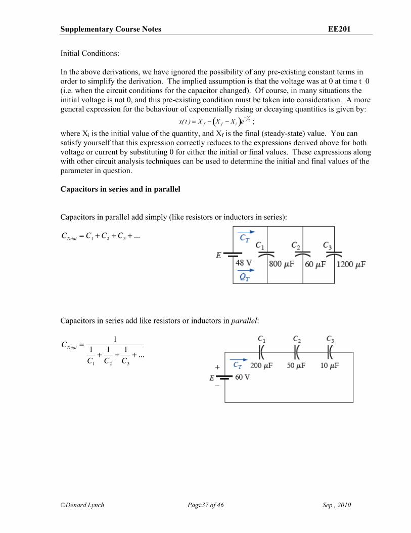
= " " ; where Xi is the initial value of the quantity, and Xf is the final (steady-state) value. You can satisfy yourself that this expression correctly reduces to the expressions derived above for both voltage or current by substituting 0 for either the initial or final values. These expressions along with other circuit analysis techniques can be used to determine the initial and final values of the parameter in question. Capacitors in series and in parallel Capacitors in parallel add simply (like resistors or inductors in series): CTotal = C1 + C2 + C3 + ... Capacitors in series add like resistors or inductors in parallel:
CTotal =1
1C1
+ 1C2
+ 1C3
+ ...
Supplementary Course Notes EE201
©Denard Lynch Page38 of 46 Sep , 2010
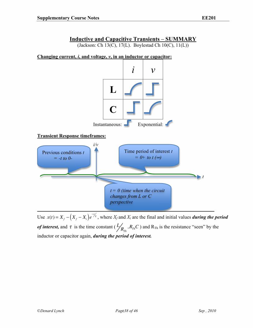
Inductive and Capacitive Transients – SUMMARY
(Jackson: Ch 13(C), 17(L). Boylestad Ch 10(C), 11(L)) Changing current, i, and voltage, v, in an inductor or capacitor:
i v
L
C
Instantaneous: Exponential: Transient Response timeframes:
Use x(t) = X f ! X f ! Xi( )e! t " , where Xf and Xi are the final and initial values during the period
of interest, and ! is the time constant ( L RTh,RThC ) and RTh is the resistance “seen” by the
inductor or capacitor again, during the period of interest.
i/v
t
t = 0 (time when the circuit changes from L or C perspective
Time period of interest t = 0+ to t (&)
Previous conditions t = -t to 0-
Supplementary Course Notes EE201
©Denard Lynch Page39 of 46 Sep , 2010
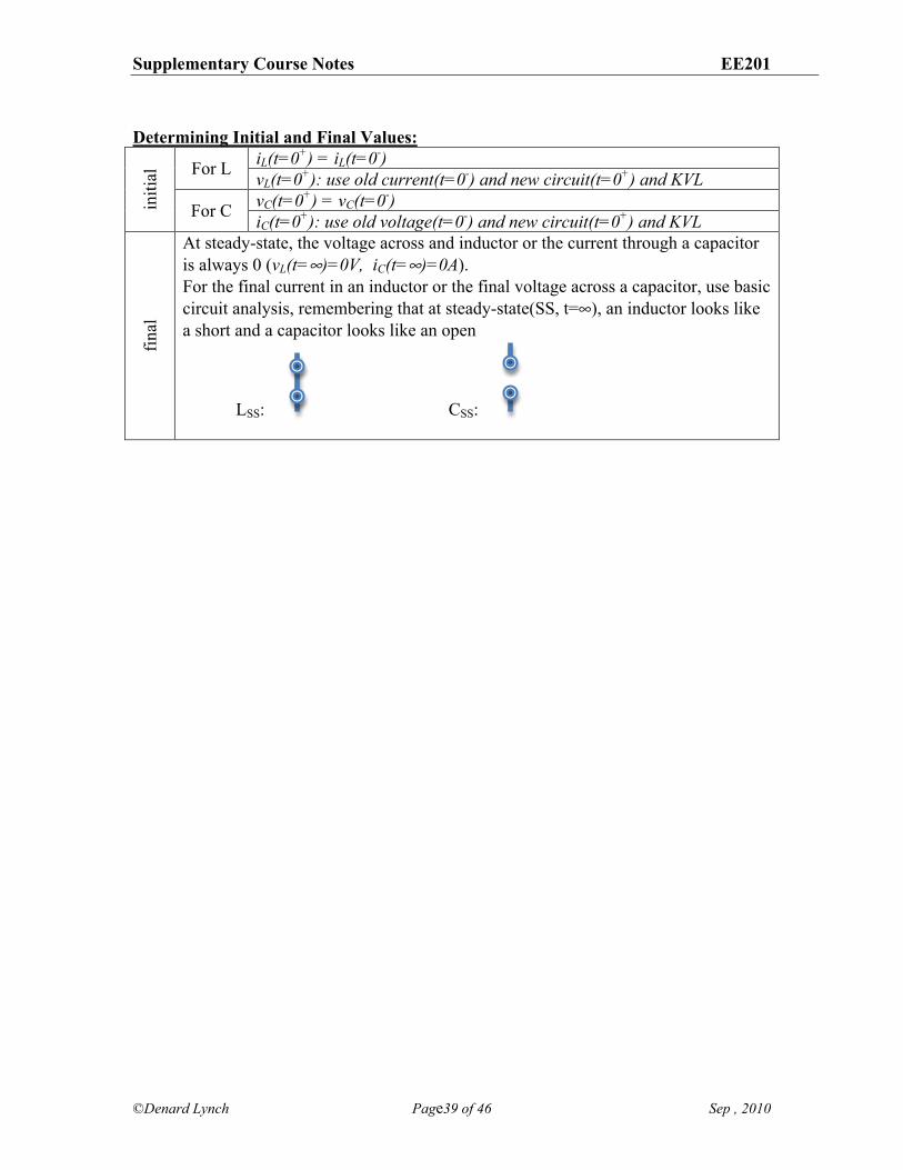
Determining Initial and Final Values:
iL(t=0+) = iL(t=0-) For L vL(t=0+): use old current(t=0-) and new circuit(t=0+) and KVL vC(t=0+) = vC(t=0-) in
itial
For C iC(t=0+): use old voltage(t=0-) and new circuit(t=0+) and KVL
final
At steady-state, the voltage across and inductor or the current through a capacitor is always 0 (vL(t=&)=0V, iC(t=&)=0A). For the final current in an inductor or the final voltage across a capacitor, use basic circuit analysis, remembering that at steady-state(SS, t=,), an inductor looks like a short and a capacitor looks like an open
LSS: CSS:
Supplementary Course Notes EE201
©Denard Lynch Page40 of 46 Sep , 2010
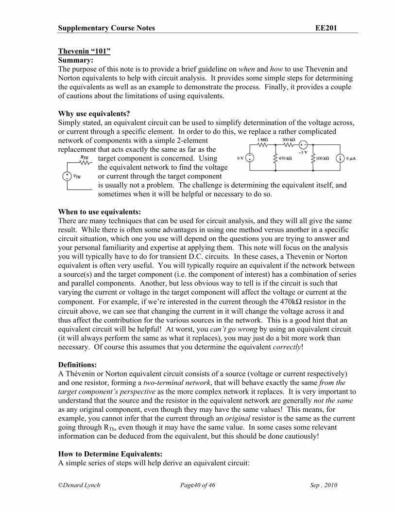
Thevenin “101” Summary: The purpose of this note is to provide a brief guideline on when and how to use Thevenin and Norton equivalents to help with circuit analysis. It provides some simple steps for determining the equivalents as well as an example to demonstrate the process. Finally, it provides a couple of cautions about the limitations of using equivalents. Why use equivalents? Simply stated, an equivalent circuit can be used to simplify determination of the voltage across, or current through a specific element. In order to do this, we replace a rather complicated network of components with a simple 2-element replacement that acts exactly the same as far as the
target component is concerned. Using the equivalent network to find the voltage or current through the target component is usually not a problem. The challenge is determining the equivalent itself, and sometimes when it will be helpful or necessary to do so.
When to use equivalents: There are many techniques that can be used for circuit analysis, and they will all give the same result. While there is often some advantages in using one method versus another in a specific circuit situation, which one you use will depend on the questions you are trying to answer and your personal familiarity and expertise at applying them. This note will focus on the analysis you will typically have to do for transient D.C. circuits. In these cases, a Thevenin or Norton equivalent is often very useful. You will typically require an equivalent if the network between a source(s) and the target component (i.e. the component of interest) has a combination of series and parallel components. Another, but less obvious way to tell is if the circuit is such that varying the current or voltage in the target component will affect the voltage or current at the component. For example, if we’re interested in the current through the 470k% resistor in the circuit above, we can see that changing the current in it will change the voltage across it and thus affect the contribution for the various sources in the network. This is a good hint that an equivalent circuit will be helpful! At worst, you can’t go wrong by using an equivalent circuit (it will always perform the same as what it replaces), you may just do a bit more work than necessary. Of course this assumes that you determine the equivalent correctly! Definitions: A Thévenin or Norton equivalent circuit consists of a source (voltage or current respectively) and one resistor, forming a two-terminal network, that will behave exactly the same from the target component’s perspective as the more complex network it replaces. It is very important to understand that the source and the resistor in the equivalent network are generally not the same as any original component, even though they may have the same values! This means, for example, you cannot infer that the current through an original resistor is the same as the current going through RTh, even though it may have the same value. In some cases some relevant information can be deduced from the equivalent, but this should be done cautiously! How to Determine Equivalents: A simple series of steps will help derive an equivalent circuit:
Supplementary Course Notes EE201
©Denard Lynch Page41 of 46 Sep , 2010
1. define two terminals isolating the component of interest (target component), 2. “remove” the target component, and determine the resistance “looking back” into the
terminals with the sources replaced by their internal resistance (a short for voltage sources and an open for current sources),
3. determine the “open circuit” voltage (Thévenin) or short circuit current (Norton) at the terminals,
4. use the source and resistance to build a series network (voltage source, resistor =, Thévenin) or parallel network (current source, resistor = Norton) and attach it to the two terminals in place of the original network.
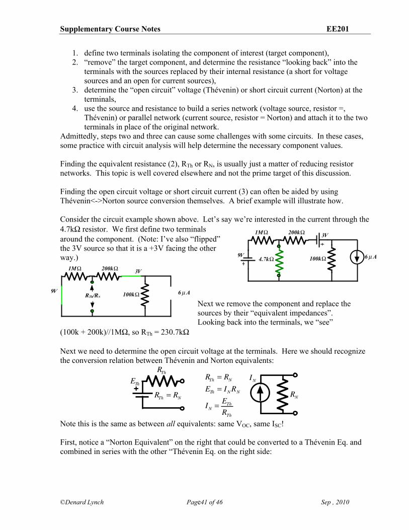
Admittedly, steps two and three can cause some challenges with some circuits. In these cases, some practice with circuit analysis will help determine the necessary component values. Finding the equivalent resistance (2), RTh or RN, is usually just a matter of reducing resistor networks. This topic is well covered elsewhere and not the prime target of this discussion. Finding the open circuit voltage or short circuit current (3) can often be aided by using Thévenin<->Norton source conversion themselves. A brief example will illustrate how. Consider the circuit example shown above. Let’s say we’re interested in the current through the 4.7k% resistor. We first define two terminals around the component. (Note: I’ve also “flipped” the 3V source so that it is a +3V facing the other way.)
Next we remove the component and replace the sources by their “equivalent impedances”. Looking back into the terminals, we “see”
(100k + 200k)//1M%, so RTh = 230.7k% Next we need to determine the open circuit voltage at the terminals. Here we should recognize the conversion relation between Thévenin and Norton equivalents:
Note this is the same as between all equivalents: same VOC, same ISC! First, notice a “Norton Equivalent” on the right that could be converted to a Thévenin Eq. and combined in series with the other “Thévenin Eq. on the right side:
+RTh = RNETh = INRN
IN = EThRTh
RTh
RNRTh = RN
ETh IN
1M!
100k!4.7k!
200k!
6µA9V
3V
1M!
100k!
200k!
6µA9V
3V
RTh/RN
Supplementary Course Notes EE201
©Denard Lynch Page42 of 46 Sep , 2010
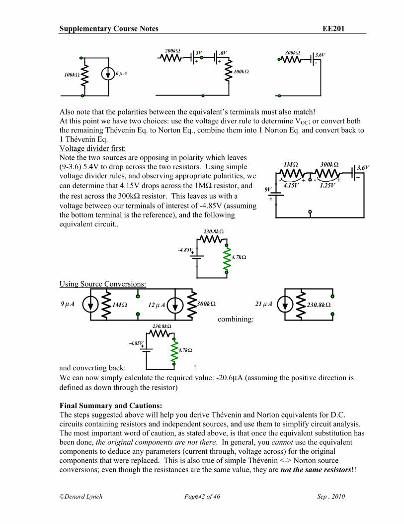
Also note that the polarities between the equivalent’s terminals must also match! At this point we have two choices: use the voltage diver rule to determine VOC; or convert both the remaining Thévenin Eq. to Norton Eq., combine them into 1 Norton Eq. and convert back to 1 Thévenin Eq. Voltage divider first: Note the two sources are opposing in polarity which leaves (9-3.6) 5.4V to drop across the two resistors. Using simple voltage divider rules, and observing appropriate polarities, we can determine that 4.15V drops across the 1M% resistor, and the rest across the 300k% resistor. This leaves us with a voltage between our terminals of interest of -4.85V (assuming the bottom terminal is the reference), and the following equivalent circuit..
Using Source Conversions:
combining:
and converting back: ! We can now simply calculate the required value: -20.6µA (assuming the positive direction is defined as down through the resistor) Final Summary and Cautions: The steps suggested above will help you derive Thévenin and Norton equivalents for D.C. circuits containing resistors and independent sources, and use them to simplify circuit analysis. The most important word of caution, as stated above, is that once the equivalent substitution has been done, the original components are not there. In general, you cannot use the equivalent components to deduce any parameters (current through, voltage across) for the original components that were replaced. This is also true of simple Thévenin <-> Norton source conversions; even though the resistances are the same value, they are not the same resistors!!
100k! 6µA 100k!
200k! 3V .6V 300k! 3.6V
+
230.8k!
-4.85V4.7k!
1M! 300k!12µA9µA 230.8k!21µA
+
230.8k!
-4.85V4.7k!
1M! 300k!
9V
3.6V
4.15V 1.25V+ +- -
Supplementary Course Notes EE201
©Denard Lynch Page43 of 46 Sep , 2010
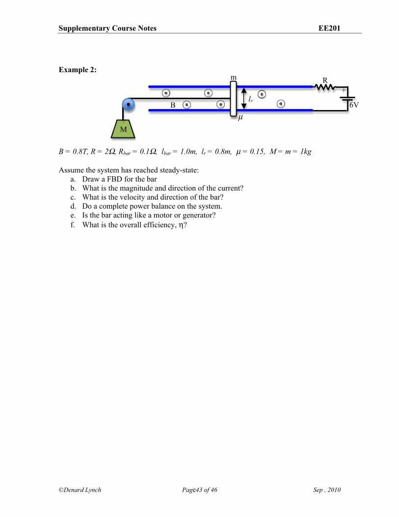
Example 2: B = 0.8T, R = 2', Rbar = 0.1', lbar = 1.0m, lr = 0.8m, µ = 0.15, M = m = 1kg Assume the system has reached steady-state:
a. Draw a FBD for the bar b. What is the magnitude and direction of the current? c. What is the velocity and direction of the bar? d. Do a complete power balance on the system. e. Is the bar acting like a motor or generator? f. What is the overall efficiency, -?
m
M
B µ
lr
R
6V
+
Supplementary Course Notes EE201
©Denard Lynch Page44 of 46 Sep , 2010
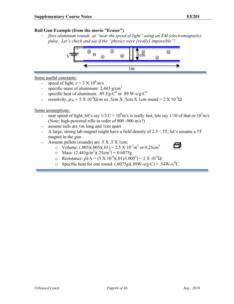
Rail Gun Example (from the movie ”Eraser”) - fires aluminum rounds at “near the speed of light” using an EM (electromagnetic)
pulse. Let’s check and see if the “physics were [really] impossible”!
Some useful constants:
- speed of light, c = 3 X 10⁸ m/s - specific mass of aluminum: 2.443 g/cm3 - specific heat of aluminum: .89 J/g-C0 or .89 W-s/g-C0 - resistivity, .Al = 5 X 10⁻⁸%-m so .5cm X .5cm X 1cm round = 2 X 10⁻⁵%
Some assumptions:
- near speed of light, let’s say 1/3 C = 108m/s is really fast, lets say 1/10 of that or 107m/s (Note: high-powered rifle in order of 800 -900 m/s?)
- assume rails are 1m long and 1cm apart - A large, strong lab magnet might have a field density of 2.5 – 5T; let’s assume a 5T
magnet in the gun - Assume pellets (rounds) are .5 X .5 X 1cm:
o Volume: (.005)(.005)(.01) = 2.5 X 10⁻⁷m3 or 0.25cm3 o Mass: (2.443g/m3)(.25cm3) = 0.6075g o Resistance: .l/A = (5 X 10⁻⁸)(.01)/(.0052) = 2 X 10⁻⁵% o Specific heat for one round: (.6075g)(.89W-s/g-C) = .54W-s/0C
B +
1m
1cm V
Supplementary Course Notes EE201
©Denard Lynch Page45 of 46 Sep , 2010
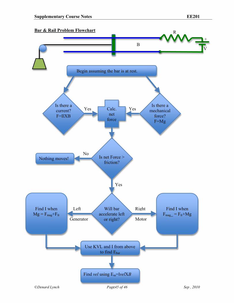
Bar & Rail Problem Flowchart
Nothing moves!
B
M
R
V
+
Generator Motor
Right Left
Yes
Yes Yes
No
Find vel using Em=lvelXB
Use KVL and I from above to find Ebar
Find I when Mg = Fmag+Ffr
Find I when Fmag_ = Ffr+Mg
Will bar accelerate left
or right?
Is net Force > friction?
Calc. net
force
Is there a mechanical
force? F=Mg
Is there a current? F=IlXB
Begin assuming the bar is at rest.

Supplementary Course Notes EE201
©Denard Lynch Page46 of 46 Sep , 2010