
EE051 Pneumatic Th Inst
63
SRI LANKA INSTITUTE of ADVANCED TECHNOLOGICAL EDUCATION Training Unit Pneumatic Theory No: EE 051 INDUSTRIETECHNIK INDUSTRIETECHNIK ELECTRICAL and ELECTRONIC ENGINEERING Instructor Manual
description
HNDE Colombo 15
Transcript of EE051 Pneumatic Th Inst
SRI LANKA INSTITUTE of ADVANCED TECHNOLOGICAL EDUCATION
Training Unit
Pneumatic
Theory
No: EE 051
INDUSTRIETECHNIKINDUSTRIETECHNIK
ELECTRICAL and ELECTRONIC ENGINEERING
Instructor Manual
1
Training Unit
Pneumatic
Theory Part
No.: EE 051
Edition: 2008 All Rights Reserved Editor: MCE Industrietechnik Linz GmbH & Co Education and Training Systems, DM-1 Lunzerstrasse 64 P.O.Box 36, A 4031 Linz / Austria Tel. (+ 43 / 732) 6987 – 3475 Fax (+ 43 / 732) 6980 – 4271 Website: www.mcelinz.com

2
PNEUMATIC
LIST OF CONTENTS
CONTENTS
Learning objectives 4
1. INTRODUCTION TO PNEUMATIC 5
1.1 Definition of “Pneumatics” 5
1.2 Application of “Pneumatics” 5
1.3 Physical basic principles 5
1.4 Characteristics of compressed air 6
1.4.1 Advantages and disadvantages of compressed
air techniques 6
1.4.2 Cost comparison with other types of energy 7
2. PNEUMATIC ELEMENTS 8
2.1 Working elements 8
2.1.1 Single-acting cylinder 9
2.1.2 Double-acting cylinders 12
2.1.3 Calculation of force 15
2.2 Signal and Control elements 18
2.2.1 Types of valves and their function 18
2.2.2 Directional valves 18
2.2.3 Disc seat valves (3/2-way) 23
2.2.4 Disc seat valve (4/2-way) 24
2.2.5 Horizontal spool valve 25
2.2.6 Actuation of a valve 27
2.2.7 Duration of actuation 29
2.2.8 Flow control valve 29
2.2.9 Non-return valves 30
2.2.10 Throttle relief valve 30
2.2.11 Quick-exhaust valve 31
2.2.12 Shuttle valve (or-function) 32
2.2.13 Two pressure valve (and-function) 33
2.2.14 Other types of valves 33

3
3. SYSTEM OF CONTROL 36
3.1 Circuit diagrams 36
3.1.1 Representative of circuit diagrams 36
3.1.2 Numerical notation 37
3.1.3 Drawing conventions 38
3.2 Diagrams 39
3.2.1 Travel-phase diagrams 39
3.2.2 Travel-time diagrams 41
3.2.3 Valve-phase diagrams 41
3.3 Types of control 43
3.3.1 Manual control 43
3.3.2 Travel control 44
3.3.3 Manual and travel control 44
3.3.4 Time control 45
3.3.5 Manual and time control 46
4. COMPRESSORS 47
4.1 Types of compressors 47
4.1.1 Positive displacement compressors 47
4.1.2 Flow compressors 48
4.1.3 Pressure and delivery volumes of compressor types 48
4.2 Regulation of compressors 49
5. MAINTENANCE OF PNEUMATIC INSTALLATIONS 50
5.1 Maintenance 50
5.1.1 Daily maintenance 50
5.1.2 Weekly maintenance 50
5.1.3 Monthly maintenance 51
5.1.4 Annual maintenance 51
6. CONSTRUCTION OF A COMPRESSED AIR SYSTEM 52
4
PNEUMATIC
LEARNING OBJECTIVES
The participant should ...
explain the meaning of “Pneumatic”.
give three examples of applied “Pneumatics”.
list the three most important components of air.
name the measuring unit for pressure.
list three properties of compressed air.
state three advantages and three disadvantages of “Pneumatics” and comment on
these.
classify pneumatic elements.
give examples of cylinder applications.
distinguish between single-acting and double-acting cylinders according to their
operation and components.
distinguish between signal units and control units according to their functions.
list five types of valve and explain their operation.
describe the operation of all the control systems mentioned.
describe the general symbol for a valve.
indicate the types of actuation of valves.
explain how an adjustable throttle valve operates.
explain how a throttle relief valve operates.
explain how a quick-exhaust valve operates.
explain how an AND-valve (two pressure valve) operates.
differentiate between manual, travel and time controlled systems.
explain how a time delay valve functions.
name three types of compressed air pump.
sketch two types of compressor and explain their working principle.
state why it is necessary to regulate air pressure.
describe, with the aid of sketches, the operation of two systems of pressure regulation.
state why it is necessary to maintain pneumatic plants.
explain how a shuttle valve operates.
5
PNEUMATIC
1. INTRODUCTION TO PNEUMATICS
1.1 Definition of “pneumatics”
Pneumatics is the science of mechanical properties of elastic fluids. In industry
“Pneumatics” generally refers to the use of compressed air to transmit power and/or
motion.
1.2 Application of “Pneumatics”
Pneumatic devices include compressed air brakes (trucks and railways); percussion
drilling and other compressed air tools (mining and construction industry); pneumatic tube
conveyor systems, compressors and turbines. Pneumatic devices include also those
which use compressed air for cooling.
1.3 Physical basic principles
In pneumatic we are dealing with compressed air. This compressed air is derived from the
atmosphere. Air is a mixture of gases with the following approximate composition by
volume:
78% nitrogen, 21% oxygen, 1% other gases i.e. carbon dioxide, hydrogen, argon, krypton,
neon, xenon and helium.

6
The following term and units are used:
Unit Symbol Standard System SI
Mass
Time
Length
Area
Volume
Force
Rate of flow
Pressure
m
t
I
A
V
F
Q
P
kg (kilogram)
s (second)
m (metre)
m2 (square metre)
m3 (cubic metre)
N (Newton)
m3/ s
Pa (Pascal)
bar
Notes:
1 N = 1 kg m/ s2
1 Pa = 1 N/ m2
1 bar = 105 Pa
1.4 Characteristic of compressed air
- Air is compressible.
- The direction and velocity of flow of air in a system can be controlled.
- Air flows from a state of high pressure to a state of lower pressure. The higher the
pressure difference between different points, the higher the resulting rate of flow.
1.4.1 Advantages and disadvantages of compressed air technique
Advantages:
- Air is a gas mixture which is non-explosive.
Therefore, pneumatic systems are not subject to the same stringent safety precaution
as system using explosive gases. Note that compressed air is dangerous if
mishandled.
7
- Air is available in unlimited supply.
- Compressed air can be transmitted over long distances in pipelines.
Return pipelines are not necessary.
- Compressed air can be stored in pressure tanks, cylinders and used as a
transportable power supply.
- The working speed of pistons in pneumatic systems is in the range of 1-2 m/s; with
cylinders on which a quick exhaust valve is fitted speed up to 10 m/s can be realized.
- Pneumatic systems are overload-proof. Compressed air equipment can be used up to
and beyond maximum load without creating unsafe conditions. Note the overheating
resulting from an overload condition in an electric motor.
- Speed and movement can be controlled.
- Compressed air is a comparatively clean and low-pollution medium and, therefore, can
be used almost everywhere e.g. in the wood, metal, leather, textile and food
industries.
- Clean and dry compressed air works perfectly, even under extremes of temperature.
Disadvantages:
- Air absorbs moisture and drying may have to be considered.
- The exhaust air causes noise. Costly sound absorbers may be required.
- There is a limit to the pressure which can be used in a compressed air system.
1.4.2 Cost comparison with other types of energy
Compared with electrical energy, other types of energy are generally more expensive.
Hydraulic energy may cost 8 to 10 times as much.
Pneumatic energy may cost 10 to 12 times as much.
Manual work costs about 500 times as much as the equivalent electrical energy.
8
2. PNEUMATIC ELEMENTS
Pneumatic systems consist of working, signal and control elements.
The signal and control elements are termed valves.
They control the operation of working elements.
These working elements are mainly cylinders.
2.1 Working elements (cylinders)
Cylinders are working elements, which are suitable for linear movements.
They are used for various operational actions, such as tensioning, lifting, lowering, pulling,
locking, switching, discharging, braking and directing.
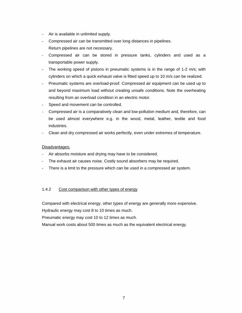
A distinction can be made between two types of cylinder according to their working action
a) single-acting cylinders
b) double-acting cylinders
a)
b)
SHOW FOIL
No.: 1
A single-acting cylinder can apply pressure in one direction only.
A double-acting cylinder can apply pressure in both directions (advance stroke and return
stroke).

9
2.1.1 Single-acting cylinder
In the single acting cylinders, compressed air is applied only to one side of the piston.
Work can, therefore, be done in one direction only.
The working stroke is caused by the compressed air, the return stroke is usually effected
by a built-in spring.
When the cylinder is arranged vertically the piston can return to its starting position by its
own weight.
The maximum length of working stroke is about 150 mm.
2.1.1.1 Working positions of the single-acting cylinder
Starting position:
The built-in spring keeps the piston in the starting position.
SHOW FOIL No.:2
Working stroke:
The piston is moved when compressed air is applied via the compressed air connection.
The air on the piston rod side is release via the air relief hole vent. The spring is
compressed.
SHOW FOIL No.:2
10
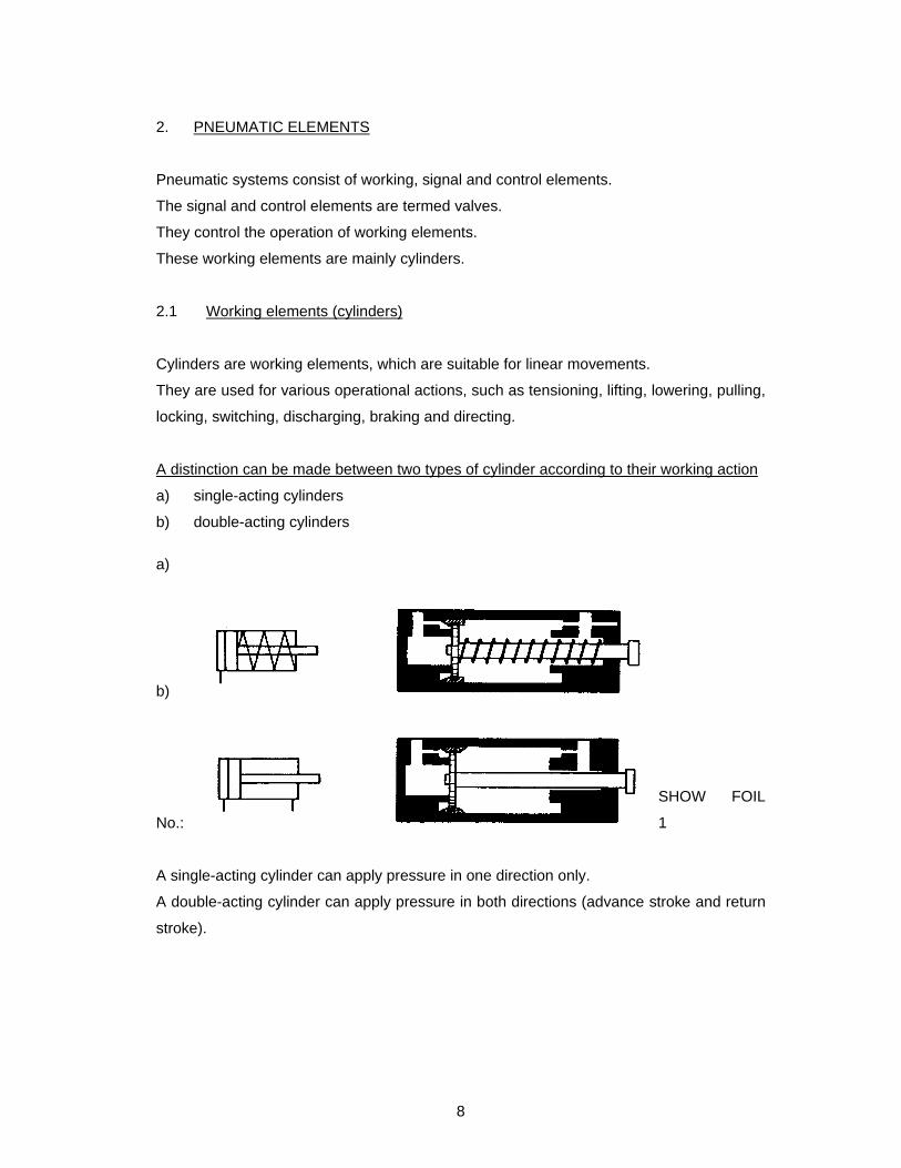
Return stroke:
When compressed air no longer applied, the spring will push the piston back to the
starting position. The air which is no longer under pressure is released via the exhaust
connection. The piston rod side of the cylinder fills via the vent.
SHOW FOIL No.:2
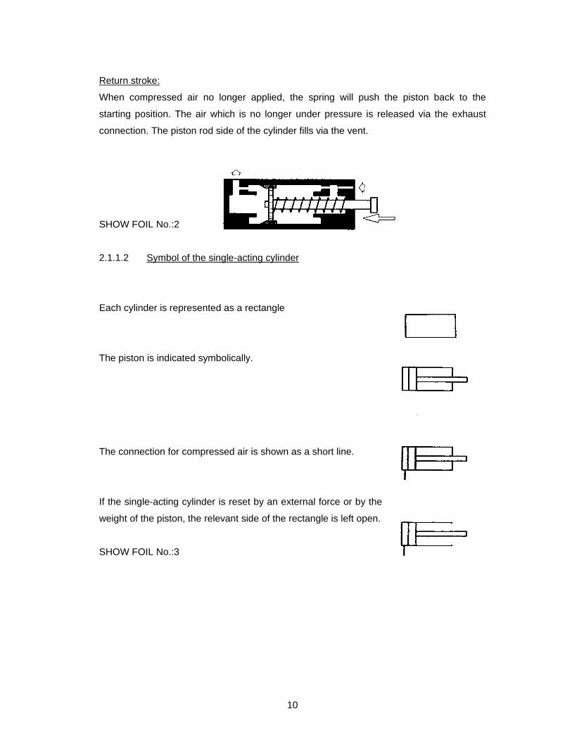
2.1.1.2 Symbol of the single-acting cylinder
Each cylinder is represented as a rectangle
The piston is indicated symbolically.
The connection for compressed air is shown as a short line.
If the single-acting cylinder is reset by an external force or by the
weight of the piston, the relevant side of the rectangle is left open.
SHOW FOIL No.:3
11
If the return movement is effected
by a spring it will be shown by a
symbol.
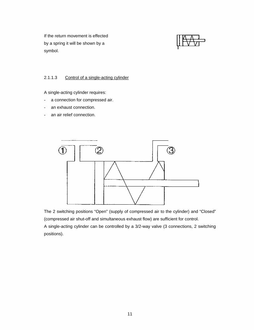
2.1.1.3 Control of a single-acting cylinder
A single-acting cylinder requires:
- a connection for compressed air.
- an exhaust connection.
- an air relief connection.
The 2 switching positions “Open” (supply of compressed air to the cylinder) and “Closed”
(compressed air shut-off and simultaneous exhaust flow) are sufficient for control.
A single-acting cylinder can be controlled by a 3/2-way valve (3 connections, 2 switching
positions).

12
2.1.1.4 Components of a single-acting cylinder
SHOW FOIL No.:4
Types of single-acting cylinders:
Piston cylinder
Diaphragm cylinder
Piston/diaphragm cylinder
2.1.2 Double-acting cylinders
Double-acting cylinders have two connections for the supply of compressed air. Work can
be performed in both directions as the advance as well as the return strokes are effected
by the compressed air.
air relief connection
compressed air connection
spring
piston rod
cylinder barrel with caps
scraper ring piston packing

13
2.1.2.1 Starting position
The piston is not under pressure and remains in its initial position.
Supply of compressed
air or air relief
SHOW FOIL No.:5
Working stroke 1 (advance stroke):
When compressed air is applied via the first connection, the piston is moved. The piston
rod moves out. The air on the piston rod side is vented via the second connection. When
the supply of compressed air is stopped, the piston remains in the advanced positions
until compressed air is again applied.
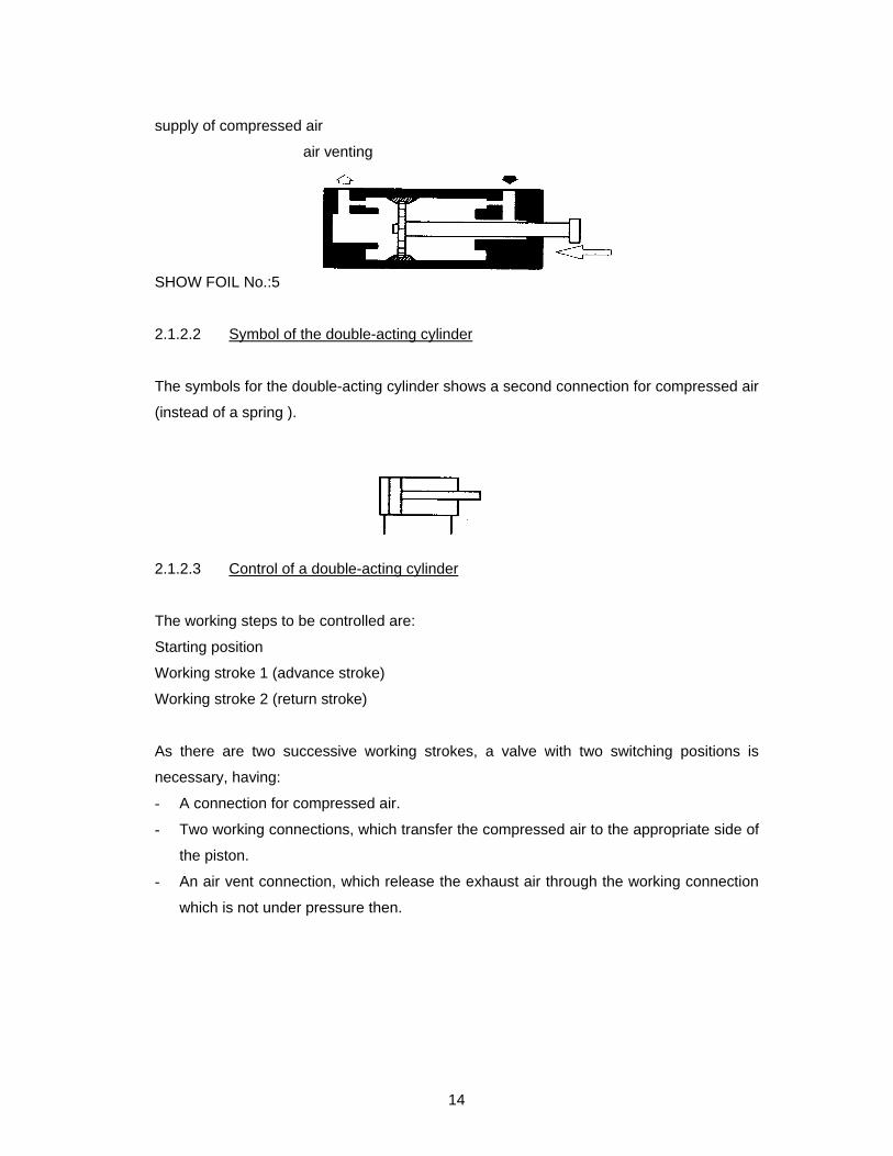
supply of compressed air
air venting
SHOW FOIL No.:5
Working stroke 2 (return stroke):
If compressed air is supplied again, this time via the second connection, the piston is
returned to the initial position. Air is vented via the first connection.
When the supply of compressed air is cut off, the piston remains in the start position.
14
supply of compressed air
air venting
SHOW FOIL No.:5
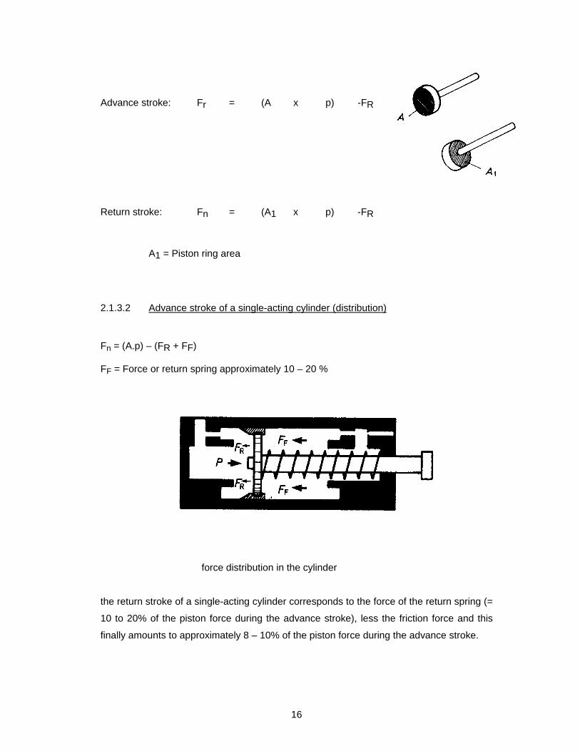
2.1.2.2 Symbol of the double-acting cylinder
The symbols for the double-acting cylinder shows a second connection for compressed air
(instead of a spring ).
2.1.2.3 Control of a double-acting cylinder
The working steps to be controlled are:
Starting position
Working stroke 1 (advance stroke)
Working stroke 2 (return stroke)
As there are two successive working strokes, a valve with two switching positions is
necessary, having:
- A connection for compressed air.
- Two working connections, which transfer the compressed air to the appropriate side of
the piston.
- An air vent connection, which release the exhaust air through the working connection
which is not under pressure then.

15
There is a total of four connections.
The two switching positions “A charged/B exhaust” and B charged/A exhaust” are
sufficient for control.
With a 4/2-way valve (4 connections, 2 switching positions)
A double-acting cylinder can be controlled.
2.1.2.4 Components of a double-acting controlled
SHOW FOIL No.:4
A double-acting cylinder can be used economically up to a diameter of 500 mm. The
potential length of the stroke us unlimited.
2.1.3 Calculations of force
2.1.3.1 Calculations for the piston force
Theoretical piston force: Fth = A x p
Area Pressure
Effective piston force: Fn = (A x p) -FR
Area Pressure-10%
Friction force
working connections
cylinder barrel with caps
piston rod
scraper ring packing
piston
16
Advance stroke: Fr = (A x p) -FR
Return stroke: Fn = (A1 x p) -FR
A1 = Piston ring area
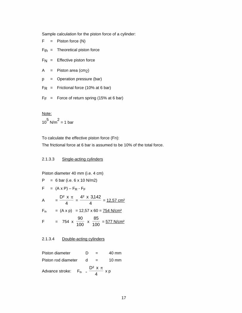
2.1.3.2 Advance stroke of a single-acting cylinder (distribution)
Fn = (A.p) – (FR + FF)
FF = Force or return spring approximately 10 – 20 %
force distribution in the cylinder
the return stroke of a single-acting cylinder corresponds to the force of the return spring (=
10 to 20% of the piston force during the advance stroke), less the friction force and this
finally amounts to approximately 8 – 10% of the piston force during the advance stroke.
4
x²D
17
Sample calculation for the piston force of a cylinder:
F = Piston force (N)
Fth = Theoretical piston force
FN = Effective piston force
A = Piston area (cm2)
p = Operation pressure (bar)
FR = Frictional force (10% at 6 bar)
FF = Force of return spring (15% at 6 bar)
Note:
105 N/m
2 = 1 bar
To calculate the effective piston force (Fn):
The frictional force at 6 bar is assumed to be 10% of the total force.
2.1.3.3 Single-acting cylinders
Piston diameter 40 mm (i.e. 4 cm)
P = 6 bar (i.e. 6 x 10 N/m2)
F = (A x P) – FR - FF
A = 4
x²D =
4
142,3x²4 = 12,57 cm²
Fth = (A x p) = 12,57 x 60 = 754 N/cm²
F = 754 x 100
90 x
100
85 = 577 N/cm²
2.1.3.4 Double-acting cylinders
Piston diameter D = 40 mm
Piston rod diameter d = 10 mm
Advance stroke: Fth = 4
x²D x p
18
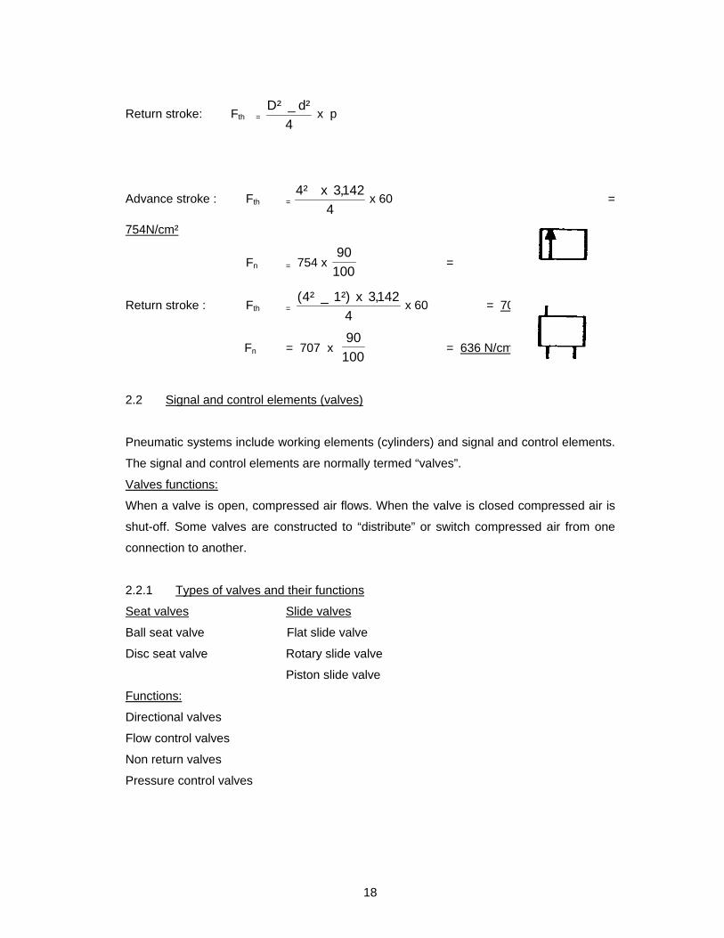
Return stroke: Fth = 4
²d_²D x p
Advance stroke : Fth = 4
142,3x²4 x 60 =
754N/cm²
Fn = 754 x 100
90 = 679 N/cm²
Return stroke : Fth = 4
142,3x²)1_²4( x 60 = 707 N/cm²
Fn = 707 x 100
90 = 636 N/cm²
2.2 Signal and control elements (valves)
Pneumatic systems include working elements (cylinders) and signal and control elements.
The signal and control elements are normally termed “valves”.
Valves functions:
When a valve is open, compressed air flows. When the valve is closed compressed air is
shut-off. Some valves are constructed to “distribute” or switch compressed air from one
connection to another.
2.2.1 Types of valves and their functions
Seat valves Slide valves
Ball seat valve Flat slide valve
Disc seat valve Rotary slide valve
Piston slide valve
Functions:
Directional valves
Flow control valves
Non return valves
Pressure control valves
19
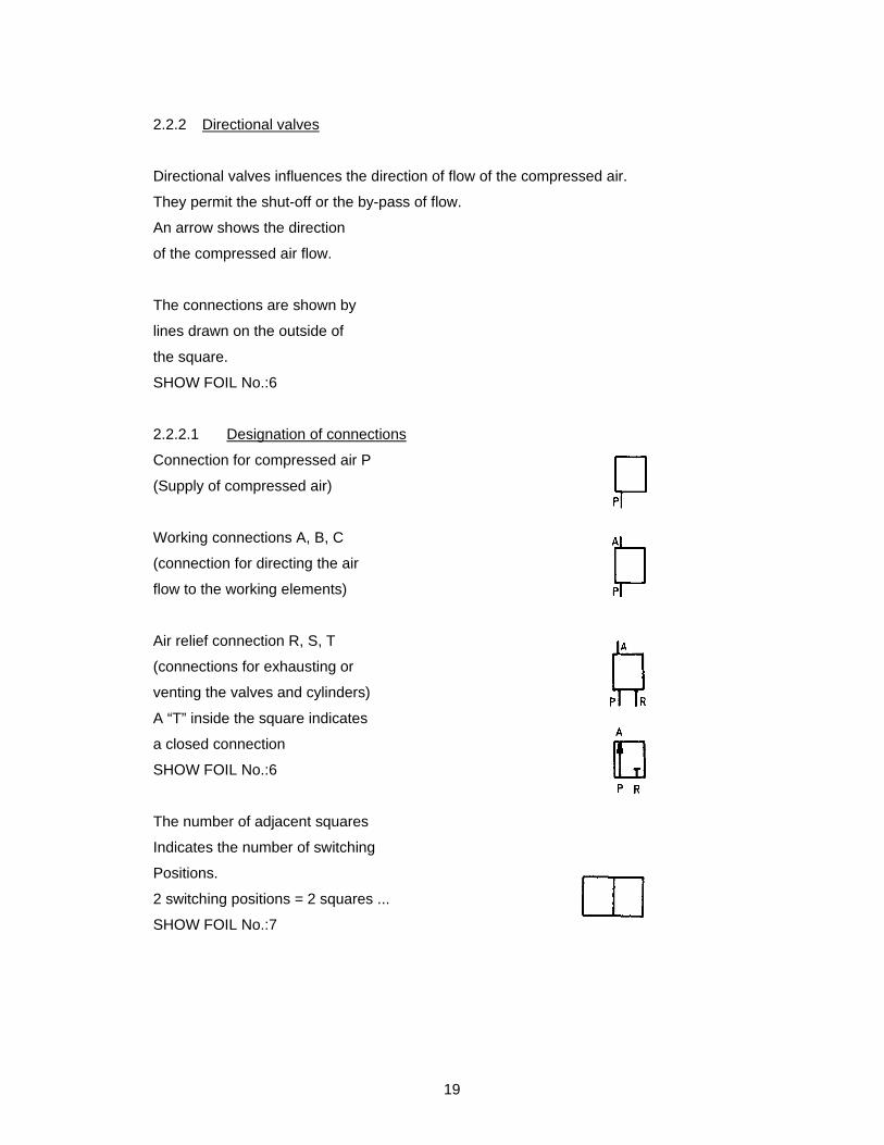
2.2.2 Directional valves
Directional valves influences the direction of flow of the compressed air.
They permit the shut-off or the by-pass of flow.
An arrow shows the direction
of the compressed air flow.
The connections are shown by
lines drawn on the outside of
the square.
SHOW FOIL No.:6
2.2.2.1 Designation of connections
Connection for compressed air P
(Supply of compressed air)
Working connections A, B, C
(connection for directing the air
flow to the working elements)
Air relief connection R, S, T
(connections for exhausting or
venting the valves and cylinders)
A “T” inside the square indicates
a closed connection
SHOW FOIL No.:6
The number of adjacent squares
Indicates the number of switching
Positions.
2 switching positions = 2 squares ...
SHOW FOIL No.:7
20
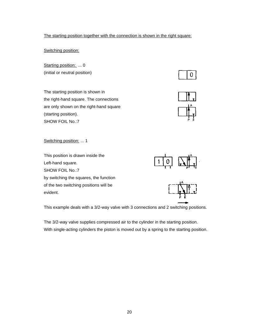
The starting position together with the connection is shown in the right square:
Switching position:
Starting position: ... 0
(initial or neutral position)
The starting position is shown in
the right-hand square. The connections
are only shown on the right-hand square
(starting position).
SHOW FOIL No.:7
Switching position: ... 1
This position is drawn inside the
Left-hand square.
SHOW FOIL No.:7
by switching the squares, the function
of the two switching positions will be
evident.
This example deals with a 3/2-way valve with 3 connections and 2 switching positions.
The 3/2-way valve supplies compressed air to the cylinder in the starting position.
With single-acting cylinders the piston is moved out by a spring to the starting position.

21
When compressed air is supplied to the 3/2-way valve shown, the return stroke is
effected.
If the energy fails or a control signal is received the piston is moved out again by the force
of the return spring.
The principle described is used for emergency braking systems on railways and lorries. If
the energy supply fails or an emergency signal is received, the supply of compressed air
is stopped and the brakes are applied.

22
2.2.2.2 Switching positions of directional valves
number of connections/switching positions
1 2 3 4 5 6 7 8
connections
position
compressed air
connections
working connection
air relief
connection
connections
2/2
shut-off
zero
1
1
2
3/2
flow
zero
1
1
1
3
3/3
shut-off
mid
1
1
3
4/2
1
2
1
4
4/3
1
2
1
4
4/3
1
2
1
4
5/2
1
2
2
5
5/3
1
2
2
5
switching positions 2 2 3 2 3 3 2 3
ao a
a o b o
b
Open
Shut-off
-
A
vented
A open
A open
Shut-off
A vented
B open
A vented
A open
B vented
-
B open
A vented
A+B
Shut-off
A open
B vented
B open
A vented
A+B
Vented
A open
B vented
A open
B-S vented
B open
A-R vented
-
A open
B-S vented
Shut-off
B open
A-R vented
Control connections (types of actuation) see page 29
Symbols:
SHOW FOIL No.:8
23
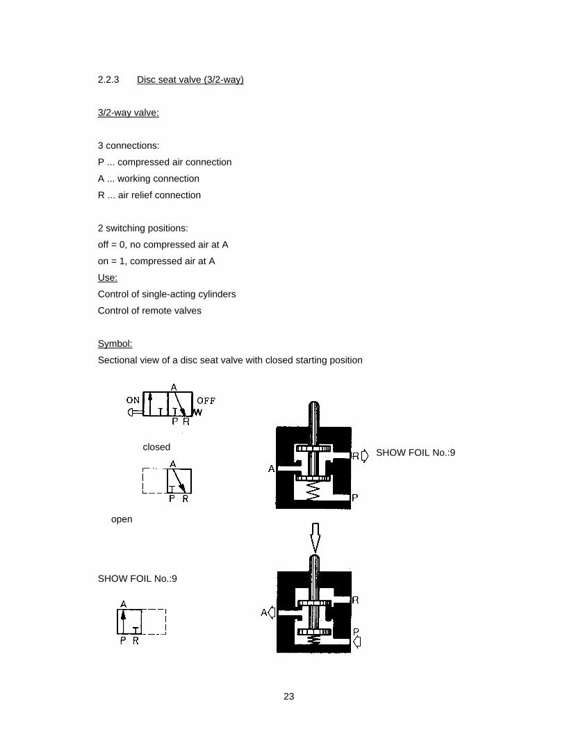
2.2.3 Disc seat valve (3/2-way)
3/2-way valve:
3 connections:
P ... compressed air connection
A ... working connection
R ... air relief connection
2 switching positions:
off = 0, no compressed air at A
on = 1, compressed air at A
Use:
Control of single-acting cylinders
Control of remote valves
Symbol:
Sectional view of a disc seat valve with closed starting position
SHOW FOIL No.:9
open
SHOW FOIL No.:9
closed
24
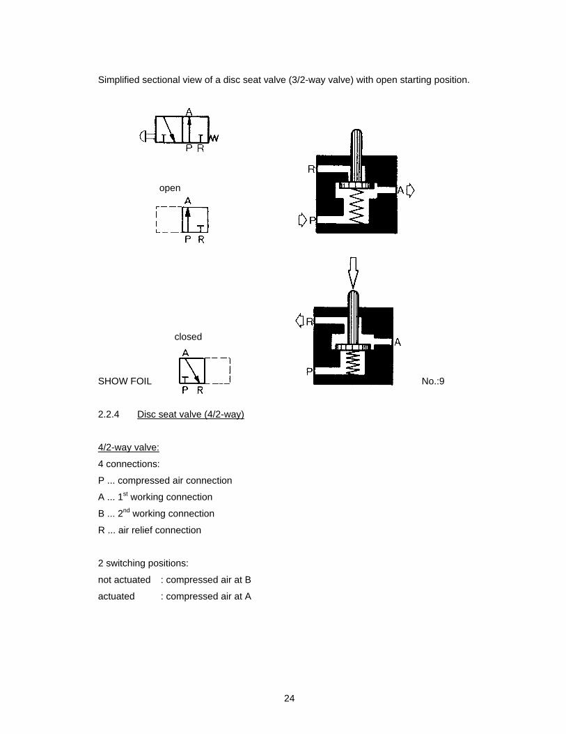
Simplified sectional view of a disc seat valve (3/2-way valve) with open starting position.
SHOW FOIL No.:9
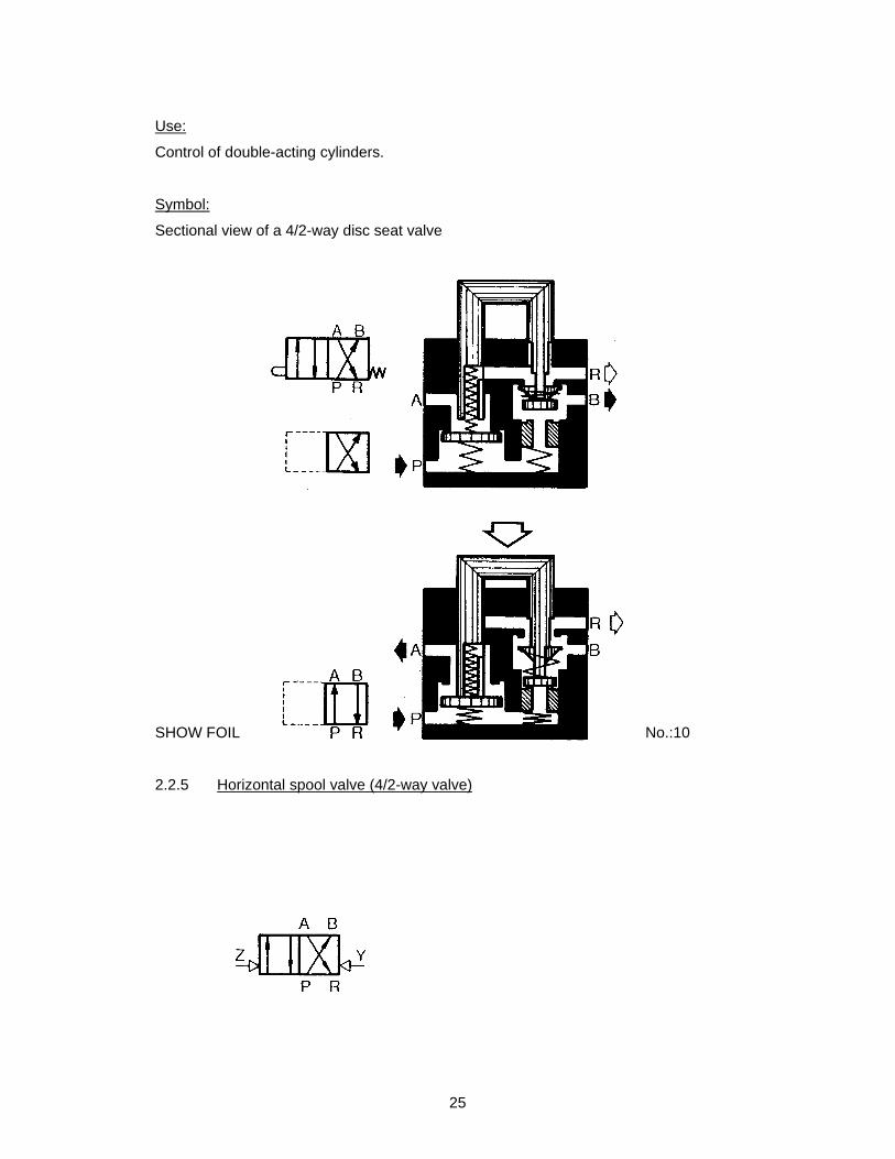
2.2.4 Disc seat valve (4/2-way)
4/2-way valve:
4 connections:
P ... compressed air connection
A ... 1st working connection
B ... 2nd working connection
R ... air relief connection
2 switching positions:
not actuated : compressed air at B
actuated : compressed air at A
open
closed
25
Use:
Control of double-acting cylinders.
Symbol:
Sectional view of a 4/2-way disc seat valve
SHOW FOIL No.:10
2.2.5 Horizontal spool valve (4/2-way valve)
26
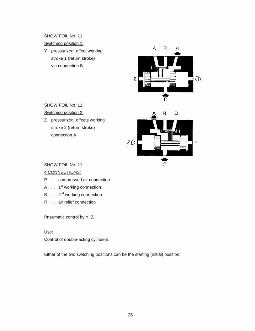
SHOW FOIL No.:11
Switching position 1:
Y pressurized; effect working
stroke 1 (return stroke)
via connection B
SHOW FOIL No.:11
Switching position 2:
Z pressurized; effects working
stroke 2 (return stroke)
connection A
SHOW FOIL No.:11
4 CONNECTIONS:
P ... compressed air connection
A ... 1st working connection
B ... 2nd working connection
R ... air relief connection
Pneumatic control by Y, Z.
Use:
Control of double-acting cylinders.
Either of the two switching positions can be the starting (initial) position.
27
2.2.6 Actuation of a valve
How a valve is switched over:
In the practical application of pneumatic control systems, valves may be actuated
independantly of the pneumatic system, or their action may be initiated by piston
movement.
Types of valve actuation:
Manual actuation
Mechanical actuation
Electrical actuation
Pressure actuation (direct or indirect)
Combined actuation
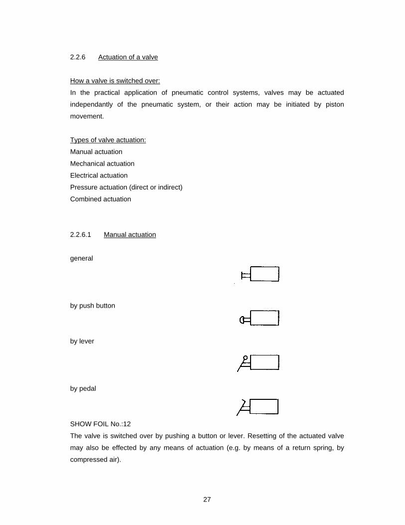
2.2.6.1 Manual actuation
general
by push button
by lever
by pedal
SHOW FOIL No.:12
The valve is switched over by pushing a button or lever. Resetting of the actuated valve
may also be effected by any means of actuation (e.g. by means of a return spring, by
compressed air).
28
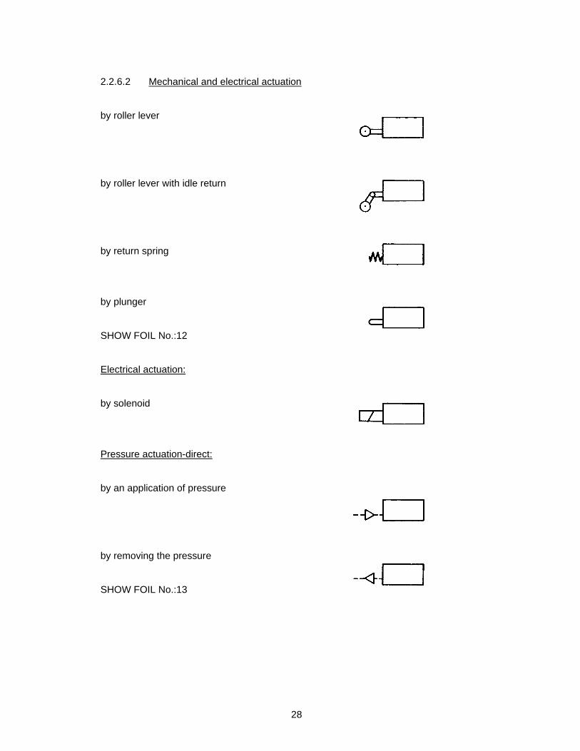
2.2.6.2 Mechanical and electrical actuation
by roller lever
by roller lever with idle return
by return spring
by plunger
SHOW FOIL No.:12
Electrical actuation:
by solenoid
Pressure actuation-direct:
by an application of pressure
by removing the pressure
SHOW FOIL No.:13
29
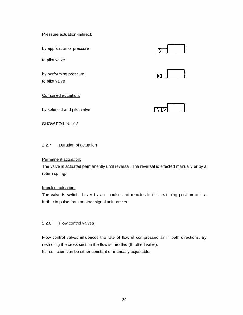
Pressure actuation-indirect:
by application of pressure
to pilot valve
by performing pressure
to pilot valve
Combined actuation:
by solenoid and pilot valve
SHOW FOIL No.:13
2.2.7 Duration of actuation
Permanent actuation:
The valve is actuated permanently until reversal. The reversal is effected manually or by a
return spring.
Impulse actuation:
The valve is switched-over by an impulse and remains in this switching position until a
further impulse from another signal unit arrives.
2.2.8 Flow control valves
Flow control valves influences the rate of flow of compressed air in both directions. By
restricting the cross section the flow is throttled (throttled valve).
Its restriction can be either constant or manually adjustable.

30
Throttle valve:
SHOW FOIL No.:14
2.2.9 Non-return valves
These allow the flow of air in one direction.
The flow in the opposite direction is stopped.
Check valve:
free flow return direction
SHOW FOIL No.:14
When compressed air flows from the return direction, the valve is closed.
2.2.10 Throttle relief valve
The throttle relief valve represents a combination of a flow control and a non-return valve.
It is included with the group of non-return valves.
throttle flow free flow
SHOW FOIL No.:14
The throttle relief valve has an adjustable throat which controls the flow in one direction
thus regulating the control sequences.
constant adjustable
31
Throttle relief valves are used:
- for regulating the piston speed with single or double-acting cylinders.
- for regulating the fill time of a delay valve.
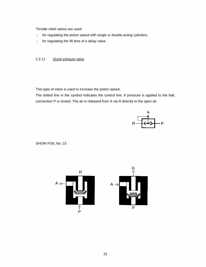
2.2.11 Quick-exhaust valve
This type of valve is used to increase the piston speed.
The dotted line in the symbol indicates the control line. If pressure is applied to the ball,
connection P is closed. The air is released from A via R directly to the open air.
SHOW FOIL No.:15

32
2.2.11.1 Quick-exhaust valve with volume control reservoir
This is used for cleaning off shavings from workpieces and swarf from machine tools.
SHOW FOIL NO.:15
2.2.12 Shuttle valve (OR-function)
This used if control is to be effected from either of two geographically separated positions.
If a cylinder or control valve is to be actuated from two or several positions (e.g. by hand
or foot), a shuttle valve should be used.
The shuttle valve has a so-called OR-function (OR-valve).
SHOW
FOIL
No.:16

33
2.2.13 Two pressure valve (AND-function)
If for safety precaution interlocking controls or check functions have to be installed, the
best way for doing this is by using the two pressure valve.
For operating a press, two levers, which are at a double arm’s length apart, have to be
actuated simultaneously in order to prevent the operator from getting his hand caught in
the press.
SHOW FOIL No.:17
If only one of the two compressed air connections is pressurized the valve remains
closed. Compressed air does not flow to the working connection until the other
compressed air connection is also pressurized. Both positions have to be actuated
simultaneously. This valve has a so-called AND-function (AND-valve).
A two pressure valve can be replaced:
- by two 3/2-way valves connected in sequences
- by one 3/2-way valve and one 2/2-way valve via an impulse controlled 3/2-way valve.
2.2.14 Other types of valves
In additional to the valves already mentioned, there are also pressure controlled valves,
which determine the air pressure. Furthermore there are valve combinations, such as the
“time delay valve”.

34
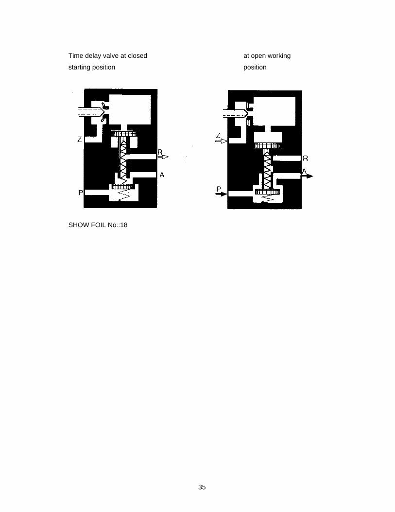
Time delay valve:
This type of valve is composed of a pneumatically actuated 3/2-way valve, a throttle relief
valve and an air container.
The pilot air flows from inlet Z to the throttle relief valve and from there to the air container.
The latter is filled at a greater or lesser speed according to the throttle adjustment (usually
within 1 to 30 seconds). When the necessary control pressure has been reached the 3/2-
way valve switched into position 1 and P-A opens.
With the release of the control line air, the valve switches into position O owing to the
effect of the return spring.
With clean air, an accurate time of switching may be achieved, but dust has a detrimental
effect.
Time delay valves are used:
- to limit operational sequences by time (cylinder).
- for delayed switching of valves.
35
Time delay valve at closed at open working
starting position position
SHOW FOIL No.:18
36
3 SYSTEMS OF CONTROL
To facilitate the understanding of control systems, circuit diagrams and phase diagrams
are made, which describe the system and the operation briefly but exactly.
3.1 Circuit diagrams
Circuit diagrams have been standardized according to DIN 24300. This standardization
refers to the symbols as well as to the graphic representation of compete circuits.
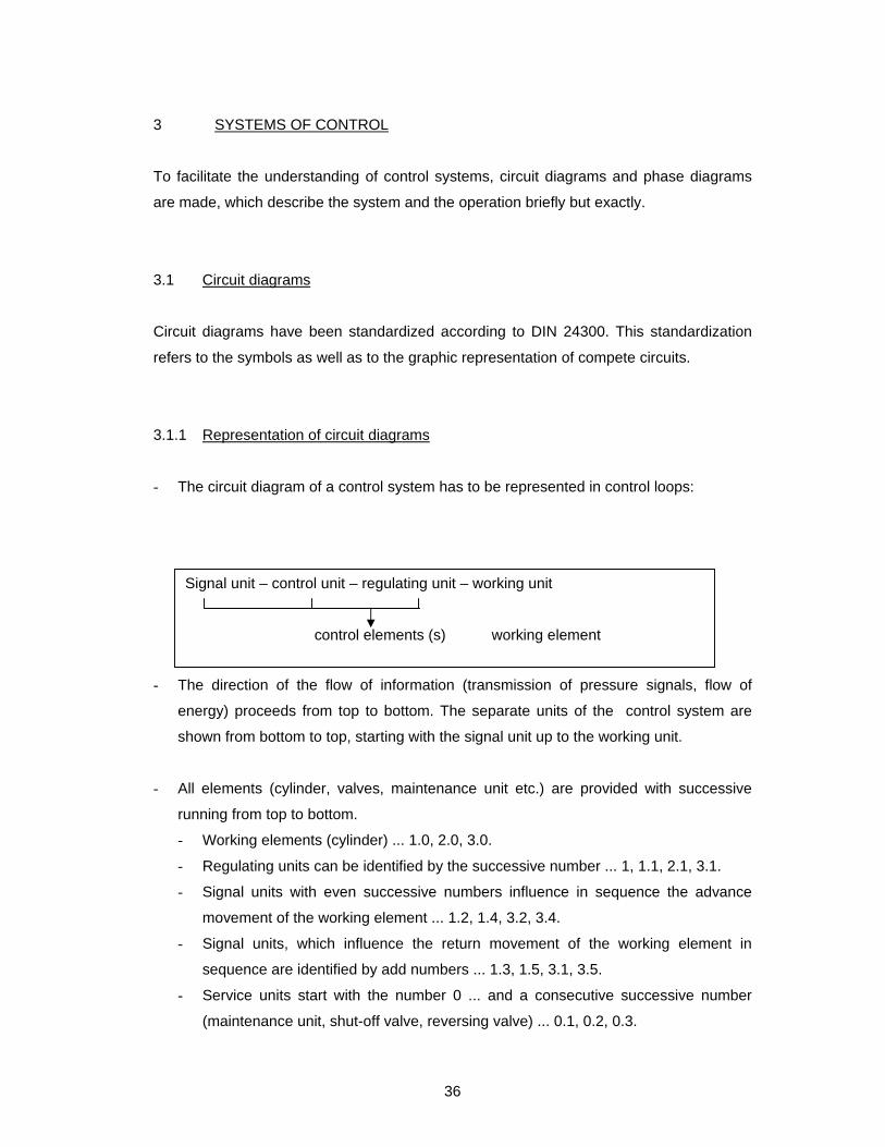
3.1.1 Representation of circuit diagrams
- The circuit diagram of a control system has to be represented in control loops:
- The direction of the flow of information (transmission of pressure signals, flow of
energy) proceeds from top to bottom. The separate units of the control system are
shown from bottom to top, starting with the signal unit up to the working unit.
- All elements (cylinder, valves, maintenance unit etc.) are provided with successive
running from top to bottom.
- Working elements (cylinder) ... 1.0, 2.0, 3.0.
- Regulating units can be identified by the successive number ... 1, 1.1, 2.1, 3.1.
- Signal units with even successive numbers influence in sequence the advance
movement of the working element ... 1.2, 1.4, 3.2, 3.4.
- Signal units, which influence the return movement of the working element in
sequence are identified by add numbers ... 1.3, 1.5, 3.1, 3.5.
- Service units start with the number 0 ... and a consecutive successive number
(maintenance unit, shut-off valve, reversing valve) ... 0.1, 0.2, 0.3.
Signal unit – control unit – regulating unit – working unit control elements (s) working element

37
- Additional devices, such as throttle relief valve, throttle and quick exhaust fan are
given a zero preceding the successive number (e.g. 1.02). the prefix number
identifies the working element to be influenced (e.g. cylinder 1.0) ... 1.02, 1.03, 3.0.
3.1.2 Numerical notation
Each working element (cylinder) is given a number, e.g. 1.0 or 2.0 or 3.0.
The control element preceding the cylinder 1.0 gets the successive number 1.1. if a
further control element (control unit) precedes this control element (regulating unit), it will
be shown by the successive number 1.2, etc.
Thus control elements of the cylinder 2.0 are shown by the corresponding successive
numbers 2.1, 2.2, 2.3 etc.
Working element 1
Control elements
for the working element 1
SHOW FOIL No.:19

38
Working element 2
Control elements for working
elements 2
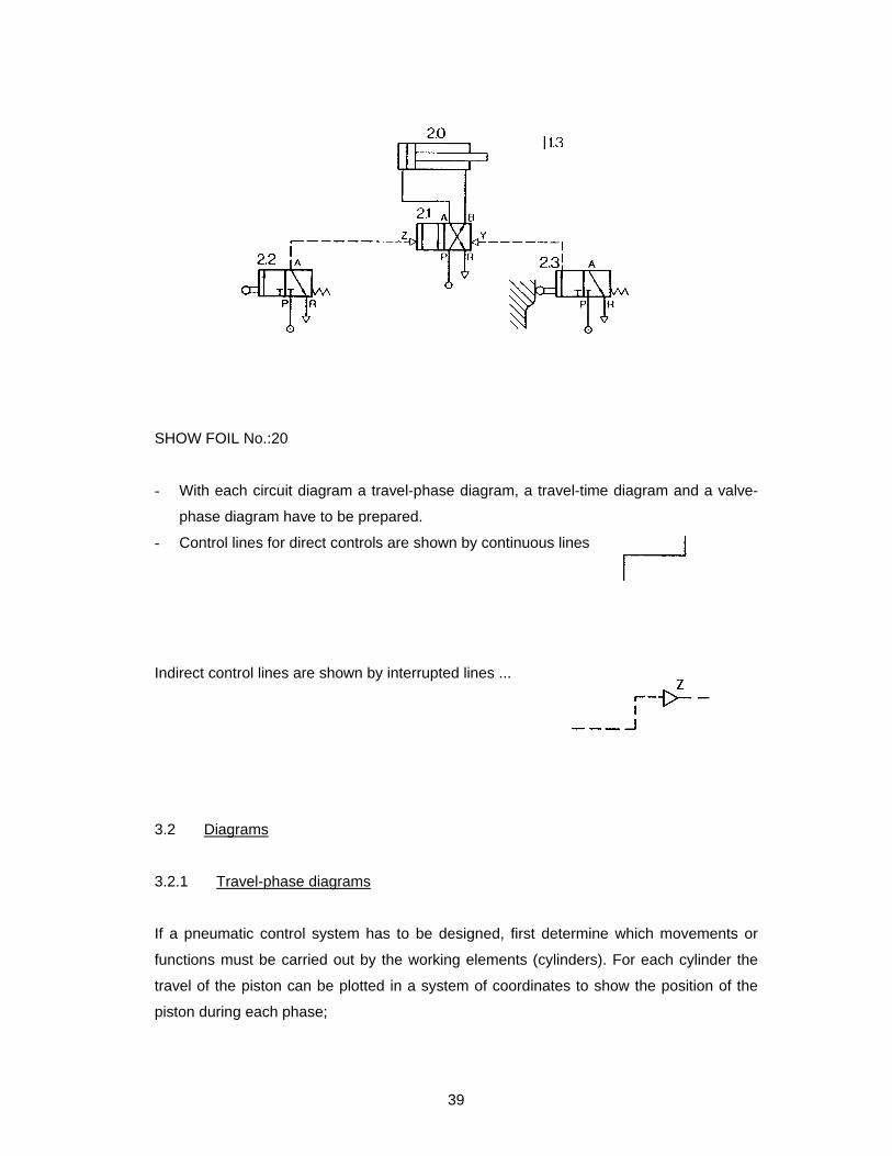
3.1.3 Drawing conventions
- All cylinders and valves are drawn in the starting position (initial position).
- Valves are shown in the horizontal position.
- The actual position of the valves is indicated by lines across the piston rod, together
with the serial number of the valve to be actuated, in the case of mechanic actuation.
SHOW FOIL No.:20
39
SHOW FOIL No.:20
- With each circuit diagram a travel-phase diagram, a travel-time diagram and a valve-
phase diagram have to be prepared.
- Control lines for direct controls are shown by continuous lines
Indirect control lines are shown by interrupted lines ...
3.2 Diagrams
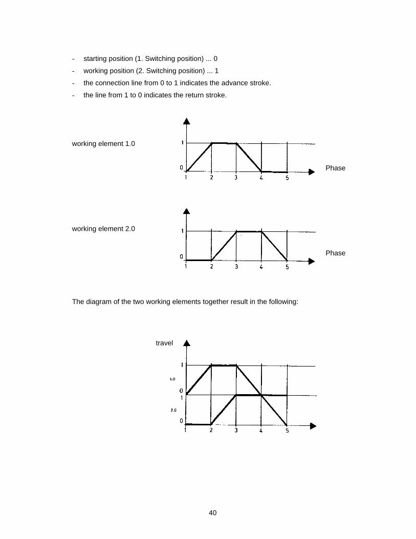
3.2.1 Travel-phase diagrams
If a pneumatic control system has to be designed, first determine which movements or
functions must be carried out by the working elements (cylinders). For each cylinder the
travel of the piston can be plotted in a system of coordinates to show the position of the
piston during each phase;
40
- starting position (1. Switching position) ... 0
- working position (2. Switching position) ... 1
- the connection line from 0 to 1 indicates the advance stroke.
- the line from 1 to 0 indicates the return stroke.
working element 1.0
Phase
working element 2.0
Phase
The diagram of the two working elements together result in the following:
travel

41
3.2.2 Travel-time diagrams
The travel-phase diagram gives no information about the duration of the single steps. The
travel-time diagram shows the duration (of each phase) in seconds together with the travel
(0/1).
SHOW FOIL No.:21
3.2.3 Valve-phase diagrams
The switching positions and the impulses given by the valves can also be clearly
represented in a diagram:
The switching position of the control unit are plotted for each phase (control diagram).
travel
duration in sec
phases
valve
phases

42
The best survey is obtained by showing the travel-phase and valve-phase diagram
together:
Phase
Cylinder 1.0
Cylinder 2.0
Regulating unit 1.1
Regulating unit 2.1
Regulating unit 1.2
Regulating unit 1.3
Regulating unit 2.2
Regulating unit 2.3
SHOW FOIL No.:21
43
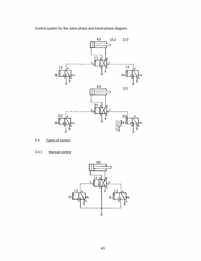
Control system for the valve-phase and travel-phase diagram.
3.3 Types of control
3.3.1 Manual control

44
Manually actuated valves are used.
For short switching impulses valves are used with a spring return mechanism. Return
springs are not used for long impulses.
3.3.2 Travel control
Two 3/2-way valves (signal units) alternatively operate a 4/2-way valve (regulating unit).
After application of compressed air an automatic control sequence proceeds, depending
on the position of the cylinder or depending on the stroke (travel) last executed.
3.3.3 Manual and travel control
45
The advance stroke is initiated manually. When the piston has moved out fully, it
automatically gives the impulse for the return stroke.
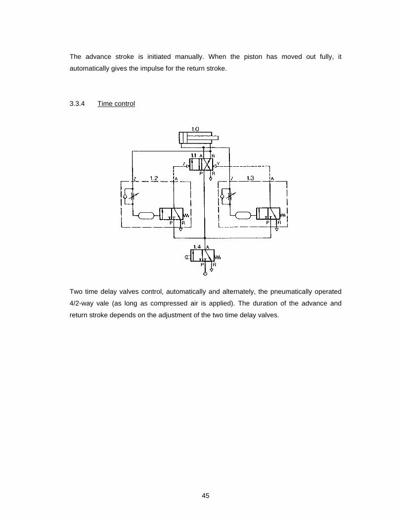
3.3.4 Time control
Two time delay valves control, automatically and alternately, the pneumatically operated
4/2-way vale (as long as compressed air is applied). The duration of the advance and
return stroke depends on the adjustment of the two time delay valves.

46
3.3.5 Manual and time control
The advance stroke is started by a manually actuated 3/2-way valve.
The return stroke is effected automatically by a time delay valve with adjustable delay.
Application of pneumatic controls:
Pneumatics are widely used in nearly all branches of industry for linear movements,
swivelling movements and rotary movements when:
Metal cutting
milling, turning, drilling, sawing, reaming.
Metal forming
bending, edging, forging, deep-drawing.
Assembling
lifting, riveting, screwing, clamping, pressing
47
4. COMPRESSORS
Compressors of different types are used for producing compressed air.
For larger industrial plants central installations are usually built and the compressed air is
then supplied to the consumers by distribution systems. To ensure long and satisfactory
service, it is of great importance to have clean air available.
4.1 Types of compressors
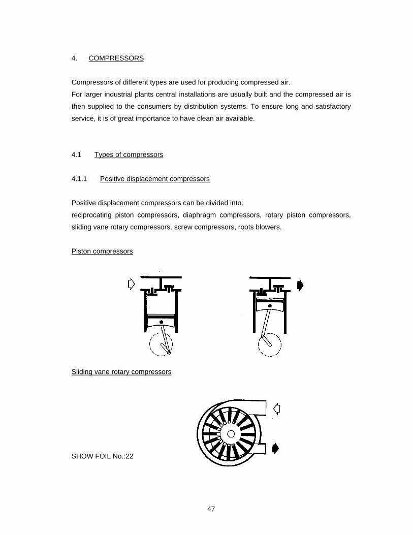
4.1.1 Positive displacement compressors
Positive displacement compressors can be divided into:
reciprocating piston compressors, diaphragm compressors, rotary piston compressors,
sliding vane rotary compressors, screw compressors, roots blowers.
Piston compressors
Sliding vane rotary compressors
SHOW FOIL No.:22
48
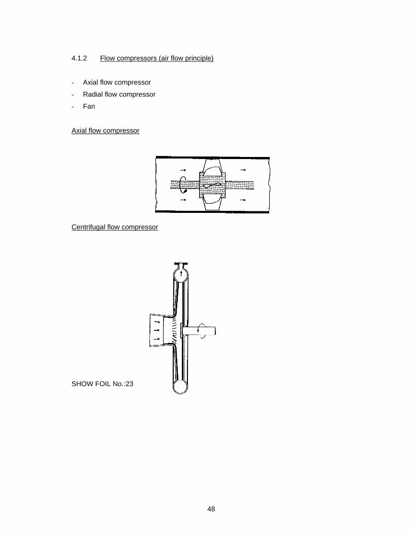
4.1.2 Flow compressors (air flow principle)
- Axial flow compressor
- Radial flow compressor
- Fan
Axial flow compressor
Centrifugal flow compressor
SHOW FOIL No.:23
49
4.1.3 Pressure and delivery volumes of compressor types
Piston compressor up to 1000 bar and up to 10.000 m3/h.
Radial flow compressors up to 300 bar and up to 200.000 m3/h.
Axial flow up to 4 bar and up to 500.000 m3/h.
Screw compressor up to 25 bar and up to 50.000 m3/h.
Slide vane rotary compressor up to 9 bar and up to 15.000 m3/h.
4.2 Regulation of compressors
No-load regulation
Exhaust regulation:
When the pressure has reached the set value the compressed air is exhaust into the
atmosphere thorough a safety valve.
Shut-off regulation:
When maximum pressure is reached the suction of the compressor is shut-off and
continues to run under vacuum.
Low-speed regulation:
Speed regulation:
When the maximum pressure is reached, the speed of the compressor is controlled
through a speed regulator either manually or automatically.
On-off regulation:
The drive motor of the compressor is switched off on reaching maximum pressure. When
the pressure has dropped to a predetermine minimum the motor is switched on again.
50
5. MAINTENANCE OF PNEUMATIC INSTALLATIONS
Maintenance should not be limited to repair work.
Maintenance should be preventive in order to minimize possible damage to installation.
By maintaining equipment properly its working life can be prolonged and the shutdown
periods can be considerably reduced.
Maintenance manuals are issued by each supplier of pneumatic equipment for products
concerned.
They should always be carefully followed.
5.1 Maintenance
Well trained maintenance personnel are of great importance in order to keep costs for
repair work as low as possible.
Maintenance is divided into daily, weekly, monthly and annual maintenance procedures.
5.1.1 Daily maintenance
- Drain the condensate.
- Check the oil level in the oiler.
- Check the lubricating points.
5.1.2 Weekly maintenance
- Check and clean the signal units.
- Check the hoses.
- Check the union joints hoses for air tightness.
- Check the operation of the oiler.
- Check the manometer and pressure regulator.

51
5.1.3 Monthly maintenance
- Check all fixed screw connections for leakage.
- Check valves in 0-position for air leakage.
- Wash out filters.
- Recheck pipe connections on cylinder and float valves.
5.1.4 Annual maintenance
- Check cylinders, change worn parts, if necessary.
- Check equipment components for operation and efficiency.
- Replace filter and sound absorber inserts.
52
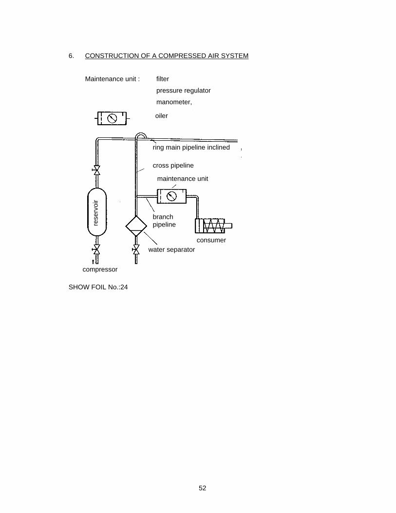
6. CONSTRUCTION OF A COMPRESSED AIR SYSTEM
Maintenance unit : filter
pressure regulator
manometer,
SHOW FOIL No.:24
ring main pipeline inclined
cross pipeline
maintenance unit
branch pipeline
consumer
water separator
rese
rvo
ir
oiler
compressor

53
Correct pressure limitation in a pneumatic system
SHOW FOIL No.:25
maintenance unit
reservoir with water separator
pressure relief valve check valve cooler compressor filter
drive motor
pressure operated electric switch
54
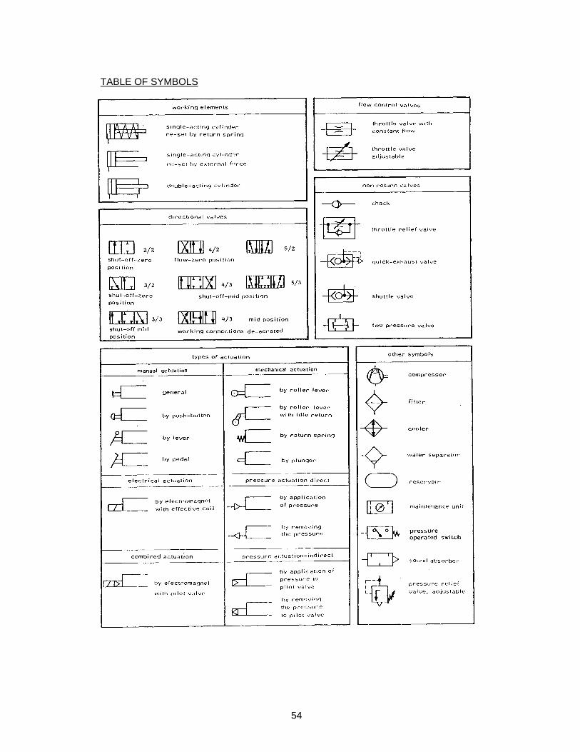
TABLE OF SYMBOLS
55
EE051 - Pneumatic
Theoretical Test

56
PNEUMATIC
TEST 1
1. At what speed do the pistons in pneumatic cylinders normally operate?
2. In special cases what speeds can be reached?
How is it achieved?
3. Why is there no danger of combustive explosion in pneumatic plants?
4. What are the three most important disadvantage of pneumatics?
5. Which gases is air composed of?
6. Draw a sectional view of a double-acting cylinder.
7. Name the constructional elements differ in single and double-acting cylinders.
8. Draw the circuit diagram for the control system of a single-acting cylinder with a 3/2-
way valve.
9. Which type of valve should be used for the control of a double-acting cylinder?
10. Draw the circuit diagram of the control system for a double-acting cylinder, fully
controlled by an appropriate valve.

57
PNEUMATIC
TEST 2
1. Calculate the effective force available for the advance stroke in a singe-acting
cylinder.
Basic date:
piston diameter : = 50 mm
working pressure: = 6 bar
2. State three types of actuation.
3. Name three types of valve actuation each, for manual and for mechanical actuation.
4. Explain the principle of flow control valves.
5. Draw a simplified sectional view of a throttle relief valve.
6. What is a quick-exhaust valve used for?
7. Explain the difference between a shuttle valve and a two pressure valve.
8. State the elements of a daily maintenance schedule.
9. State the elements of weekly maintenance schedule.
10. State the elements of a annual maintenance schedule.
58
PNEUMATIC
TEST 1
(Solution)
1. The working speed of a pneumatic piston amounts to 1-2 m/sec.
2. In special cylinders a working speed of 10 m/sec can be realised by fitting a quick
exhaust valve.
3. The gases used (air) in pneumatic plants are not liable to explosion.
4. The three disadvantages are:
- Air absorbs moisture.
- The noise of the exhaust air must be reduced by sound absorbers.
- The air pressure in a compressed air system is limited.
5. Air is a mixture of nitrogen, oxygen, hydrogen, helium, argon, krypton, neon and
xenon.
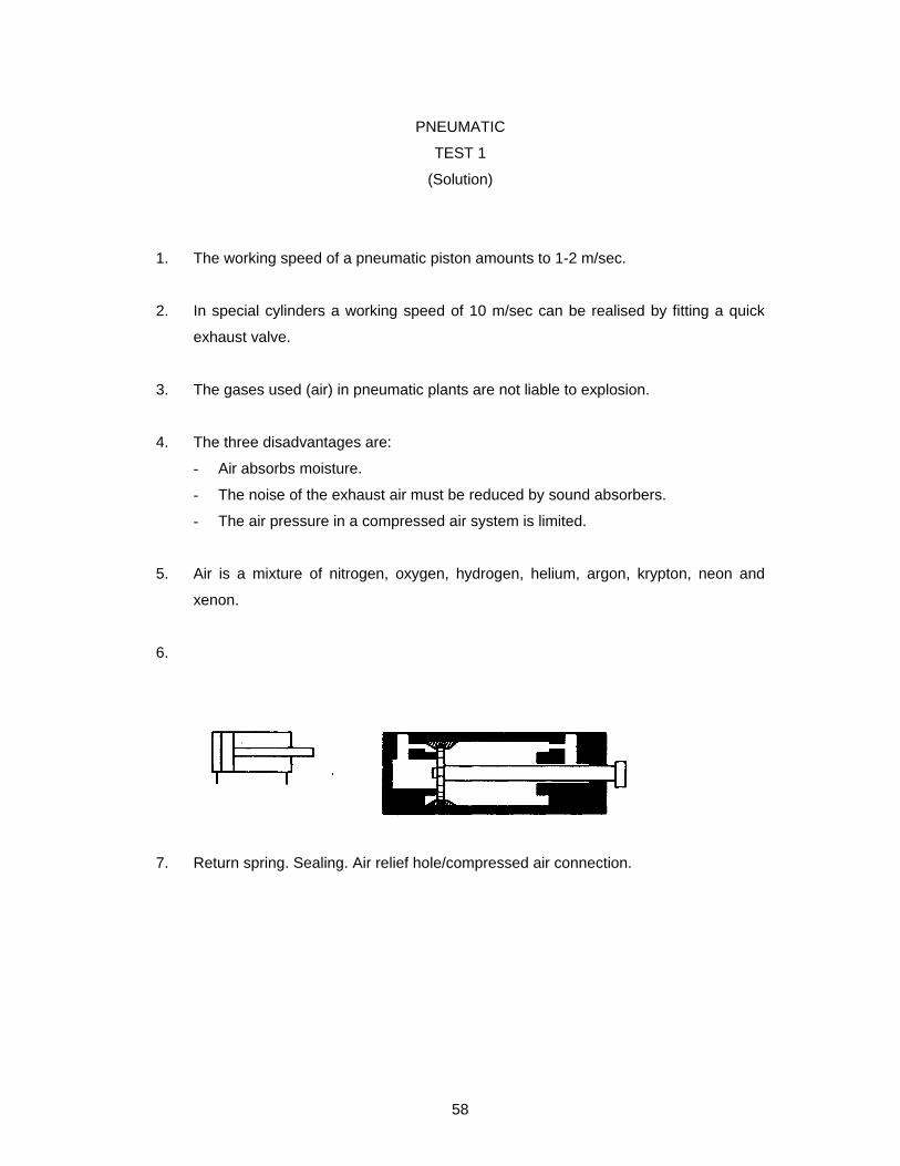
6.
7. Return spring. Sealing. Air relief hole/compressed air connection.

59
8.
9. For the control of a double-acting cylinder a 4/2-way valve is necessary.
10.

60
PNEUMATIC
TEST 2
(Solution)
1. Fn = 4
x²D x p - FR - FF
= 4
14,3x²5 x 6 x 10 - 25 % = 883,57 N/cm²
FR = 10%
FF = ~ 15 %
2. Types of actuation:
manual, mechanical, electrical, pneumatical, combined.
3. Types of actuation:
Manual actuation:
general, push button, lever, pedal.
Mechanical actuation:
roller lever, roller lever with idle return, spring plunger.
4. Flow control valves throttle the flow of compressed air through a restriction of the
cross section.
5.
6. A quick exhaust valve is used
for accelerating the piston stroke.
Advance as well as return stroke can be accelerated.

61
7. A shuttle valve enables a valve to be actuated from two different positions. The valve
can be controlled either from one position or form a second position (OR-valve).
The two pressure valve has to be actuated from two different positions. Compressed
air flows through only if signals arrive at both inlets (AND-valve).
8. Drain condensate.
Check oil-level.
Check lubrication points.
9. Check and clean signal units.
Check hoses.
Check unions and joints for tightness.
Check the operation of the oiler.
Check the manometer and pressure regulator.
10. Check cylinders-change worn parts.
Check operating efficiency.
Replace filters and sound absorbers/baffles.
62
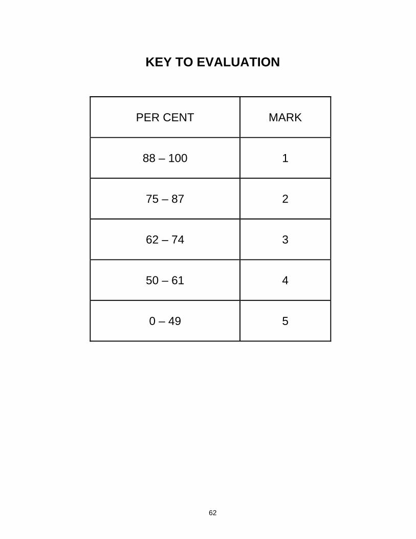
KEY TO EVALUATION
PER CENT
MARK
88 – 100
1
75 – 87
2
62 – 74
3
50 – 61
4
0 – 49
5