

EE 587 SoC Design & Test
24
1 EE 587 SoC Design & Test Partha Pande School of EECS Washington State University [email protected]
-
Upload
aurelia-evans -
Category
Documents
-
view
26 -
download
2
description
EE 587 SoC Design & Test. Partha Pande School of EECS Washington State University [email protected]. Design of Low Power SoC. Design Issues. SoCs contain several different cores like processors, memories etc Need of low power architectures Parallel architectures are less power hungry - PowerPoint PPT Presentation
Transcript of EE 587 SoC Design & Test

2
Design of Low Power SoC

3
Design Issues
• SoCs contain several different cores like processors, memories etc
• Need of low power architectures• Parallel architectures are less power hungry• Use of specialized and reconfigurable cores could improve
performance in such a way that supply voltage could be reduced resulting in lower power consumption
• Using a very dedicated co-processor to a given task could improve the speed/power performances of several orders of magnitude
4
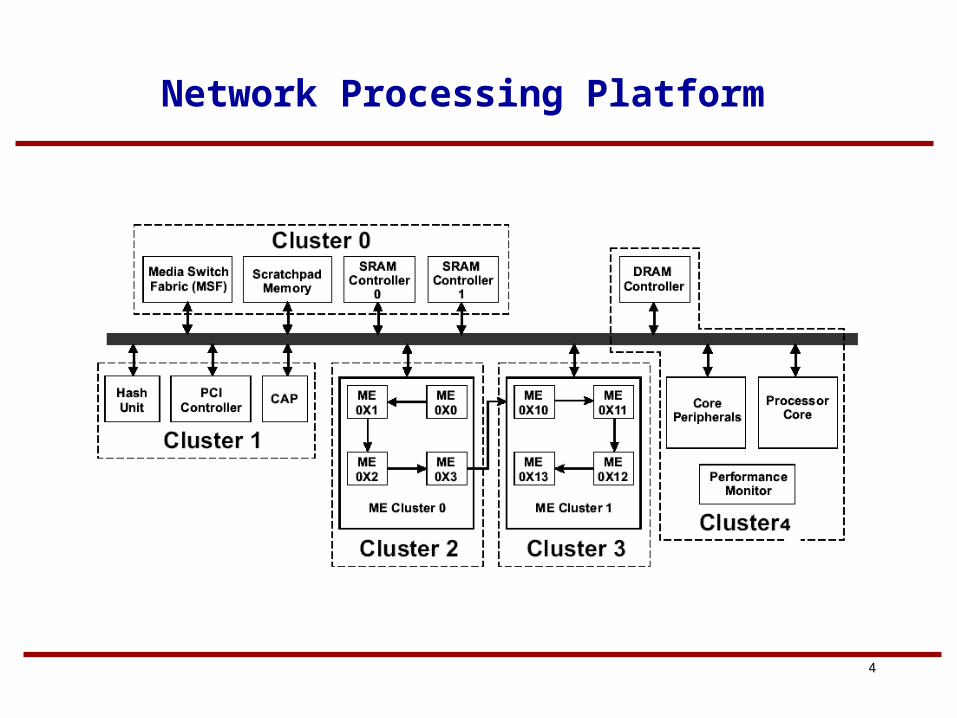
Network Processing Platform

5
Clock Distribution
clock
Clock consumes about 40% of total processor power.
6
Multiple Clock Domains
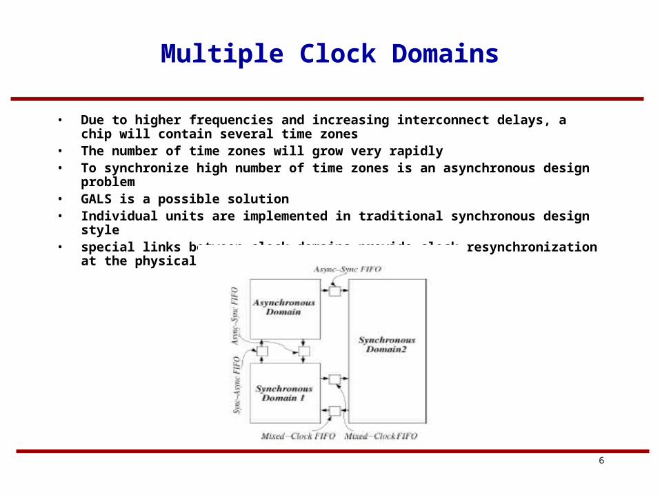
• Due to higher frequencies and increasing interconnect delays, a chip will contain several time zones
• The number of time zones will grow very rapidly• To synchronize high number of time zones is an asynchronous design problem• GALS is a possible solution• Individual units are implemented in traditional synchronous design style• special links between clock domains provide clock resynchronization at the physical
layer,

7
FIFO Interfaces

8
GasP Scheme

9
Architectural level issues
• Power and Vdd management• Low power communication protocols between the various IP
blocks• These protocols have to be simple and will be asynchronous in
nature

10
Dynamic Power Management
• Dynamically reconfigures an electronic system to provide the requested services and performance levels with a minimum number of active components or a minimum load on such components
• Selectively turns off or reduce the performance of idle or partially unexploited components
11
Power Management Example
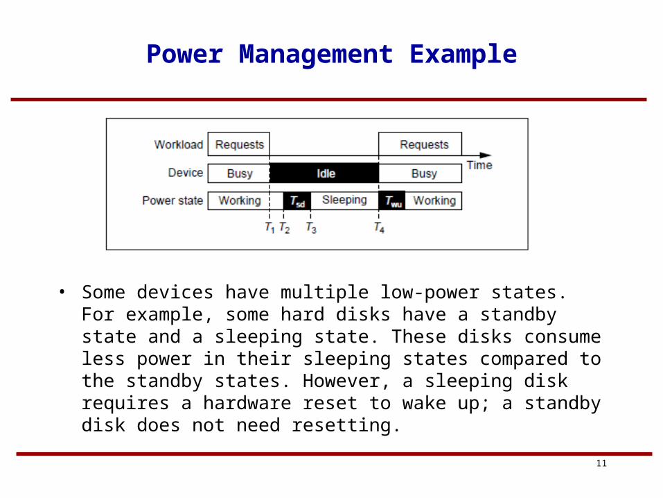
• Some devices have multiple low-power states. For example, some hard disks have a standby state and a sleeping state. These disks consume less power in their sleeping states compared to the standby states. However, a sleeping disk requires a hardware reset to wake up; a standby disk does not need resetting.
12
DPM Techniques
• Predictive Techniques– Exploit the correlation between the past history of the
workload and its near future– Should minimize the number of mispredictions– Over predictions give rise to performance penalty– Under predictions lead to power waste but no performance
penalty

13
Predictive Techniques
• A nonlinear regression equation is obtained from the past history is used to make predictions
11 ,..,,........., knidle
knactive
nidle
nactivepred TTTTT
• The power manager performs predictive wakeup when the predicted idle time expires

14
Static Techniques
• Fixed Timeout– When an idle period begins, a timer is started with duration
T0. If after this time the system is still idle, the PM forces it to the off state
– The system remains off until it receives a request from the environment that signals the end of the idle period
– Safety of these policies can be improved by just increasing the timeout values
– This might lead to large number of under predictions– Missed opportunity of saving power
15
Adaptive Techniques
• Workload statistics– a set of timeout values is maintained and each timeout is
associated with an index indicating how successful it would have been. The policy chooses, at each idle time, the timeout that would have performed best among the set of available ones.
– keep a list of candidate timeouts and assigns a weight to each timeout based on how well it would have performed relatively to an optimum offline strategy for past requests. The actual timeout is obtained as a weighted average of all candidates with their weights.

16
Implementation of DPM
• Clock Gating– Power can be saved by reducing the clock frequency (and in
the limit by stopping the clock), or by reducing the supply voltage (and in the limit by powering off a component)
– For components that are in an active state but whose response is not performance critical, power consumption can be traded off for performance by reducing the clock frequency or the supply voltage.
– The clock of an idle component can be stopped during the period of idleness. Power savings are achieved in the registers (whose clock is halted) and in the combinational logic gates where signals do not propagate due to the freezing of data in registers.

17
Example of Clock Gating
• PowerPC 603 processor• When the processor is in a Sleep state, the clock to all units
may be disabled. On the other hand, the PLL is not necessarily disabled in the Sleep state, so that the system controller can choose from different levels of power savings, depending on the wake-up response time requirements
• if a quick wake-up is required, the processor can wake up from Sleep in ten system clock cycles, if the PLL is active.
• for maximum power savings, the PLL can be shut off in the Sleep state. In this case, the wake-up time can be as long as 100 us, to allow the PLL to relock to the external clock.
18
Supply Shut Down
• Clock-gating does not eliminate power dissipation• If clock gating is local, or if the clock generator is active, there is
still dynamic power dissipation on the active clock circuitry• leakage currents dissipate power even when all clocks are
halted• The objective of achieving minimum power dissipation, may not
be achieved by clock gating.• Power consumption of idle components can be avoided by
powering off the unit.• In the case of complex circuits, usually a portion of the circuit is
not powered down, so that it can run a set of minimal monitoring and control functions, and wake up the powered-down components when needed.
19
Case Study
• The Strong ARM SA-1100 chip has two power supplies: a VDDI 1.5-V internal power supply and a VDDX 3.3-V interface voltage supply.
• VDDI powers the CPU core and the majority of the functional units on the chip (DMA controller, MMU, LCD controller, etc.) VDDX powers the input–output drivers, an internal 32-KHz crystal oscillator, the system control unit, and a few critical circuits.
• Power in sleep mode is reduced to 0.16 mW (as opposed to 400 mW in Run state) by switching off the VDDI supply

20
Multiple Power Supplies
• DPM is also applicable to components that are not idle, but whose performance requirements varies with time.
• self-timed circuits may be employed in conjunction with variable supply voltage. Self-timed circuits synchronize using local handshake signals, hence, they do not need adjustable clocks.
• Alternative approaches employ standard synchronous logic coupled with adjustable clocks that adapt their frequency to the speed of the critical path under different supply voltages.

21
Case Study
• PowerPC SoC

22
Dynamic Voltage Scaling Architecture
• To support DVS in this SOC, the power distribution has been divided into four distinct domains
• These consist of two persistent voltage domains, one dynamically voltage scaled logic domain
• The I/O drivers and receivers are powered by a persistent 3.3-V supply.
• The real-time clock and the logic associated with controlling the voltage of the cores is powered by a persistent, battery-backed 1.8-V supply.
• The logic supply for the processor core, caches, SOC cores and accelerators is dynamically varied between 1 and 1.8 V.
• Regulated 1V PLL supply voltage

23
Dynamic Voltage Scaling Architecture
24
Further Reading
• Luca Benini et al. “A Survey of Design Techniques for System-Level Dynamic Power Management” IEEE Transactions on VLSI Systems, vol. 8, no.3, June 2000 pp. 299-316
• Tajana Simunic, et al “Managing Power Consumption in Networks on Chips” IEEE Transactions on very large scale integration (VLSI) systems, vol. 12, no. 1, January 2004, pp. 96-107