EE 230: Optical Fiber Communication Lecture 16 From the movie Warriors of the Net Active WDM...
30
EE 230: Optical Fiber Communication Lecture 16 From the movie Warriors of the Net Active WDM Components and Networks
-
Upload
brittney-tucker -
Category
Documents
-
view
224 -
download
7
Transcript of EE 230: Optical Fiber Communication Lecture 16 From the movie Warriors of the Net Active WDM...

EE 230: Optical Fiber Communication Lecture 16
From the movieWarriors of the Net
Active WDM Components and Networks

Optical Switches
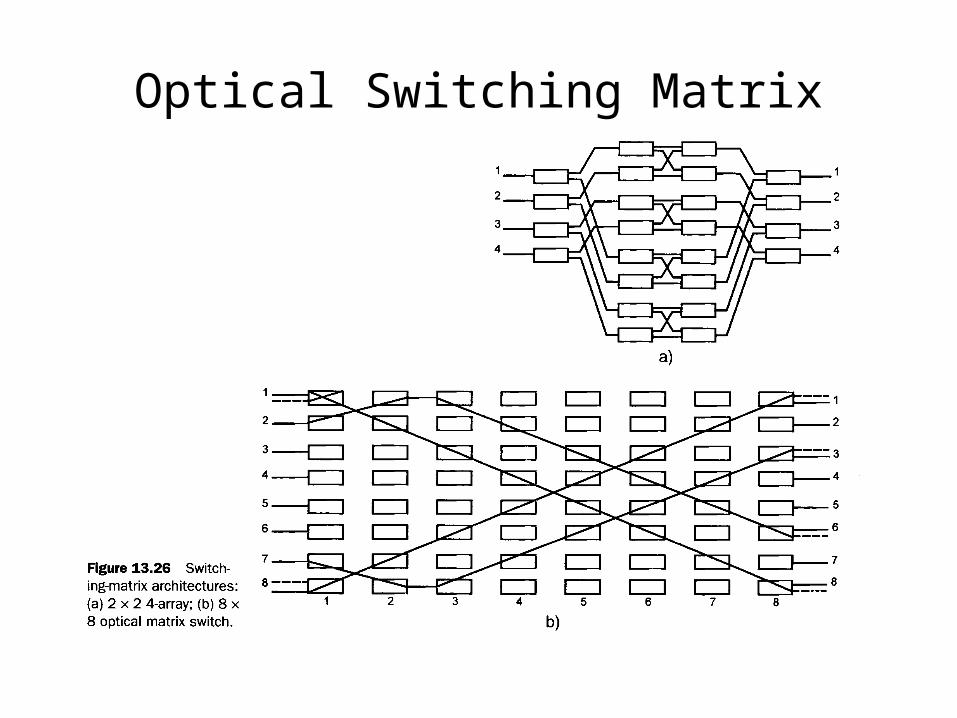
Optical Switching Matrix

Switching methods
• Thermo-optic
• Tunable filters
• Liquid crystal
• Electro-optic
• Liquid reflection
• MEMS

Tunable Optical Filters

Agilent Bubble Switch
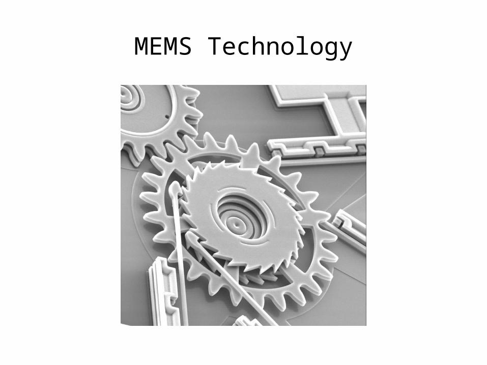
MEMS Technology

Wavelength Converters
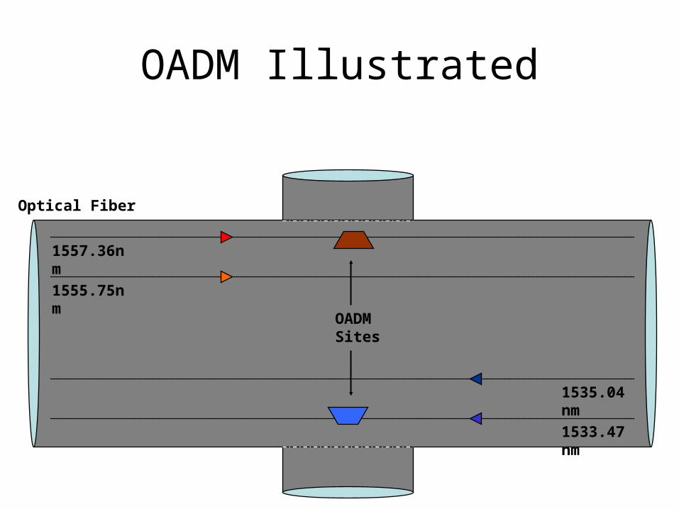
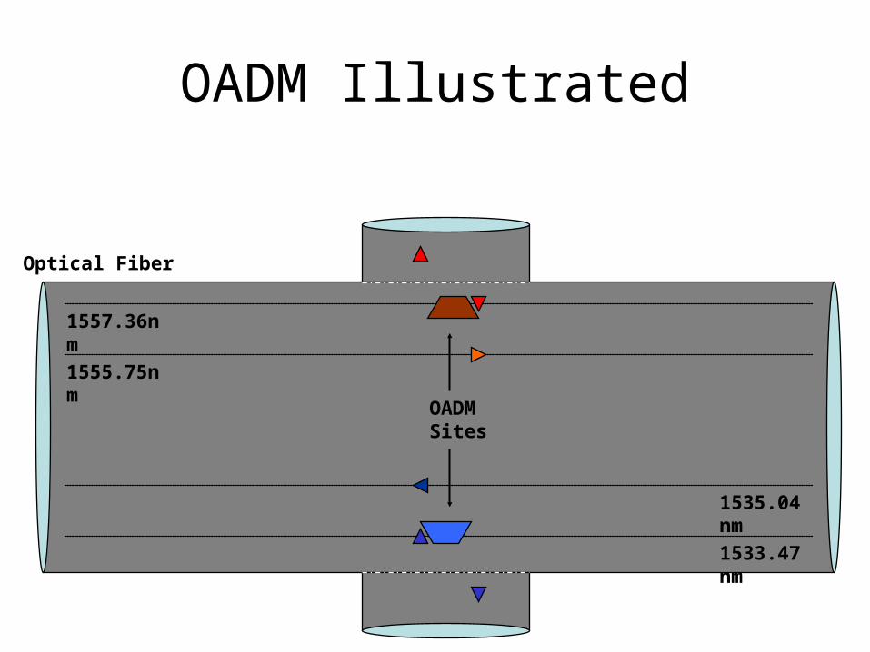
OADM Illustrated
OADM Sites
1557.36nm
1555.75nm
1533.47nm
1535.04nm
Optical Fiber

OADM Illustrated
OADM Sites
1557.36nm
1555.75nm
1533.47nm
1535.04nm
Optical Fiber

OADM Illustrated
OADM Sites
1557.36nm
1555.75nm
1533.47nm
1535.04nm
Optical Fiber
OADM Illustrated
OADM Sites
1557.36nm
1555.75nm
1533.47nm
1535.04nm
Optical Fiber

OADM Illustrated
OADM Sites
1557.36nm
1555.75nm
1533.47nm
1535.04nm
Optical Fiber

OADM Illustrated
OADM Sites
1557.36nm
1555.75nm
1533.47nm
1535.04nm
Optical Fiber

Opaque vs. Transparent OXCs
• Opaque: every wavelength undergoes OEO conversion. S/N degradation does not accumulate, simple route choice, can change wavelengths at each hop, simple network management
• Transparent: all-optical. Less expensive, dissipates less power, fewer interfaces, no electronics limit on bit rate. Works better in ring networks

MEMS OXC in Action (MEMX Co.)

Spectral Efficiency of WDM Systems
For =100 GHz and B=10 Gb/s, =10%
For =50 GHz and B=40 Gb/s, =80%
B

Transport Fiber
SONET Add/Drop Mux
Digital Crossconnect
WDMTransportEquipment
Add/Drop Channels
• Composed of WDM Transport EquipmentSONET ADD/Drop MuxesDigital Crossconnect
• AdvantagesOff the shelf technologyFull SONET Management and QOSFlexible routing at STS-1 or below
• DisadvantagesLargeExpensiveDiversity of management systemsDifficult ProvisioningExpensive interconnect cabling
Typical Network Structure

Types of WDM Networks
• Local area (LAN)
• Metropolitan area (MAN)
• Wide area (WAN)

Configurations of WDM Networks
• star—good for LANs
• bus (chain)--LANs
• ring—good for MANs and WANs
• hub—good for WANs; collection of stars or rings

Limitations on Performance, N
• Wavelength stability of diode lasers
• Nonlinear optical effects
• Crosstalk in the demultiplexing process

OC-48 Link Performance vs. Distance
0 km
16 km
25 km
41 km
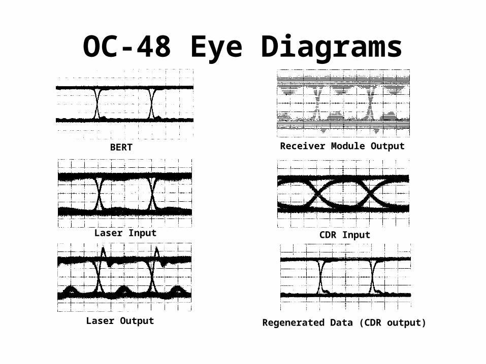
OC-48 Eye Diagrams
BERT
Laser Input
Laser Output
Receiver Module Output
Regenerated Data (CDR output)
CDR Input

10Gb/s Eye vs. Transmission DistanceOptical Signal Input to CDROptical Signal Input to CDR
0 km
12 km
16 km
25 km
37 km
41 km

OC-192 Link TestingEye Diagrams throughout the system
Input Signal from BERT
After Laser Driver
Optical Signal from Laser
After Receiver Module
Input to CDR
Regenerated Data

•Reduced Cost•More Compact•Lower Power•Rapid physical layer protection switching
Simplified Operation, Administration,Management and Provisioning
•Simpler Network interface•Fewer different management systems•Leverages traditional link based management and protection
Advantages
Disadvantages• No low level traffic grooming• Not directly compatible with SONET protection protocols• Less bandwidth efficient• No “statistical multiplexing” oflow level STS-n data streams
The Future?

Design Objective120 Gb/s Optical WDM Cross Connect Switch
Cross Connect Configuration• 3x3 fiber switch• 4 channels/fiber• 10 Gb/s/channel
Electronic Switch Core• OC192/OC48 compatible
Optical MUX/DEMUX• ITU WDM channels
Key Technology• Rockwell GaAs HBT• Ortel DFB Laser/PIN
WDM with Electronic Switching Technology
• Data regeneration/retiming• Wavelength translation• Low crosstalk• OC192/OC48 compatible
• Realizable with current state-of-the-art production technology
• Potential for additional processing of input signal (smart switch)
Advantages of an Electronic Core

WEST System DemonstrationConfiguration Overview
ST
S-4
8 A
dd
ST
S-4
8 D
rop
ST
S-4
8 D
rop
ST
S-4
8 A
dd
Dem
ux
Mu
x
Spl
itte
r
2.5
Gb
/sE
rror
De
t.
2.5
Gb
/sE
rror
De
t.
2.5
Gb
/sP
at. G
en
2.5
Gb
/sP
at. G
en
STS-192 Add
STS-192 Add
ST
S-4
8 A
dd
ST
S-4
8 D
rop
STS-192/STS-48 Drop
STS-192 Drop
ST
S-4
8 D
rop
ST
S-4
8 A
dd
Dem
ux
Mu
x
Spl
itte
r
MuxDemux
Splitter
WDMMonitor With GPIB
Optical Spectrum Analyzer
2.5
Gb
/s
Err
or D
et.
2.5
Gb
/s
Err
or D
et.
2.5
Gb
/s
Pat
. Gen
2.5
Gb
/s
Pat
. Gen
10 Gb/s Pat. Gen
10 Gb/s Pat. Gen
10 Gb/s Error Det.
Scope
µ-wave SpectrumAnalyzer
Scope
ScopeSplitterInternal Nodes
Electrical Power Splitter
WEST Crossconnect
Long Reach Fiber
Short Reach Fiber
•Configured as an Add/Drop node
•4 Channels of Add/Drop
•8 Transmission Channels
•Optical Monitoring
•Eye diagram monitoring
•Clock monitoring for acquisitiondemonstration

Switch Module Features:• 120 Gb/s data throughput• Twelve 10 Gb/s channels• VXI Management and Control
High Speed Package Features:• Clean high speed interface• High Isolation• Thermal management
Switch Chip Highlights:•Suitable for larger switching fabrics•GaAs/AlGaAs HBT•Low crosstalk & jitter generation•Die size: 4.8 x 5.1 mm2
•4600 transistors•Pdiss: 7.4 W
10Gb/s
12x12 VXI Switch ModuleFeature Highlights

WDM Network Design Considerations
• transparent or opaque?
• power level? (high better for receivers, low better for transmitters and NLO)
• branching configuration?
• channel spacing? (small better for capacity, large better for crosstalk)