EE 221 Circuits II - Department of Electrical and Computer ...eebag/Chap 13 Mutually Coupled...
26
EE 221 EE 221 Circuits II Circuits II Chapter 13 Magnetically Coupled Circuits 1
Transcript of EE 221 Circuits II - Department of Electrical and Computer ...eebag/Chap 13 Mutually Coupled...

EE 221EE 221Circuits IICircuits IIChapter 13Magnetically Coupled Circuits
1

Magnetically Coupled CircuitsMagnetically Coupled Circuits
13.1 What is a transformer?13.2 Mutual Inductance13.3 Energy in a Coupled Circuit 13.4 Linear Transformers13.5 Ideal Transformers13.6 Applications
2

13.1 What is a transformer? 13.1 What is a transformer?
It is an electrical device designed on the basis of the concept of magnetic couplingIt uses magnetically coupled coils to transfer energy from one circuit to anotherIt is the key circuit element for stepping up or stepping down ac voltages and currents, impedance matching, isolation, etc….
3

13.2 Mutual Inductance 13.2 Mutual Inductance It is the ability of one inductor to induce a voltage across a neighboring inductor, Mutual inductance is measured in henrys (H).
4
dtdiMv 1
212 = dtdiMv 2
121 =
V2: Open-circuit voltage across coil 2
V1: Open-circuit voltage across coil 1
dtdiLv 1
11 = dtdiLv 2
22 =

13.2 Mutual Inductance 13.2 Mutual Inductance If a current enters the dotted terminal of the first coil, the reference polarity of the voltage in the second coil is positive at the dotted terminal.
5Illustration of the dot convention.

13.2 Mutual Inductance 13.2 Mutual Inductance
)connection aiding-(series 221 MLLL ++=
)connection opposing-(series 221 MLLL −+=
6
Series connection of two mutually coupled inductors; (a) series-aiding connection, (b) series-opposing connection.

Problem 1:Problem 1:
7

13.2 Mutual Inductance 13.2 Mutual Inductance
8
Time-domain analysis of a circuit containing coupled coils.
Frequency-domain analysis of a circuit containing coupled coils

13.2 Mutual Inductance 13.2 Mutual Inductance
Example 1
Calculate the phasor currents I1 and I2 in the circuit shown below.
A04.1491.2I A;39.4901.13I 21 °∠=°−∠=
9
Ans:

13.3 Energy in a Coupled Circuit (1)13.3 Energy in a Coupled Circuit (1)The coupling coefficient, k, is a measure of the magnetic coupling between two coils; 0≤k≤1.
21LLMk =
10
• The instantaneous energy stored in the circuit is given by
• (+) if both currents enter or leave the dotted sides• (-) if one current enters the dotted side and the other
current leaves dotted side.
21222
211 2
121 iMiiLiLw ±+=

13.3 Energy in a Coupled Circuit 13.3 Energy in a Coupled Circuit
Example 2Consider the circuit below. Determine the coupling coefficient. Calculate the energy stored in the coupled inductors at time t = 1s if v=60cos(4t +30°) V.
11
Ans: k=0.56; w(1)=20.73J

Problem 20:Problem 20:
12

13.4 Linear Transformer 13.4 Linear Transformer
13
Let V1 and V2 be the voltages across the transformer terminals:
−
+
1V−
+
2V
reflected
L
ZLjZLj
MLjZIV
ZRZwhereMIjILjZ
MIjILjV
+=+
+==⇒
+==−+
−=
122
2
111
1
22
1222
2111
)()(
0)(
ωωωω
ωωωω

13.4 Linear Transformer 13.4 Linear Transformer
A1.1135.0I ;1.5314.100Z 1in °∠=Ω°−∠=
14
Example 3In the circuit below, calculate the input impedance and current I1. Take Z1=60-j100Ω, Z2=30+j40Ω, and ZL=80+j60Ω.
Ans:
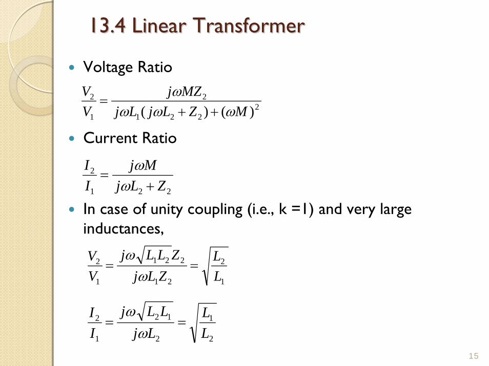
13.4 Linear Transformer 13.4 Linear Transformer
15
Voltage Ratio
Current Ratio
In case of unity coupling (i.e., k =1) and very large inductances,
2221
2
1
2
)()( MZLjLjMZj
VV
ωωωω
++=
221
2
ZLjMj
II
+=
ωω
1
2
21
221
1
2
LL
ZLjZLLj
VV
==ω
ω
2
1
2
12
1
2
LL
LjLLj
II
==ω
ω

13.4 Linear and Ideal Transformer 13.4 Linear and Ideal Transformer
16
The inductance L is proportional to the number of turns squared.
In case of an ideal Transformer,
nNN
aNaN
LL
ZLjZLLj
VV
=====1
22
1
22
1
2
21
221
1
2
ωω
nNN
LL
LjLLj
II 1
2
1
2
1
2
12
1
2 ====ω
ω
L=10-3N2r2/(228r+254l)

13.5 Ideal Transformer 13.5 Ideal Transformer
nNNn
NN 1
II
VV
2
1
1
2
1
2
1
2 ====
17
An ideal transformer is a unity-coupled, lossless transformer in which the primary and secondary coils have infinite self-inductances.
(a) Ideal Transformer(b) Circuit symbol
V2>V1 → step-up transformerV2<V1 → step-down transformer

13.5 Ideal Transformer 13.5 Ideal Transformer
Example 4
An ideal transformer is rated at 2400/120V, 9.6 kVA, and has 50 turns on the secondary side.
Calculate: (a) the turns ratio, (b) the number of turns on the primary side, and (c) the current ratings for the primary and secondary windings.
18
Ans:(a) This is a step-down transformer, n=0.05(b) N1 = 1000 turns(c) I1 = 4A and I2 = 80A

Problem 36Problem 36
19

13.6 Applications13.6 Applications
Transformer as an isolation device to isolate ac supply from a rectifier
20
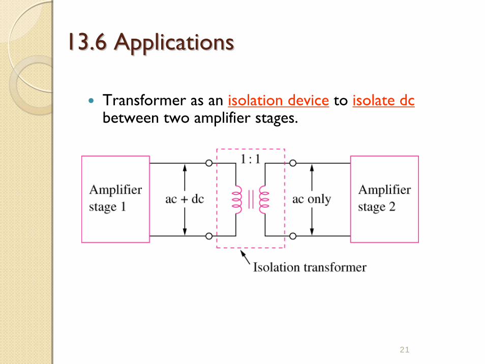
13.6 Applications 13.6 Applications
Transformer as an isolation device to isolate dcbetween two amplifier stages.
21

13.6 Applications 13.6 Applications
22
Transformer as a matching device
Using an ideal transformer to match the speaker to the amplifier
Equivalent circuit

13.6 Applications 13.6 Applications
Example 5
Calculate the turns ratio of an ideal transformer required to match a 100Ω load to a source with internal impedance of 2.5kΩ. Find the load voltage when the source voltage is 30V.
23
Ans: n = 0.2; VL = 3V

13.6 Practical Electric Utility transformers13.6 Practical Electric Utility transformers
24
• Used to step-up or step-down the voltage

Ideal Auto-TransformerAuto-transformers are used in cases where the voltage ratio is less than 2.Note that there is only one winding, the primary and secondary side share part of this winding.There is no electrical isolation between the primary and secondary sides.The apparent power rating of an auto-transformer is often much higher than a two-winding transformer of the same size (see example 13.10)

3-Phase Transformer