Edwin I. Hatch, Unit 1, HNP-ISI-ALT-14, Version 1 ... fileMark J. Ajluni, P.E. Southern Nuclear ....
43
Mark J. Ajluni, P.E. Southern Nuclear Nuclear Li censing Di r ector Operating Company, Inc. 40 I nverness Ce n ter Parkway Post OHice Bo x 1 295 B irmingham. Alabam a 35 201 T el 205.992.7673 Fax 205 . 992.7885 October 24, 2011 SOUTHERN '\ COMPANY Docket Nos .: 50-321 NL-11-2155 U. S. Nuclear Regulatory Commission ATTN: Document Control Desk Washington, D. C. 20555-0001 Edwin I. Hatch Nuclear Plant - Unit 1 HNP-ISI-ALT-14, Version 1 Temporary Non-Code Repair of Plant Service Water Piping Ladies and Gentlemen: Pursuant to 10 CFR 50.55a(a)(3)(ii), Southern Nuclear Operating Company (SNC) hereby requests Nuclear Regulatory Commission (NRC) approval of the enclosed Alternative HNP-ISI-ALT-14, Version 1, which proposes a temporary non-code repair to leaks discovered in the Hatch Nuclear Plant Unit 1 (HNP-1) Plant Service Water (PSW) System. During inspection of HNP-1 buried demineralized water transfer piping adjacent to the HNP-1 Reactor Building to address tritium leakage, two leaks were identified in a nearby run of PSW piping exposed by the excavation. An operability determination concluded that PSW system operability is maintained. However, that determination is based in part on river temperature (the PSW source) remaining above 46°F. As discussed in the enclosure, the proposed non-code repair meets most of the requirements for a "full code repair"; however, to perform a repair/replacement activity, IWA-4412 of the 2001 Edition of the ASME Section XI Code with Addenda through 2003, requires that "defect removal be accomplished in accordance with the requirements of IWA-4420 ." Removing the defects would require that the system be taken out of service, necessitating a plant shutdown. In order to preclude a shutdown, SNC proposes to leave the defects in service and perform a temporary non-code repair requiring NRC approval. SNC requests NRC approval of HNP-ISI-ALT-14, Version 1, by Thursday, October 27, 2011 to support repairs scheduled to begin Friday, October 28 , 2011 . The SNC need date is based on the plant's ability to begin the repair and on the fact that the minimum temperature for repair based on welding preheat requirements is 60°F, while the current river temperature is 64°F and trending down . In addition, considering the structural limit of 46°F established by the operability determination, historical seasonal river temperature trends and allowing for a 30 day mission time, the repair should be completed by November 9, 2011 . If approved, the non-code repair would remain in place until the next refueling outage (scheduled for February 2012) or until the next cold shutdown of
Transcript of Edwin I. Hatch, Unit 1, HNP-ISI-ALT-14, Version 1 ... fileMark J. Ajluni, P.E. Southern Nuclear ....

Mark J. Ajluni, P.E. Southern Nuclear Nuclear Li censing Di rector Operating Company, Inc.
40 Inverness Center Parkway Post OHice Box 1295 Birmingham. Alabama 35201
Tel 205.992.7673 Fax 205.992.7885
October 24, 2011 SOUTHERN '\ COMPANY
Docket Nos.: 50-321 NL-11-2155
U. S. Nuclear Regulatory Commission ATTN: Document Control Desk Washington, D. C. 20555-0001
Edwin I. Hatch Nuclear Plant - Unit 1 HNP-ISI-ALT-14, Version 1
Temporary Non-Code Repair of Plant Service Water Piping
Ladies and Gentlemen:
Pursuant to 10 CFR 50.55a(a)(3)(ii) , Southern Nuclear Operating Company (SNC) hereby requests Nuclear Regulatory Commission (NRC) approval of the enclosed Alternative HNP-ISI-ALT-14, Version 1, which proposes a temporary non-code repair to leaks discovered in the Hatch Nuclear Plant Unit 1 (HNP-1) Plant Service Water (PSW) System. During inspection of HNP-1 buried demineralized water transfer piping adjacent to the HNP-1 Reactor Building to address tritium leakage, two leaks were identified in a nearby run of PSW piping exposed by the excavation. An operability determination concluded that PSW system operability is maintained. However, that determination is based in part on river temperature (the PSW source) remaining above 46°F.
As discussed in the enclosure, the proposed non-code repair meets most of the requirements for a "full code repair" ; however, to perform a repair/replacement activity, IWA-4412 of the 2001 Edition of the ASME Section XI Code with Addenda through 2003, requires that "defect removal be accomplished in accordance with the requirements of IWA-4420." Removing the defects would require that the system be taken out of service, necessitating a plant shutdown. In order to preclude a shutdown, SNC proposes to leave the defects in service and perform a temporary non-code repair requiring NRC approval.
SNC requests NRC approval of HNP-ISI-ALT-14, Version 1, by Thursday, October 27, 2011 to support repairs scheduled to begin Friday, October 28 , 2011 . The SNC need date is based on the plant's ability to begin the repair and on the fact that the minimum temperature for repair based on welding preheat requirements is 60°F, while the current river temperature is 64°F and trending down. In addition, considering the structural limit of 46°F established by the operability determination, historical seasonal river temperature trends and allowing for a 30 day mission time, the repair should be completed by November 9, 2011 . If approved, the non-code repair would remain in place until the next refueling outage (scheduled for February 2012) or until the next cold shutdown of

U. S. Nuclear Regulatory Commission NL-11-2155 Page 2
sufficient duration to perform the repair/replacement activity, whichever comes first. A similar temporary non-code repair was approved for HNP previously (reference NRC SER dated January 14, 2011 for HNP-ISI-AL T-1 0).
The excavations where the leaks in the PSW piping were observed are located in the Protected Area of the plant adjacent to the Unit 1 Reactor Building, and are surrounded by concrete or steel structures on 75% of the access pathway. The Protected Area is a heavily controlled, low-traffic environment, and metal barriers placed to increase awareness of the excavation site will also prevent smaller vehicles (such as golf carts) from reaching the excavation. In addition, the excavation site is covered by grating material evaluated to meet missile protection criteria for the exposed pipe.
The details of the proposed alternative are contained in Enclosure 1 to this letter. Documentation of Engineering Judgment (DOEJ)-HRSNC341 070-S001 performed by SNC is provided as Enclosure 2 and addresses the PSW piping leaks with respect to ASME Section XI Code Case N-513-3. Enclosure 3 provides DOEJ-HRSNC341 070-M001 , also performed by SNC, which addresses the potential for PSW flow diversion due to the observed pipe degradation.
This letter contains no NRC commitments. If you have any questions, please contact B. D. McKinney at (205) 992-5982.
Respectfully submitted,
M. J. Ajluni Nuclear Licensing Director
MJAlDWD
Enclosures: 1. Alternative HNP-ISI-ALT-14, Version 1.0, Temporary Non-Code Repair of Plant Service Water Piping
2. Documentation of Engineering Judgment (DOEJ)HRSNC341 070-S001, Evaluation of Plant Service Water Pipe Leaks per ASME Code Case N-513-3
3. Documentation of Engineering Judgment (DOEJ)HRSNC341 070-M001, Evaluation of Unit 1 Plant Service Water (PSW) Flow with Pipe Degradation

U. S. Nuclear Regulatory Commission NL-11-2155 Page 3
cc: Southern Nuclear Operating Company Mr. S. E. Kuczynski, Chairman, President & CEO Mr. D. G. Bost, Chief Nuclear Officer Mr. D. R. Madison, Vice President - Hatch Ms. P. M. Marino, Vice President - Engineering RTYPE: CHA02.004
U. S. Nuclear Regulatory Commission Mr. V. M. McCree, Regional Administrator Mr. W.C. Gleaves, NRR Senior Project Manager - Hatch Mr. E. D. Morris, Senior Resident Inspector - Hatch

Edwin I. Hatch Nuclear Plant - Unit 1 HNP-ISI-ALT-14, Version 1
Temporary Non-Code Repair of Plant Service Water Piping
Enclosure 1
Alternative HNP-ISI-ALT-14, Version 1.0 Temporary Non-Code Repair of Plant Service Water Piping

Enclosure 1 Hatch Nuclear Plant - Unit 1 Alternative HNP-ISI-AL T-14, Version 1.0 Temporary Non-Code Repair of Plant Service Water Piping
UNIT:
COMPONENT:
SYSTEM:
ASME CODE CLASS:
FUNCTION:
CODE REQUIREMENT:
Hatch Unit 1 This unit is in the fourth lSI interval which ends on December 31,2015.
10-inch !\Iominal Pipe Size (NPS) carbon steel piping with a nominal wall thickness of 0.365-inch.
Plant Service Water (PSW)
The PSW system was built to the requirements of ANSI B31.1, Power Piping Code. The portion of PSW containing this piping is treated as Class 3 for Section XI purposes.
This 10-inch diameter piping is the supply header for the Unit-1 , Division II, Reactor Building loads listed below:
• RHR and Core Spray Pump Room Coolers 1 T 41 B003A1B • RHR Pump Seal Coolers 1 E11 B002B/D • HPCI Pump Room Coolers 1T41 B005A1B • CRD Pump Room Coolers 1T41 B001A1B • Main Control Room HVAC Condensing Units 1Z41 B008B/C
Two leaks are located on the straight run of buried pipe adjacent to the Unit-1 Reactor Building and were identified by Maintenance personnel during the buried piping inspections. This piping was uncovered initially to address suspected leakage coming from Unit-1 buried piping. To perform a repair/replacement activity, IWA-4412 of the 2001 Edition of AS ME Section XI with Addenda through 2003 requires that "defect removal shall be accomplished in accordance with the requirements of IWA-4420." The defects will not be removed during PSW system operation because of the significant increase in the leak rate that would be incurred by removal of the degraded material. Therefore, a modification is proposed which is considered a ''temporary non-code repair," necessitating this alternative. See the Proposed Temporary Non-Code Repair section of this alternative for more details.
E1-1

Enclosure 1 Hatch Nuclear Plant - Unit 1 Alternative HNP-ISI-AL T-14, Version 1.0 Temporary Non-Code Repair of Plant Service Water Piping
ALTERNATIVE REQUIREMENT:
POSITIVE FLAW DETECTION DURING PLANT OPERATION:
HARDSHIP OF REPAIR:
In lieu of performing an ASME Code-compliant repair, Southern Nuclear Operating Company (SNC) is implementing the alternative requirements of ASME Code Case N-S13-3, "Evaluation Criteria for Temporary Acceptance of Flaws in Moderate Energy Class 2 or 3 Piping." This Code Case will be implemented until the next refueling outage which is currently scheduled to begin in February 2012 or until the next cold shutdown of sufficient duration to perform the repair/replacement. Compliance with the specified requirements of the Section XI Code would result in hardship without a compensating increase in the level of quality and safety; therefore, approval of this alternative per 10 CFR SO.SSa(a)(3)(ii) should be granted.
On October 21, 2011, two through-wall leaks were discovered in the PSW system. The initial leakage is documented in Hatch Condition Report 364491.
HNP-1 Technical Specifications (TS) 3.7.2 requires that two PSW subsystems and one UHS (Ultimate Heat Sink) be operable. Performing an ASME Code repair at this location during power operation would require that Division" of PSW be taken out of service. With a division of PSW out-of-service, TS 3.7.2 Condition E requires that the PSW subsystem be restored to Operable status within 72 hours. While the Technical Specification provides 72 hours for repair, doing so would result in the loss of one train of emergency cooling components during the repair window. In addition, isolation and draining of a PSW loop during power operation is complex and would expend a significant portion of the 72 hours allowed. Shutting the plant down to perform a Code repair vs. using the proposed temporary non-code repair is considered by SNC to be a hardship.
E1-2

Enclosure 1 Hatch Nuclear Plant - Unit 1 Alternative HNP-ISI-AL T-14, Version 1.0 Temporary Non-Code Repair of Plant Service Water Piping
DEGRADATION MECHANISM:
FLAW SIZING:
EVALUATION APPROACH AND RESULTS:
The exact cause of the degradation has not been confirmed, as it is internal to the pipe. However, based on the degradation pattern, the cause is expected to be localized corrosion. Additional areas of this piping were examined and found to have no degradation. This data, along with the required broadness examinations of ASME Code Case N-513-3, provides assurance as to a lack of potential additional broadness issues.
Detailed ultrasonic (UT) measurements were obtained around the area of the two leaks to better understand the scope of the degradation (See Figures 1 and 2 for Locations 1 and 2, respectively). At the location of one of the leaks, Location 1, the pipe wall thickness was found to be less than 0.200-inch in a circular shape that is 1-118-inches in diameter. At the location of the other leak, Location 2, the pipe wall thickness was found to be less than 0.200-inch in an elliptical shape that is 2-1/4-inches on the major axis and 2-inches on the minor axis. The published minimum wall thickness for this piping is 0.1 ~O-inches. However, an acceptable reading could not be obtained on any piping with a thickness less than 0.200-inches. The rest of the piping in the examination grid was found to have a wall thickness greater than 0.200-inches. For details, see Documentation of Engineering Judgment (DOEJ)-HRSNC341 070-S001 as provided in Enclosure 2.
Because PSW is functioning in an operable but degraded condition, the following issues as identified below were addressed to ensure that no harm to plant safety or public health exists. Once the proposed temporary non-code repairs are made, any potential adverse effects due to leakage would be mitigated.
Flaw Evaluation: A flaw evaluation was conducted in accordance with Section 3.0 of Code Case N-513-3 to evaluate the leak. The Code Case N-513-3 flaw evaluation determined that structural integrity is being maintained.
Stress Analysis: The added weight of the two plates to be welded to the affected piping (See Proposed Temporary Non-Code Repair below) was reviewed, and did not impact the stress analysis calculations.
E1-3

Enclosure 1 Hatch Nuclear Plant - Unit 1 Alternative HNP-ISI-AL T-14, Version 1.0 Temporary Non-Code Repair of Plant Service Water Piping
Flow Diversion: An analysis was performed to estimate the leakage from the piping based on the area of the flaw size that was below the thinnest measurable wall thickness, or 0.200 inches. Although the current leakage area is smaller than the flawed area that is below 0.200 inches, the analysis conservatively assumed that the area of the leakage would be equal to the flawed area below 0.200 inches. Based on the ultrasonic thickness readings, Location 1 was assumed to be 1.125 inches in diameter and Location 2 was assumed to be elliptical with a 2.25 inch major axis and a 2 inch minor axis. Conservatively this was modeled by assuming two 2" x 3" holes which is modeled as a 2.45" diameter hole. The model was run for this case and additionally for the loss of inventory from a 3.97" diameter hole in Division II of the PSW system. The results were then evaluated against the design flows to safety-related components during a LOCA using the PROTO_FLO model (2007 benchmark update). The results of this evaluation showed that with a 3.97-inch diameter hole in the 10-inch line, that all safety-related components would receive adequate PSW flow during a LOCA. The details are described in DOEJ-HRSNC341070-M001 for details. Therefore, with the worst case leak due to loss of material from the existing location, the PSW system would still be capable of providing the required cooling to all components.
Water Temperature: The Hatch Prompt Determination of Operability (PDO) discussed that the SNC Corporate Piping Stress Engineer noted that the piping will remain structurally sound and meet the B31.1 Code requirements as long as the pipe temperature remains above 46°F. The reasonable assumption is that the pipe temperature is the same as the process piping. The process system, in this case, is PSW. The present temperature of the PSW piping is greater than 46°F. To determine a PSW temperature projection, a review of fourteen years of PSW temperature data was performed which revealed that the earliest date that PSW was 46°F was December 9th
. Based on the 30-day mission time for PSW piping, repairs must be completed by November 9, 2011.
Spraying: The leak locations were considered for impact on other components. There is no equipment in this area that could be affected by these leaks. This information provides a reasonable expectation that this condition would not affect ability of the PSW systems, or other components located in the area to perform as designed.
Flooding: With respect to the potential for flooding due to excessive leakage into this area, there is only piping and no equipment in the excavated pit. This provides reasonable assurance that the components in this area would be capable of performing the necessary design functions in the event of flooding. Therefore, the amount of leakage into the area will not affect the operability determination of the PSW system.
E1-4

Enclosure 1 Hatch Nuclear Plant - Unit 1 Alternative HNP-ISI-AL T-14, Version 1.0 Temporary Non-Code Repair of Plant Service Water Piping
AUGMENTED EXAMINATIONS:
Flaw Growth Rate: As stated previously, the cause of the degradation is believed to be from localized corrosion. If further degradation were to occur on this area of the piping, it would be minimal and gradual with respect to the time frame for the next opportunity for piping repair (next refueling outage or until the next cold shutdown of sufficient time to perform the repair/replacement) . This assumption is further justified by the fact that the piping with the degradation is original plant piping, and has been in service for approximately 36 years. There is reasonable assurance that the calculations and evaluations associated with the current degradation would remain valid until a Codecompliant repair/replacement is performed. The daily rounds and the ongoing ultrasonic examinations performed on a 30-day frequency will enable Hatch to verify that structural integrity is maintained.
Based on the above discussion, SNC has determined that the structural integrity of the PSW piping at this location is being maintained and will continue to be maintained until a Code-compliant repair/replacement is performed.
To determine the extent of condition, five sample points, as specified by Code Case N-513-3, will be examined using ultrasonic thickness techniques. If any of these examinations identify piping with thickness measurements below the required minimum wall thickness, the condition will be documented in a condition report and this operability determination will be re-evaluated. This will meet the guidance of Code Case N-513-3.
The five sample points will be at the following locations: • Point 1 - Scan 2 feet of piping downstream of valve 1 P41 F380A • Point 2 - Scan 2 feet of piping downstream of valve 1 P41 F380B • Point 3 - Scan the 8 feet area in excavation #1 as previously
directed by the Buried Pipe Program • Point 4 - Scan 2 feet of piping between valve 1 P41 F066 and the wall
penetration • Point 5 - Scan 2 feet of piping between valve 1 P41 F067 and the wall
penetration.
The UT thickness examinations for the five sample pOints identified above are expected to be completed prior to November 20, 2011 .
E1-5

Enclosure 1 Hatch Nuclear Plant - Unit 1 Alternative HNP-ISI-AL T-14, Version 1.0 Temporary Non-Code Repair of Plant Service Water Piping
PROPOSED TEMPORARY NON-CODE REPAIR: Several repair/replacement activities were evaluated and it is proposed that the
addition of two contoured plates to the affected sections of piping by means of welding be made to isolate the leaks (see Figure 4). This option allows the welding on the two attachments to be located in an area with minimal degradation, ensuring a structurally sound load path while minimizing the risk of "burn-through" and increased leakage. The design will also ensure that the configuration of the repair will allow continued wall thickness monitoring of the region by ultrasonic examination to ensure that future degradation will not adversely impact the structural capability of the repaired section.
The degraded piping is 10-inch, Schedule 40 (0.365-inch nominal wall), seamless carbon steel piping. The repair plates will be constructed from either plate or pipe; the Hatch site plans on using plate. In either case, the thickness of the repair plates will be 0.365-inch nominal wall from P-No.1 carbon steel material having an allowable stress of 15,000 psi up to 650°F. If it is determined that plate will not work, piping will be used.
Plate #1 covering Location #1
This location is essentially at the 12 o'clock position. The size of this plate was based on inputs from the ultrasonic thickness measurements taken as requested by the SNC Corporate Stress Group. The UT examiner was asked to find where the wall thickness measured at least 0.200-inches and at least 0.300-inches away from each leaking location in four directions. The examiner was able to get the requested eight ultrasonic measurements; a copy of the test report is enclosed as Figures 1 A & 1B. Based on these measurements (ref. Figure 2), a 3-inch by 3-inch plate will be positioned over Location #1 as shown in Figure 4.
Plate #2 covering Location #2
This location is at the 7 o'clock position looking south. The size of this plate was based on inputs from the ultrasonic thickness measurements taken as requested by the SNC Corporate Stress Group (ref. Figure 3). The UT examiner was asked to find where the wall thickness measured at least 0.200inches and at least 0.300-inches away from each leaking location in four directions. The examiner was able to get seven UT readings; however, a measurement was not able to be obtained for the ultrasonic point for the 0.200inch location at the "upper" side for Location #2 because of ID surface irregularities. The Hatch site design engineering group evaluated the NDE results and designed the 3-inch by 6-inch plate as shown in Figure 4.
E1-6

Enclosure 1 Hatch Nuclear Plant - Unit 1 Alternative HNP-ISI-ALT-14, Version 1.0 Temporary Non-Code Repair of Plant Service Water Piping
Additional details from Figure 4 are provided in the enclosed Sketch 1, which includes dimensions between the edges of Plate # to the 0.300-inch dimension.
As noted above, ID surface irregularities limited the UT thickness measurements. Although this cannot be confirmed, SNC is of the opinion that a better representation of the thickness at Location #2 is depicted in the enclosed Sketch 2.
All welders and welding procedure specifications shall be qualified for groove welding in accordance with the ASME Section XI Code. The new pressure boundary will now be located at the reinforcing plate attaching weld. The welding process to be used for attaching the reinforcing plate will be the shielded metal arc welding (SMAW) process. If rejectable indications are identified during performance of nondestructive examination, the indications will be removed and the attachment weld repaired in accordance with applicable provisions of ASNIE Section XI and ANSI 831.1.
The welding is to be performed with water in the line and with the system pressurized to approximately 120 psig. SNC believes that this will not create any problems based on the following factors:
• Welding with water in a pipe is performed frequently in the industry and, as discussed above, the water temperature meets the 60°F minimum preheat.
• The measurements noted in Figures 2 and 3 indicate that the welding will be performed on thicknesses ranging from 0.200-inch to 0.300-inch thick.
• With the water in the system acting as a heat sink, the resulting heat affected zone of the piping base material caused by the welding should be relatively shallow.
• Since only the inner 0.200-inch of the base material is required for pressure containment, welding on O.200-inch thick to O.300-inch thick base material would not be expected to encroach upon the Coderequired minimum wall thickness and should have no impact on the load bearing capability of the piping during the welding process.
The completed welds will be VT examined per ANSI 831.1 and any indications evaluated per the requirements of ANSI 831.1. A pressure test will then be performed as required by IWA-4540 of the Section XI Code. The pressure test with be accompanied by a visual VT-2 examination.
Additionally, a liquid penetrant examination will be performed in accordance SNC procedure NNiP-ES-024-301. The examination will be performed no less
E1-7

Enclosure 1 Hatch Nuclear Plant - Unit 1 Alternative HNP-ISI-AL T-14, Version 1.0 Temporary Non-Code Repair of Plant Service Water Piping
CODE CASE N-513-3 ACTION PLAN:
than 48 hours after completion of the weld to ensure no delayed cracking occurs. (This examination is consistent with the requirements for weld overlay repair examinations made on P-No. 1 material using ASME Code Case N-6611, which has been accepted for use in Regulatory Guide 1.147). NMP-ES-024301 provides techniques and acceptance criteria to be used for the performance of Liquid Penetrant Examinations at the Hatch, Farley, and Vogtle nuclear plants. Indications will be evaluated per the following procedural acceptance criteria:
1. Relevant indications are indications which result from imperfections. Only indications with major dimensions greater than 1 /16-inch shall be considered relevant imperfections.
2. Imperfections producing the following indications are unacceptable:
Any cracks or linear indications.
Rounded indications with dimensions greater than 3/16-inch.
Four or more rounded indications in a line separated by 1 /16-inch or less edgeto-edge.
Ten or more rounded indications in any six square inch area with the major dimension of this area not to exceed six inches with the dimension taken in the most unfavorable location relative to the indications being evaluated.
3. An operating system VT -2 pressure test will then be performed as required by IWA-4540 of the Section XI Code.
The following actions will be performed by SNC for this component until the proposed temporary non-code repair is performed:
• Site personnel will perform daily rounds to identify further degradation of the affected area as evidenced by a significant increase in the leakage rate. If a significant increase in leakage is detected an ultrasonic examination will be performed to assure that the criteria used to evaluate the structural integrity remains valid.
• The area will be ultrasonically examined on a 30 day frequency to assure that unexpected degradation is not occurring and that the structural integrity of the piping is being maintained.
E1-8

Enclosure 1 Hatch Nuclear Plant - Unit 1 Alternative HNP-ISI-AL T-14, Version 1.0 Temporary Non-Code Repair of Plant Service Water Piping
STATUS:
ALTERNATIVE DURATION
• The PSW temperature will be monitored to ensure that it remains above 46°F.
The following actions will be subsequently performed by SNC in the time period after the temporary non-code repair is made until the ASME Section XI repair/replacement is performed:
• An ASME Section XI repair/replacement will be performed before the completion of the Hatch Unit 1 1 R25 refueling outage currently scheduled to begin in February 2012 or during the next cold shutdown judged to be of sufficient time to perform the repair/replacement, whichever occurs first.
• Site personnel will perform daily rounds to identify any signs that additional degradation is occurring.
• The area around the temporary repair will be ultrasonically examined on a 3~-day frequency to assure that degradation outside of the repaired area is not occurring and that the structural integrity of the piping is being maintained.
This alternative is awaiting NRC approval.
This alternative will remain in effect until an ASME Section XI Code repair/replacement is performed during the Hatch Unit-1 1 R25 refueling outage or until the next cold shutdown of sufficient duration to perform the repair/replacement, whichever occurs first.
E1-9

---
Enclosure 1 Hatch Nuclear Plant - Unit 1 Alternative HNP-ISI-ALT-14, Version 1.0 Temporary Non-Code Repair of Plant Service Water Piping
Southern Nuclear Operating Company
Nuc'ur 1SOUIMMA Management 1
"-"~ .natrucUon II
Description of .tem Enmfned:
S c.e c~.. J... M.terial Typ&:
8.CJS [J SIS Other. c.llbratlon Standard Seri•• Number:
Sound Path Screen Dt$tance:
I , I!;) ,,,S<:..lt·~~VI Ro.."" ~ SmaflMt S¢1Wf"I DtvtaJon:
Ultr8SOf'lic Thickness Examination ProceduJe
Date: / --2/- 1 /
Trerwdueer Manuf«lCturer:K &4 Seria. Number
C
EXAM'NATIOIi RESULTS
Exam.n r:
l.eveJ, \
NMP·ES.024~S t 1 Version 3.0
PE!fle 15 of 17
FrequenCy: ~,o
MHz
MeteNd I OJ ••
ConJinuoUl
Figure 1A - Ultrasonic Thickness Test Report - Page 1 of 2
E1-10
Enclosure 1 Hatch Nuclear Plant - Unit 1 Alternative HNP-ISI-ALT-14, Version 1.0 Temporary Non-Code Repair of Plant Service Water Piping
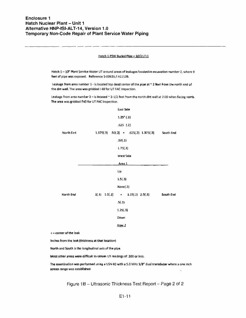
"ate)) 1. psw Iluded Pig!! -1.0/21111
Hatch 1- 10" PI';) Service Water UT around re $ of rel ka,ges. IQca~ in excavatiOrl number 2, wl\ere 9 ~et of pipe WiJHXJ)O d. Reference S..()()631/ Hi 139.
Leakage from area numb r 1- is- located top dead centerof the pip@ at N :2 feet from the 110Ft end of the dirt wall. The a rl!it was gridded I 48 for UT ~AC rn etlon.
leaka~ from ar a number 2 -Is [o~.ated ~ 2-1/2 feet from the north d irt waft at 7:00 when r: clng north. The area was 8rr~ded F40 for lJT FAC Inspect on.
East Side
1.25" (.3)
.625 (.2)
Nortn End 1.375(.3) .50(.2) ., 625(.2) 1.375(.3) s.:.u End
.SOP)
1.75(.3)
West Slde
Areal
Up
1.5(.3)
Nonel.2.)
North End 3(.3) 1.0( .2) + 1.25(.2) 2.s( ) South EM
.5f.2 ~
1.2s.{.3}
.. ". center of the leak
Inelles ' fom the lea~ (thickness at that locallon l
North and South is the 1o~lludlnal $ of the pipe.
Mo~totfler irea~ were d fflcult to obtain UT readings 0 .100 or less.
The examIn I[on WilS performed using a USN 60 wi h a 5.0 MHz 3/8" dual transdlJC.'@rwhlr. a OM Inch screen fa was fStabllsl1~ .
Figure 18- Ultrasonic Thickness Test Report - Page 2 of 2
E1-11

Enclosure 1 Hatch Nuclear Plant - Unit 1 Alternative HNP-ISI-AL T-14, Version 1.0 Temporary Non-Code Repair of Plant Service Water Piping
Location 1
East
1.25{.3)
O.625{.2)
North 1.375(.3} O.50{.2) X 0.625(.2) 1.375(.3) South
0.50(.2)
1.75(.3)
West
Note: 1) X- Location ofthe Indication
2) The numbers represent the distance of the ultrasonic thickness measurement from the leak and the numbers in parentheses are the thicknesses of the base material. All measurements are in inches.
Figure 2 - Leak Location 1
E1-12

Enclosure 1 Hatch Nuclear Plant - Unit 1 Alternative HNP-ISI-ALT-14, Version 1.0 Temporary Non-Code Repair of Plant Service Water Piping
Location 2
Up
-U5~.3) i
None(.2) I
North 3.0(.3) 1.0(.2) I X 1.2~(.2) 2.5(.3) South
0.5(.2)
1.25(.3)
Down
Note: 1) X- Location ofthe Indication 2) The numbers represent the distance ofthe ultrasonic thickness
measurement from the leak and the numbers in parentheses are the thicknesses of the base material. All measurements are in inches.
Figure 3 - Leak Location 2
E1-13

Enclosure 1 Edwin I. Hatch - Unit 1 Alternative HNP-ISI-ALT-14, Version 1.0 Temporary Non-Code Repair of Plant Service Water Piping
!'CIr[s. I. r .... -ol o~ r'ol-O;? to r ...... co,...plr''',"~ly ..... CIo.I1c;I plfl1.4 2. /ioU d_t\Tior.s '" Ind"!_ '3. Ii' I'100I. to t;.. ~~c:i ond Ul.pp,.d to. Q.cc .p\ ~. "'1 <l L~() tlo." Of ,.' 1'101.4' ....:)y "'* oQ,d)IXt~ :.)6' ..... r:otn '3io-ec.ti()rl~
~ r+~~ 1" fI;:r~~O~: ~.~: ~'t4~pI::=~,'~:;~ ..::;()(' oc l't!f'"o bi t> 7. It..,... <\ 1CF>ij ~~ to Iw Oo"",,"Uai olong oft 0( ptr:>
T"'~~ /r"",:""~l!,;,.l~g"''' """. I~-' "'I r"'"... :~:,.'I,l 11...1..1.. TMrD:~
.. ~nlc~\l1ol.t..1~=~ :~'<':~'.' rT-,-~ [Jf rOUilj. TD O~')1.;1 ~ I I....
1"1 .. -r (_tI" I
~. ,. pu~cr~)c-'~--- --'1.,.'-----1 (L ook"'~ ~th>
,• ftoII.~/'lilAl. .......1.. TI4I CI;).I(SS
'I'J ~'141tl.,jQ[)")
I rl'''"'!)(c,Ji'oIIDCO ....~L l~ltxf.£SS' n'c;o;s TII.... eli: (OU"'-- TO o...i'Or ) 'So
I .•. """. ·Ll
i:.i- ,-,\-- 1---~--- p~'(' PLAC(S>~... --"""~ ~.'-" Tt~ <\
IIE"I ,
Figure 4 - Proposed Non-Code Repair
E1-14

Enclosure 1 Hatch Nuclear Plant - Unit 1 Alternative HNP-ISI-ALT-14, Version 1.0 Temporary Non-Code Repair of Plant Service Water Piping
HAACiIrw.. VALL THlCKNESS' ~ t~ ~
IllEGRA II£D VAlL TI{ICt().f[SS <1.ts.S TiW4 DR EQUAL TO o.2ilO")
Sketch 1 from Figure 4 - Measured Details for Plate #2
THIO(NESS
~.
1-----* ----1
Sketch 2 from Figure 4 - Best Estimate Details for Plate #2
E1-15

Edwin I. Hatch Nuclear Plant - Unit 1 HNP-ISI-ALT-14, Version 1
Temporary Non-Code Repair of Plant Service Water Piping
Enclosure 2
Documentation of Engineering Judgment (DOEJ)-HRSNC341 070-S001, Evaluation of
Plant Service Water Pipe Leaks per ASME Code Case N-S13-3

Southern Nuclear Operating Company
DOCUMENTATION OF ENGINEERING JUDGMENT
DOEJ-HRSNC341070-S001
Evaluation of Plant Service Water Pipe Leaks per ASME Code Case N-513-2 and N-513-3
Version Record Version Originator/Date Rev iewer/Date
No. Signature Signature
1 An Nguyen I October 22, 201 1 Y. Jani I October 22, 2011
2 An Nguyen I October 24, 2011rx1~ Y. Jani I October 24, 2011 _r1r_
Oocumonlation ot Engineering Judgment
E2 - 1

DOEJ-HRSNC341070-S001 Southern Nuclear Operating Company
Purpose: The purpose of this DOE] is to support RER SNC341 070. The scope for this DOE] is the evaluation of the piping structural integrity for the plant service water system. This piping has developed through wall seepage and UT inspection has been perfonned.
Design Inputs (Reference NMP-ES-042): 1. S00631. 2. S00779. 3. Attachment to E-mail from Kevin White to An Nguyen, 10/21111 (Attachment I shows the
sketch redrawn in Temporary Non-Code Repair plan) 4. Exposed Piping Evaluation (Attachment 3)
References: I. Code Case N-S13-2 and N-S13-3. 2. ASME Section XI, 2003 (Code of Record). 3. ASME Section XI, 20 IO. 4. RASEARCH Results for N -SI3-2 and N-SI3-3 (Attachment 2)
Assumptions: In this evaluation, a representative flaw geometry enveloping the geometry of the two flaws was used. From the UT report (attachment I), the flaw can be characterized as 2.S inch in the circumferential direction and 2.2S inch in the longitudinal direction. The minimum pipe wall thickness outside of the flaw is at least 0.2 inch.
Due to the size of the flaw and the nominal thickness of the pipe wall, the evaluation is limited to temperature higher than the upper shelf temperature of carbon steet. In this case, for the thickness of 0.365 inch, the upper shelf temperature is detennined from Table C-8321-2 of Reference 3 as 4S.6°F.
The design pressure and design temperature are 180 psig and 12soF, respectively.
The piping system was classified as buried pipe. As such, this piping system does not have stress calculation. Now the pipe is exposed in the pit. The exposed piping was evaluated as shown in attachment 3 of this DOE]. Since the temperature of piping system is low (12S0F), no secondary stress evaluation is required.
Evaluation: This evaluation is in accordance with Code Case N-SI3-2 and S13-3. The difference between the two versions of the code case is not applicable to this case as discussed in reference 4.
The exposed pipe span is approximately 12 ft span. The natural frequency is calculated to be -40 hz; hence, there is no concern for seismic. A conservative value of 1500psi for bending stress was llsed for primary longitudinal stress in the code case calculation. Frequency calculation and primary stress due to weight and seismic are shown in attachment 3.
NMP·ES·039·002. Version 2.0 Oocumenlalion of Engineering Judgment.
E2 - 2

DOEJ-HRSNC341070-S001 Southern Nuclear Operating Company
Circumferential Flaw Calculation:
This spreadsheet provides an evaluation of pipe wall flaws, including through wall, per Section XI, Appendix C and
is primarily focussed on Code case N-513-2, for Class 2 or 3 piping only (service level B controls)
Color indicates cells requiring Inputs
Color indicates output or result Information
Constant
pi= 3.14159
Nominal Condition
NPS= ..' 10 .. 000'·< NPS . ". '.:- " ~
OO~~O?50, .•.. Pipe aD, inch
tnom= ' 0.365 ' Pipe nominal thickness (in)
Snom= 29.904 Pipe Section modulus, in" 3
Stress....Pri= ').~O({(: primary nominal stress Sb (ksl)
momenLpri= . ~4 :~?6. primary moment, (in-kip)
Pressure=
Stress_sec= ',~:·~:' .~~~r:~ ~::~::~~tress, (ksl)
momenLsec= 0.000 secondary moment (In-kip)
Safety Factors per C-2621
SFb"' · 2.300. · , safety factor for bending stress: 2.3 (A), 2 (6), 1.6 (C), 1.4 (0)
SFm'" £700." safety factor for membrane stress: 2.7 (A), 2.4 (9), 1.8 (C), 1.3 (D)
As Found Condition
tpipe= 0.2OQ · corrode pipe thickness, In.
Rm= 5.28 mean pipe radius, in.
Scorr= 17.16 corrode pipe section modulus, in" 3
Sigma_b= 2.61 adjusted bending stress, ksi
sigma_e= 0.00 adjusted bending stress, ksi
Rm / tpipe= 26.38 Compare R/t to 20 per Code case N-S13-2, Section 1-2.
Flaw Sizing
L_circ= ' . • 2.50 circ flaw length, in
theta = 0.24 half flaw angle, rad
theta/pi= 0.08
C_= 1.25 flaw half length C_ to be used in C'7000, in.
Fr(lctllr~ MIlC~I')j($ Propeai~ . per Table-(;·8J~1-1-r~ian U;· Port-O,and-5eeyiOfT )(l;' Fig (--4et(}-I '
Uc= 300.00 J_ic (in-lbf/in"2) - OP TEMP> Upper Shell Temperature
E= 2.94E+O E, ksi
2
NMP·ES-039·002. Version 2.0 Documenlalion of Engineering Judgment.
E2 - 3

DOEJ-HRSNC341070-S001 Southern Nuclear Operating Company
4
3.23E+0 EJlrlme= 4 EJlrime= E / (1-nu"2)
sigma_y= 27.10 yield strength, ksi
sigma_u= 60.00 ultimate strength, ksi
Calculate SrJlrime
sigma_m= 2.42 sigma_m = pD/4t (ksi)
beta= 1.36 beta angle (rad) in figure 1 of code case
sigma_bJlrime= 29.72 limit load primary bending stress
theta+beta= 1.60 Check for short crack: theta +beta < pi
phi:: 0.12 phi = =ASIN(O.5*SIN(theta», rad.
sigma_m_prlme" 23.03 sigma_mJlrime= sigma:",y*(1-theta/pi-2*phi/pi), ksl
(slgma_b+sigma_e)/sigma_m= 1.08 check for (sigma_b+slgma_e) / sigma_m > 1.
S_RJlrime= 0.09 S_RJlrime=(Sigma_b+slgma_e)/sigma_bJlrime
Calculate K_rJlrime per C4311
Appendix 1of N-513-2 Am= 18.9S Am = -2.02917+1.67763*(Rm/tpipe)
0.07987*(Rm/tplpe)" 2+0.00 176*(Rm/tpipe)" 3 8m= -48.20 8m = 7.09987-4.42394*Rm/tpipe+0.21036*(Rm/tpipe)"2
0.00463*( Rm/tpipe)" 3 Cm= 72.36 Cm'" 7.79661+5.16676*(Rm/tpipe)
0.24577*(Rm/tpipe)" 2+0.00541 *(Rm/tpipe)" 3 Ab =-3.26543+1.52784*(Rm_over_tpipe)
Ab= 15.84 0.072698*(Rm_oveupipe)" 2+0.0016011 *(Rm_oveUplpe)" 3 Bb = 1l.36322-3.91412*(Rm/tpipe)+0.18619*(Rm/tpipe)" 2
Bb= -37.56 0.004099*(Rm/tpipe)" 3 Cb =-3.18609+3.84763*(Rm/tpipe)-
Cb= 44.91 0.18304*( Rm/tpipe)" 2+0.00403*( Rm/tpipe)" 3
Fm= 1.33 Calculate per Code Case Appendix 1
Fb= 1.27 Calculate per Code Case Appendix I
KJm_C4000= 6.35
K_ib_C4000= 3.24 K_ib"'(momenCpri+momenCsec)/(2*pi*Rm"2*tpipe)*(pi*C)"0.S*Fb
KJ_C4000= 9.59 K_i=K_im+K_lb
KJ"'prime= 0.10 K_r"'prime=( 1000* K _i"2/ (E_prime J_ic) "0.5
SC= 1.11
screeriing P"roceaure: 5C<o.! Use (SOOO Use
C6000 0.2<SC< 1.8 Use C6000
3
NMP·ES·039·002. Version 2.0 Documentation of Engineering Judgment.
E2 - 4

DOEJ-HRSNC341070-S001 Southern Nuclear Operating Company'
For SC< 0.2 Use C5OO0 (to be provided)
For 0.2< SC < 1.8, Use C6000
Calulation sigma_c_b per C-5320
sigma_f=
beta=
slgma_c_b=
Calculation sigma_c_m per C-5222
slgma_c_m=
S_t per C-5322'"
Calculation per C-6320
Calculate per C-2612
sigma_b_over _S_c=
For SC > 1.8 Use C7000 Fm_C7000=
Fb_C7000=
K_im=
K_ib=
KJr=
K_CC7000=
K_C=
K_'_C7000/K_C=
43.55
1.37
47.77
19.25
37.00
13.70
1.38 13.30
9.95
0.20
OK
0.24
OK
1.33
1.27
17.16
15.18
0.00
32.34
98.45
0.33
OK
SC> 1.8 Use 0000
Flow stress = (sigma_y+sigma_u)/2
beta angle from figure 1
bending stress at colJapse
allowable bending stress per C-5320
membrane stress at collapse= Sigmaj*( l-(theta/pi)-2*phi/pi)
allowable membrane stress per C-5320 =sigma_c_m/SFm
load multiplier for ductile flaw S_c= I/SFb*(sigma_cb/Z-slgma_e)-sigma_m*( 1-1/(Z*SFm»
S_t = sigma_c_m/Z/SFm
Fm = 1+Am*(theta/pl)" 1.5+Bm*(tlleta/pi)"2.5+Cm*(theta/pi)"3.5
Fb =1+Ab*(theta/pi)" 1.5+Bb*(theta/pi)"2.5+Cb*(theta/pi)"3.5
K_im = SFm*Fm_C7000*'sigma_m*(pJ*C_)"0.S
K_ib = (SFb*Sigma_b+sigma_e)*FbJ7000*(p'*C_)"0.5
Residual stress intensity
K_I_C7000 = K_im+K_ib+K_ir
K_C = (J_ic*EJlrime/ 1000)"0.5 K_I_C7000 < K_C :z=> OK
4
NMp·ES·039·002, Version 2.0 Documenlation ot Engineering Judgment.
E2 - 5

DOEJ-HRSNC341070-S001 Southern Nuclear Operating Company
Axial Flaw Calculation:
Constant
pi= 3.14159
Nominal Condition
NPS= 10.000 00= 1O.7S0
tnom= 0.365
Snom= 29.904
Pressure= 0.180
S
Cmin 0.064
As Found Condition
tpipe= 0.200
Rm= 5.275
sigma_h= 4.748
Rm / tplpe= 26.375
Flaw Sizing
L_axial= ~ c_axial.= ... .1.J25 .. .. lambda= 1.095
F_= 1.603
sigma_y= 27.100
sigma_u= 60.000
Sigma_f=
SFmaxial=
Sigma_L= 27.100
Calculation per C-4312
Q.'" 1.000 K_i_axial= 14.306
KJ-prime_axlal= 0.145 S_r.J)rime_axial= 0.175
SC_axial= 0.829
Screening Procedure: Use C6000
NPS Pipe 00, inch
Pipe nominal thickness (in)
Pipe Section modulus, in"3
pressure, ksi
Allowable design stress per section II, Part 0, Table 1A
per Code case, Eq'n 4
corroded/degraded pipe thickness, in.
mean pipe radius, in.
hoop membrane stress, ksi
Compare R/t to 20 per Code Case N-513-2, Section 1-2.
axial flaw length, in
11C1I,crClck 1~l1gtl1,il} .
yield strength, ksi
ultimate strength, ksi
safety factor for membrane stress: 2.7 (A), 2.4 (6), 1.8 (C), 1.3 (D)
Sigma l is defined as yield strength in this case
=(Pressure*Rm/tpipe)*(pi*c_axial)"O.s"F _
~(1000*K_i_axial"2/(E.J)rime*Jjc»"O. 5 =Pressure*Rm/tpipe/Sigma_l
Screening Criteria SC=KJ_prime/S_R.J)rime
SC<0.2 Use CsOOO 0.2<SC<1.8 Use (7000 in lieu (6000, since under preparation per C-6420
SC> 1.8 Use 0000
CaloJl3ti0!1 per C-S4OC (Not available for th:mJ5h \':JII) L_all= 5.269 Code case equation 1
5
NMP·ES·039-002. VerSion 2.0 Documentation of Engineering Judgment.
E2 - 6

DOEJ-HRSNC341070-S001 Southern Nuclear Operating Company
Calculate per C-7400 for flaw length L_axial K_Im_axial= 38.625 K_Im_axlal = Kj_axial"'SFmaxial K_c= 98.450 K_Im_axial < K_c
OK
0.392
Conclusion: Current flaw configuration meets the criteria for temporary acceptance of flaws in moderate energy class 3 piping system. This evaluation is in accordance with Code Case N-SI3-2 and NSI 3-3. Hence. the following compensatory actions are also required:
Compensatory Measures • Daily monitoring of leakage for noticeable changes • UT - at least monthly based on no noticeable leakage change • PSW supply temperature monitoring (river). Minimru acceptable temperature is 46deg.
Projection of temperature for 30 days should ensure minimum temperature is not challenged.
List of Attachments:
I. UT Results. · 2. RASEARCHResults·· ...
3. Exposed Pipe Evaluation.
6
NMP·ES·039·002. Version 2.0 Documentation 01 Engineering Judgment.
E2 - 7

Location 1
East
1.25(.3)
0.62~(.2)
North 1.375(.3) 0.50(.2) X 0.625(.2) 1.375(.3) South
0.50(.2)
1.75(.3)
West
Note: 1) X- Location of the Indication
2) The numbers represent the distance of the ultrasonic thickness measurement from the leak and the numbers In parentheses are the thicknesses of the base material. All measurements are in inches.
Location 2
Up
1.5(.3)
Non.(.2)
North 3.0(.3) 1.0(.2) X 1.25(.2) 2.5{.3) South
0.5(.2)
1.25(.3)
Down Note: 1) X· Location of the Indication
2) The numbers re!>resentthe distance of the ultrasonic thickness measurement from the leak and the numbers in parentheses are the thicknesses of the base material. All measurements are In In¢hes.
', '" "
DOEJ·HRSNC341070-S001- Attachment 1- 1/1
E2·8

DOEJ·HRSNC341070·S001 Allachmeni 2 1/3
Nguyen, An N.
From: Nguyen. An N. Sent: Friday, October 21, 2011 7:46 PM To: Retherford, Rebecca Sue Cc: Edwards, James A. (Jim - SNC); Agold , James M. Subject: RE: Code Case N-S13-3
Thank you. Below is the commentary on N-S13-3,
An Nguyen, PE Telephone: 8-992-7307
Gathered from Rasc:arch NUC Files\Revision- NucicarCases.wpd (7//6/2010)
:'= . ~ =:::::'-":::':'= =='::::=:':':"===='::::': :':'====:':;'::-== =======':'====--'===="'=:':'':''===='==- =-'======-====--..= :::-.:.:=======:.,;..::.===-==--..;.:=-:=======
u#uu####################################### # #########
Code Case Revisions
N-SI3-3 (07-S8) (07-130J)
~~'::~li~t~oJn Criterin for Tcmpor~ry Acceptancc of Flaws i? Moderate EII~r$Y Class 10r J Piping, Section xr! ............... ...
TECHNICAL
Tit is n:vision proviLks sigllificant clari lications rcganJing evaluation of through-wall, nonplanar tlaws, wh ich arc the tlaw type most commonly dispositiolled lIsing this Case. The acceptability (;riterion for the prior branch reinforccment evaluntion approach (b:tsed un ASM E Section III Class 2 and 3 rules) was ambiguous . This revision spccific:s that the requin:lI area ofreintorcerncnt is to be calculated in accordance with Class J niles, and proves ncw (acceptance critcria tor this approach. Also, the depth at which a through-wall, nonplanar /law is charnctcrizell for planilf evaluation in both the ax ial anll cirellm ferential directions is made less restrictive in the propo~cJ revision, to account for NDE c:tpabilities. A new equation is introduced to a<1dress the potential for pressure blowout ifan area larger {hall the currcllt through-wall, nonplanar leak is cvaluah.: J to provillc a bOllnding analysis.
,1\J-513 -2 (04-S I) (!)COJ-249) (i\eccptab It: - Regulatory Ciuide \. 147 - Rev. 15)
Evaluation Crireria for TCll1por:JrY /\cccptanec of Flaws ill Mouerate Energy Class:2 or J Piping. Section XI. Division I
TECllNICAl
This revision adds a procedure f()f evaluation ofnon-planM through·\\,Jlllbws in moderate energy piping. Service expcricIH:e has showil that SlIllle piping suffer degraJation from (wn-planar n:tws. -> ueh ,h pitting and
E2 - 9

OOEJ·HRSNC341070·S001 Attachment 2 213
lIlil:robiologieal auuck. where local inconst!qul!orial leakage ean occur. Som!! Owners have lI~cJ N-513·1 as guidance for evaluation of tlon-planur leaking f1<.IW5. but relief requests from Code requirements were still required. because the scope of N-SI3- [ was I imitcd by section HI of the Casco This revision ex rends the Case to covt:r alllypes of non-planar Haws. Tht: analysis procedllfes have been expanded to uddress tht! general case ofthrollgh-\vall degrad<1tion. This re.... ision <1lso includes the improved flaw cV<1luatiotl procedures tor piping added to Section XI. Appendix C. in the 2002 Addenda.
*
N-513-1 (98-S 12) (BCOO-S7:!)
Evaluation Criteria for Temporary Acceptance of Flaws in MOlkrate Ent:rgy Class 2 or 3 Piping, Section XI. Division I
TECHNICAL
The Cuse has been expanded l() pamit applicJtion to CI<1sS 2 moderate energy piping. The analysis procedures h;tve been exp<1nded to address degradarion mechanisms, sitch as stress-corrosion cracking. th<1t may he an issue for Class 2 piping.
*
N-513 (95-S 10) (97-208) (Conditionally Acceptable - Regllkttory Gu ide l.1·n - Rev. 14)
Evalu<1tion Crireria tt)/" Temporary Acceptance of Flaws in Class 3 Pipil1g. Secrion XI. Division I
NEW CASE
This Case provides li)r the temporary acccpwnee of tl<1WS, including Ihrough-wall (leaking) tlaws in lovv' and moderate ena!,.,), Class 3 piping. providing th<1tthe conditions of the Case arc satisficd. Acceptance crircria arc haseJ on the same marg.ins as contained in Appendices C and H and Case N-41W. The problem with the Case is that the provisions arc more restrictive than thc current requiremcnts in Section III Hnd Secrion XI. The Case JPplies only to Class J componcnts, but it requires the lise of a Class I type stress an<1lysis to justify the dcby of the replacement. The Case is !lot needed. because current Code requirements provide rules that C;lIl be lIsed for more economical evaluations and rCPJirs .
(Rcglt Imory Condition
lI) Specific ~afcty f:JLtors in pamgrapn 4.0 mllst bc sati~tieJ.
(2) Code Case N-SI.1 may not bt: applied to:
(<I) Componellts otha than pipe and tuDc.
tcl Tlm:aucd eonllections employing nOl1sl[lIctural seal wdds tor Icaknge prt:vl!llliol1 (through seal weld Icabgc is not a structural t1aw; thrcadintcgrity must be nwintained).
2
E2 - 10

DOEJ·HRSNC341070-S001 Altachment 2 3/3
(J) Dcgra(kJ socket welds.)
From: Retherford, Rebecca Sue Sent: Friday, OctobEr 21, 2011 5:50 PM To: Nguyen, An N. Cc: Edwards, James A. (Jim - SNC); Agold, James M. Subject: fIN: Code Case N-513-3
An : N-513·3 is the v~rsion approved for use at Hatch and reflected in the 151 Plan Volume 1. Technically, version 3 evaluation is essentially the same as in N-S13-2. The NRC requirement is the requirement is that the permanent repair be done in the next refueling outage. Copy attached. Rebecca
From: Retherford, Rebecca Sue Sent: Friday, October 21,2011 04:13 PM To: Altizer, J. Mike Subject: Code Case N-513-3
Mike: Code Case N-S13-3 is attached. This code case is referenced in the Hatch 151 Plan, Vol. 1 as acceptable for use at Hatch . Rebecca
E2 - 11

Frequency of Exposed Pipe
Purpose:
To determine the natural frequiency of the NPS 10. standard wall. simply supportcd. 12 foot long.
6E:= 27.610 psi
Inertia := 160.An.J
. Ih mass := (40.5 + 34.2)
ft
2 It E Inertia rad
w := --- = 24Y.63s--.:.") mass sc:clen
w =:'9.73 Ihl
Prmary stress due to weight (I g) :'
2 muss g ICII 1
Moment := = U45x 10" ft Ihf 8
Moment Diu stress .- = 5J9.681psi
21ncrlia
Conclusion: no seismil: load required if bending strcss of 1500psi is used.
DOEJ-HRSNCJ41070-S001 Attachment 3 - III
E2 - 12

Edwin J. Hatch Nuclear Plant - Unit 1 HNP-ISI-ALT-14, Version 1
Temporary Non-Code Repair of Plant Service Water Piping
Enclosure 3
Documentation of Engineering Judgment (DOEJ)-HRSNC341070-M001, Evaluation of Unit 1 Plant Service Water (PSW) Flow with Pipe Degradation

Southern Nuclear Operating Company
DOCUMENTATION OF ENGINEERING JUDGMENT
DOEJ-H RSNC341 070-M001
Evaluation of Unit 1 Plant Service Water (PSW) Flow with Pipe Degradation
Version Record Version Originator/Date Reviewer/Date
No. Signature Signature 0
1,0 Scott Kirk~A:tt ~ j ~ u Steve Berryhill Qd;;:p &--1~d) /(./:241. ~ /..,/z. z.oj I
U
NMP·ES-039-002, Version 2.0 Documental ion 01 Engineering Judgment
E3 - 1

DOEJ-HRSNC341070-MOOl Southern Nuclear Operating Company
Purpose: Unit 1 Plant Service Water (PSW) piping has been inspected with degradation discovered. The purpose of this evaluation is to use the PROTO-FLO hydraulic model to simulate through-wall leaks and determine if safety-related components will still receive design PSW flow.
Design Inputs (Reference NMP-ES-(42): 1. The safety-related components that receive PSW flow post-LOCA are identified in
Reference 1 with the design flowrates listed. These components and flowrates are provided in Table 1 below.
References: 1. SMNH-02-012, version 5, Generate Unit 1 Plant Service Water (PSW) PROTO-FLO
Database for Latest Test Data 2. RER SNC119724, Sequence 02, Evaluate 9JOF River Temperature 3. RER 1100341001, Sequence 03, Main Control Room Air Conditioning PSW Flow
Evaluation
Assumptions: • The PROTO-FLO hydraulic model contained in Reference 1, which was bench marked in
2007, is an adequate representation of the current Unit 1 PSW system for the purpose of this evaluation.
• For conservatism, the LOCA case is used as defined in Reference 1 (i.e., Technical Specification minimum river level of 60.7 feet MSL, single failure of a diesel generator, all reactor building loads in service, etc.).
• For conservatism, the river temperature is assumed to be 97°. • For conservatism, assume the Division" PSW strainer has a 125 gpm packing leak
(reference Attachment 3).
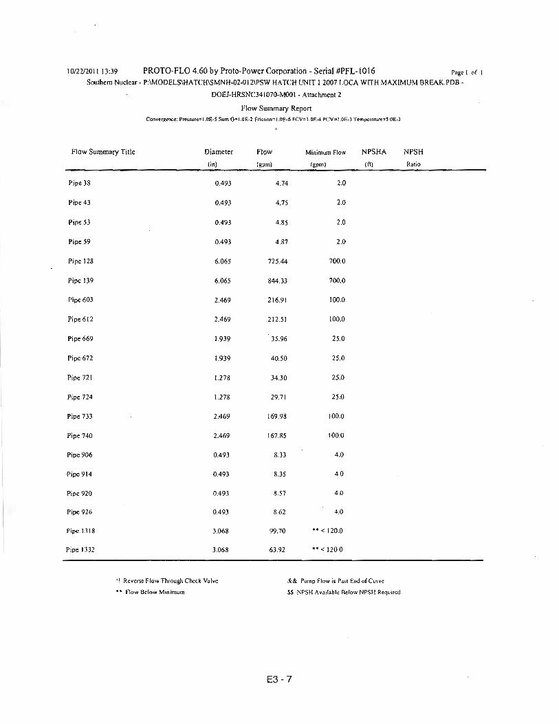
Evaluation: Reference 1 contains the PROTO-FLO file PSW HATCH UNIT 1 2007 LOCA.PDB. This file was used as the basis for this DOEJ. Two new files were created to simulate holes in the 10" Division" supply header to the reactor building. The first case simulates two holes, each equivalent to 2" x 3" (reference Attachment 4), in the Division 1/ supply header to the reactor building, and determines if design flow is still provided to safety-related components that receive PSW. The second case determines the maximum hole size the header can withstand and still provide design flow to safetY-related components that receive PSW. For both cases, a 125 gpm packing leak is assumed as flow out of Node 0020.
Case 1 (PSW HATCH UNIT 1 2007 LOCA with break.PDB) Pipe section 101 in the model is the 10" Division II supply header to the reactor building. In PROTO-FLO, a hole is modeled at a node. In order to model two different holes, pipe section 101.1 and Node 0270A were added since only one hole can be modeled at a single node. The original length of piping was maintained by placing 600 feet in pipe section 101 and 4.2 feet in pipe section 101 .1. At Nodes 0270 and 0270A, a hole was modeled on the Nodal Flow tab.
For a hole 2" x 3", Area for ellipse:;: rrRIR2 :;: rr(212)(3/2) :;: 4.71 in2
[Total through-wall leakage area = (2)(4.71 )=9.42 in2.J
NMP-ES·039-002. Version 2.0 Documentalion of Engineering Judgment.
E3 - 2

DOEJ-HRSNC341070-MOOl Southern Nuclear Operating Company
Since PROTO-FLO models circular holes, determine equivalent diameter of a circular hole: (rrD2)/4 =4.71 D =2.45" With two 2.45" holes in the Division II supply header to the reactor building, PROTO-FLO predicts the following flows to safety-related components:
Table 1 .
Design Flow Predicted Flow Component Pipe (GPM) (GPM) 1 E11C001A 906 4 8.3 1 E11COO18 920 4 8.9
1E11C001C 914 4 8.4 1 E11C001D 926 4 9.0 1P41C001A 38 2 4.7 1P41C0018 53 2 5.1 1P41C001C 43 2 4.8 1P41C001D 59 2 5.1
1T418002A 603 100 217 1T418002B 612 100 212 1T41B003A 733 100 188 1T41B003B 740 100 185 1T41B004A 672 25 40 1T41B004B 669 25 36 1T41B005A 721 25 38 1T41B005B 724 25 33 1R43S001A 139 700 844 1R43S001C 128 700 762
1Z41 B008A (Div. I) 1318 120 100
1Z41 B008C JDiv. II} 1332 120 74
All of the safety-related components receive design flow except the control room HVAC units. The Division I HVAC unit (1Z41-B008A) receives approximately the same flow as indicated in Reference 1. This flowrate was determined to be acceptable as discussed in Reference 1. The Division II HVAC unit (1Z41-B008C) receives 74 gpm which is less than design. This flowrate is judged to be acceptable because:
• The current model (Reference 1) has not been revised since control room HVAC pipe replacement and cleaning; therefore the predicted flow is underestimated.
• Reference 2 evaluated the control room HVAC units for 9JO water and determined the minimum acceptable flow to be 75 gpm. CUrrent river temperature is 66°; therefore, 74 gpm is judged to be acceptable.
• Unit 2 provides backup flow, and credit could be taken for the Unit 2 PSW system to perform its safety function of supplying adequate flow to the control room HVAC units.
2
NMP·ES-039-002. Version 2.0 Documentation or Engineering Judgment.
E3 - 3

DOEJ-HRSNC341070-MOOl Southern Nuclear Operating Conlpany
Case 2 (P5W HATCH UNIT 12007 LOCA with maximum break.PD8) Pipe section 101 in the model is the 10" Division II supply header to the reactor building. A single hole is modeled at Node 0270. Since the control room HVAC units are already receiving less than design flow in Case 1, and those flows have been evaluated for acceptability, the hole size will continue to be increased until the next safety-related component reaches its design flow. By trial and error, with a single 3.97" diameter hole in the Division II supply header to the reactor building, PROTO-FLO predicts the following flows to safety-related components:
Table 2
Design Flow Predicted Flow Component Pipe (GPM) (GPM)
1E11C001A 906 4 8.3
1 E11C001 B 920 4 8.6
1 E11C001 C 914 4 8.4 1E11C001D 926 4 8.6 1P41C001A 38 2 4.7 1 P41C001 B 53 2 4.9
1P41C001C 43 2 4.8 1P41C001D 59 2 4.9
1T41B002A 603 100 217
1T41B002B 612 100 213
1T41B003A 733 100 170
1T41B0038 740 100 168 1T41B004A 672 25 41
1T41B0048 669 25 36 1T41 B005A 721 25 34
1T41B005B 724 25 30
1R43S001A 139 700 844
1R43S001C 128 700 725
1Z41 B008A (Div. !) 1318 120 100 1Z41 B008C (Div. II) 1332 120 64
All of the safety-related components receive design flow except the control room HVAC units. The Division I HVAC unit (1Z41-B008A) receives approximately the same flow as indicated in Reference 1. This flowrate was determined to be acceptable as discussed in Reference 1. The Division II HVAC unit (1Z41-B008C) receives 64 gpm which is less than design. This flowrate is judged to be acceptable because:
• The current model (Reference 1) has not been revised since control room HVAC pipe replacement and cleaning; therefore the predicted flow is underestimated.
• Reference 3 evaluated the control room HVAC units for reduced flow and determined the minimum acceptable flow to be 63.9 gpm at a maximum water temperature of 91.8°
3
NMP·ES·039-002, Version 2.0 Documentation of Engineering Judgment.
E3 - 4

DOEJ-HRSNC341070-MOOl Southern Nuclear Operating Company
cooling water (with margin limitations as discussed in Reference 3). Current river temperature is less than 91.8°; therefore, 64 gpm is judged to be acceptable.
• Unit 2 provides backup flow, and credit could be taken for the Unit 2 PSW system to perform its safety function of supplying adequate flow to the control room HVAC units.
Determine maximum throu~h-wallieakage area based on 3.97" hole: Are8.max = (nD2)/4 = n(3.97 )/4 =12.38 in2
Conclusion: With two 2" x 3" holes (modeled as 2.45" diameter holes for a total through-wall leakage area of 9.42 in2
) in the PSW Division II supply header to the reactor building, PROTO-FLO predicts all . safety-related components will receive design flow, with the exception of the control room HVAC units. By judgement, the control room HVAC units will receive sufficient flow to perform their safety function.
With a maximum through-waUleakage area of 12.38 in2in the Division II supply header to the reactor building (modeled as asingle 3.97" diameter hole), PROTO-FLO predicts all safetyrelated components will receive design flow, with the exception of the control room HVAC units. By judgement, the control room HVAC units will receive sufficient flow to perform their safety function.
List of Attachments:
1. PROTO-FLO summary report for Case 1 2. PROTO-FLO summary report for Case 2 3. Email from Eric King to Scott Kirk, October 22, 2011, with strainer packing leak flow 4. Email from Eric King to Scott Kirk, October 21, 2011, with pipe hole sizes
4
NMp·ES·039-{)()2. Version 2.0 Documentation or Engineering Judgment.
E3 - 5

1012212011 13:22 PROTO-FLO 4.60 by Proto-Power Corporation - Serial #PFL-1016 Page I of 1
Southem Nuclear - P:IModelsIHatchISMNH·02-012\PSW HATCH UNIT I 2007 LOCA with break.POB - Version 4.6
DOEJ-HRSNC341 070-Moo I - Attachment I
Flow Summary Report Convcn<ence: Pressurc=LOE·j Sum Q=1.0E·2 Fric.ion-1.0E·6 FCV-I.OE-4 PCV=1.0E· l Tcmp<r?'un:-50E·3
Flow Summary Title
Pipe 38
Pipe 43
Pipe 53
Pipe 59
Pipe 128
Pipe 139
Pipe 603
Pipe612
Pipe 669
Pipe 672
Pipe 721
Pipe 724
Pipe 733
Pipe 740
Pipe 906
Pipe 914
Pipe 920
Pipe 926
Pipe 1318
Pipe 1332
Diameter
(in)
0.493
0.493
0.493
0.493
6.065
6.065
2.469
2.469
1.939
1.939
1.278
1.278
2.469
2.469
0.493
0.493
0.493
0.493
3.068
3.068
Flow Minimwn Flow NPSHA NPSH
(gpm) (gpm) (ft) Ra.io
4.74 2.0
4.75 2.0
5.07 2.0
5.08 2.0
762.35 700.0
844.42 700.0
216.69 100.0
212 .30 100.0
35.92 25.0
40.46 25.0
37.94 25.0
32.86 25 .0
187.78 100.0
IRS.43 100.0
8.33 4.0
8.35 4.0
8.94 4.0
8.99 4.0
99.62 " < 120.0
74.34 •• < 120.0
II Reve""! Flow ThrouKh Ched Valve && Pump Flow j. Pasl End of Curve
•• Flow Below Minimum SS NPSH AV3ilaoie Below NPSH Required
E3 - 6
10/22/2011 13:39 PROTO-FLO 4.60 by Proto-Power Corporation - Serial #PFL-IOI6 Page 1 of I
Southern Nuclear· P:\MODELSIHATCH\SMNH·02·012\PSW HATCH UNIT I 2007 LOCA WITH MAXIMUM BREAK.PDB •
DOEJ-HRSNC341070-Mool - Atrachment 2
flow Summary Report
Conve11lcnce: PressureaI.O£·S Sum 0-1.0£·2 friolion~1.0E·6 FCV= 1.0F.-I PCV~1.0E·J Tempel1llU ... ~S . OE·3
Flow Summary Title Diameter Flow Minimwn Flow NPSHA NPSH
(in) (gpm) (gpm) (fl) Ratio
Pipe 38 0.493 4.74 2.0
Pipe 43 0.493 4.75 2.0
Pipe 53 0.493 4.85 2.0
Pipe 59 0.493 4.87 2.0
Pipe 128 6.065 725.44 700.0
Pipe 139 6.065 844.33 700.0
Pipe 603 2.469 216.91 100.0
Pipe 612 2.469 212.51 100.0
Pipe 669 1.939 35.96 25.0
Pipc 672 1.939 40.50 25.0
Pipe 721 1.278 34.30 25.0
Pipe 724 1.278 29.71 25.0
Pipe 733 2.469 169.98 100.0
Pipe 740 2.4(j9 167.R5 100.0
Pipe 906 0.493 8.33 4.0
·Pipe914 0.493 8.35 4.0
Pipe 920 0.49.1 8.57 4.0
Pipe 926 0.493 8.62 4.0
Pipe 1318 3.068 99.70 "<120.0
Pipe 1332 3.068 63.92 •• < 120.0
!! Reverse F low Through Check Valve && Pump Flow is Past End of Curve
•• Flow Below Minimum SS NPSH Available Below NPSH Required
E3 -7

DOEJ·HRSNC341070·MOOI Attachment 3 Page 1
Kirk, Scott
From: King, John Eric Sent: Saturday, October 22. 2011 9:29 AM To: Kirk. Scott Subject: PSW Leakage Calculations
2 Holes have been identified in the Unit 1 Division II PSW Reactor Building Header
Hole 1:
Hole 1 is round with 1-1/8" diameter
Flow Q= .6+A*sqrt((2*g*P)/p)
Pressure P = 180 Ibf/in"2
Density p = 0.03657 Ibf/in"3
Gravity g = 32.174 ft/s" 2
Area Hole 1 A :: pi*(d"2)/4 = 0.99402 in"2
Hole 1 Diameter d = 1.125 in
Conversions
12 in/ft
0.004329 gal/in"3
60 s/min
Hole 1 Flow Q= 302 gpm
Hole 2:
Hole 2 is elliptical with a major axis of 2-1/4" and a minor axis of 2"
Flow Q = .6*A*sqrt((2*g*P)/p)
Pressure P :: 180 Ibf/in"2
Dens'ity p = 0.03657 Ibf/in"3
Gravity g:: 32.174 ft/s" 2
Area of 1 hole A = pi*a*b == 3.534292 in"2
Major Axls/2 a = 1.12S in
Minor Axis/2 b = 1 in
Conversions
12 In/ft
0.004329 gal/in"3
60 s/min
Hole 2 Flow Q= 1074 gpm
A packing leak on PSW strainer 1P41D1038
The hole is round with a 2·1/2" diameter
The shaft is round with a 2.393" diameter
Flow Q== .6"A*sqrt((rg*p)/p)
Pressure P= 180 Ibf/in"2
Density p= 0.03657 Ibf/inll 3
Gravity g= 32.174 ft/s"2
Hole Area Ah = pi"(dh"2)/4 4.908739 in"2
Shaft Area As= pi"(dsI\2)/4 :: 4.497543
leak Area AI = Ah-As => 0.411196
E3 - 8

DOEJ-HRSNC341070·MOOl AUachment 3 Page 2
Hole Diameter dh= 2.5 in
Shaft Diameter ds = 2.393 in
Conversions
12 inlft
0.004329 gal/inl\3
60 slmin Strainer Flow Q= 125 gpm
All Leakage Considered
Total Flow Q= 1501 gpm
Leakage Impacts:
Pump Capacity Qp= 8500 gpm From flow model
Required Flow Qr= 4428 gpm From H16012
Leakage Flow QI= 1501 gpm From above
Flow Margin Qm= Up-Qr 4072 gpm
Acceptable if Qm > QI
Is Qm > QI7 Yes
2
. E3 - 9

DOEJ-HRSNC341 OlO-MOO 1 AUachment 4 Page 1
Kirk, Scott
From: King, John Eric Sent: Friday, October 21, 2011 1 :45 PM To: Kirk, Scott Subject: Unit 1 Division II PSW Leak
Scott, Could you help me figure out the effect that a leak would have on the 10" Unit 1 Division II PSW line to the reactor building? There are 2 pits found on the pipe. Both pits have an oval shape and are 2" x 3" in size. There is currently through wall leaks at both pits_ For the operability evaluation, we are assuming that the entire pit is a through wall leak. calculated the flow from this size hole to be 2863 gpm_ See the calculation below:
(2) Holes
Each hole is 2"x3" elliptical
Flow Q= .6*A "sqrt((2 *g* P)/p)
Pressure P= 180 Ibf/in"2
Density p= 0.03657 Ibf/in-'I3
Gravity g= 32_174 ft/s"2 Area of 1 hole A= pi*a*b = 4_712389 in"2
Major Axls/2 a = 1.5 in
Minor Axls/2 b= 1 in
Conversions
12 in/ft
0.004329 gal/in"3
60 s/min
1 Hole => Q= 1432 gpm
2 Holes => Q= 2863 gpm
Thanks, Eric
E3 - 10


![Bibliography - Department of Computer Science and ...rja14/Papers/SE-Bib.pdf · Bibliography 546 [11] C Ajluni, “Two New Imaging Techniques Promise to Improve IC Defect Identification,”](https://static.fdocuments.in/doc/165x107/5ab3a2717f8b9aea528e709f/bibliography-department-of-computer-science-and-rja14papersse-bibpdfbibliography.jpg)