Edwin I. Hatch Nuclear Plant Unit 1 and Unit 2 Emergency Plan
270
Edwin I. Hatch Nuclear Plant Unit 1 and Unit 2 Emergency Plan SOUTHERN A COMPANY
Transcript of Edwin I. Hatch Nuclear Plant Unit 1 and Unit 2 Emergency Plan

Edwin I. Hatch Nuclear Plant Unit 1 and Unit 2 Emergency Plan
SOUTHERN A COMPANY

Version 37 4/15
EDWIN I. HATCH NUCLEAR PLANT
UNIT 1 AND UNIT 2
EMERGENCY PLAN

HATCH NUCLEAR PLANT UNIT 1 AND UNIT 2 EMERGENCY PLAN
TABLE OF CONTENTS
Section Title Page
i Version 37 4/15
PREFACE ..................................................................................................................................... 1
A. ASSIGNMENT OF RESPONSIBILITIES ............................................................................. A-1
B. ONSITE EMERGENCY ORGANIZATION .......................................................................... B-1
C. EMERGENCY RESPONSE SUPPORT AND RESOURCES .............................................. C-1
D. ASSESSMENT ACTIONS ................................................................................................... D-1
E. NOTIFICATION METHODS AND PROCEDURES ............................................................. E-1
F. EMERGENCY COMMUNICATIONS ................................................................................... F-1
G. PUBLIC EDUCATION AND INFORMATION ...................................................................... G-1
H. EMERGENCY FACILITIES AND EQUIPMENT .................................................................. H-1
I. ACCIDENT ASSESSMENT .................................................................................................. I-1
J. PROTECTIVE RESPONSE ................................................................................................. J-1
K. RADIOLOGICAL EXPOSURE CONTROL .......................................................................... K-8
L. MEDICAL AND PUBLIC HEALTH SUPPORT ..................................................................... L-1
M. RECOVERY AND REENTRY PLANNING AND POST-ACCIDENT OPERATIONS ........... M-1
N. EXERCISES AND DRILLS .................................................................................................. N-1
O. RADIOLOGICAL EMERGENCY RESPONSE TRAINING .................................................. O-1
P. RESPONSIBILITY FOR THE PLANNING EFFORT ........................................................... P-1

TABLE OF CONTENTS (Continued)
Section Title Page
ii Version 37 4/15
Appendix 1 - Glossary ........................................................................................................... A1-1
Appendix 2 - Letters of Agreement ........................................................................................ A2-1
Appendix 3 - Means for Providing Prompt Alerting and Notification of the Public Prompt Notification System ................................................................... A3-1
Appendix 4 - Typical Emergency Equipment Lists ................................................................ A4-1
Appendix 5 - Evacuation Time Estimates .............................................................................. A5-1
Appendix 6 - Typical Emergency Implementing Procedures ................................................. A6-1
Appendix 7 - Emergency Operations Facility ......................................................................... A7-1
Appendix 8 - EALs, Initiating Conditions, Threshold Values, and Basis ................................ A8-1

TABLE OF CONTENTS (Continued)
LIST OF TABLES
Table No. Title Page
iii Version 37 4/15
TABLE i - TOOMBS COUNTY GEOGRAPHICAL BOUNDARIES OF PLUME EXPOSURE PATHWAY EVACUATION ZONES ................................................ 2
TABLE ii - APPLING COUNTY GEOGRAPHICAL BOUNDARIES OF PLUME EXPOSURE PATHWAY EVACUATION ZONES ................................................ 3
TABLE iii - JEFF DAVIS COUNTY GEOGRAPHICAL BOUNDARIES OF PLUME EXPOSURE PATHWAY EVACUATION ZONES ................................................ 4
TABLE iv - TATTNALL COUNTY GEOGRAPHICAL BOUNDARIES OF PLUME EXPOSURE PATHWAY EVACUATION ZONES ................................................ 5
TABLE A-1 - RESPONSIBLE INDIVIDUALS OF PRIMARY RESPONSE ORGANIZATIONS ......................................................................................... A-10
TABLE B-1 - MINIMUM STAFFING CAPACITY FOR EMERGENCIES ............................... B-7
TABLE B-2 - EMERGENCY ORGANIZATION ASSIGNMENTS .......................................... B-9
TABLE E-1 - INITIAL NOTIFICATION SYSTEM NORMAL WORKING HOURS AND BACKSHIFT HOURS ....................................................................................... E-3
TABLE J-1 - SHELTERING GUIDANCE REDUCTION IN EXTERNAL GAMMA DOSE FROM PASSING CLOUD ................................................................................. J-5
TABLE J-2 - EVACUATION TIME ESTIMATE SUMMARY ................................................... J-6
TABLE J-3 - INITIAL PROTECTIVE ACTION RECOMMENDATIONS FLOWCHART ......... J-7
TABLE J-4 FOLLOWUP PROTECTIVE ACTION RECOMMENDATIONS FLOWCHART . J-8
TABLE K-1 - EMERGENCY EXPOSURE LIMITS ................................................................ K-3
TABLE A4-1 - CONTROL ROOM EMERGENCY EQUIPMENT (TYPICAL) ........................ A4-1
TABLE A4-2 - TECHNICAL SUPPORT CENTER EMERGENCY EQUIPMENT (TYPICAL) ............................................................................... A4-2
TABLE A4-3 - SIMULATOR BUILDING EMERGENCY EQUIPMENT (TYPICAL) ............... A4-3
TABLE A4-4 - OPERATIONS SUPPORT CENTER EMERGENCY EQUIPMENT (TYPICAL) ..................................................................................................... A4-5

TABLE OF CONTENTS (Continued) Table No. Title Page
iv Version 37 4/15
TABLE A7-1 - TYPICAL CORPORATE EMERGENCY ORGANIZATION ASSIGNMENTS ........................................................................................... A7-16
TABLE A7-2 - CORPORATE EMERGENCY ORGANIZATION TRAINING MATRIX ......... A7-17
TABLE A7-3 - DESCRIPTION OF TRAINING SUBJECT AREAS ...................................... A7-18
TABLE A7-4 - TYPICAL EOF COMMUNICATION CAPABILITY ........................................ A7-19
TABLE OF CONTENTS (Continued)
LIST OF FIGURES
Figure No. Title Page
v Version 37 4/15
FIGURE i - GENERAL VICINITY MAP ................................................................................... 6
FIGURE ii - LOCATION AND VICINITY MAP ......................................................................... 7
FIGURE iii - 10-MILE EMERGENCY PLANNING ZONE ......................................................... 8
FIGURE iv - 50-MILE EMERGENCY PLANNING ZONE ......................................................... 9
FIGURE A-1 - FORMAL INTERFACES AMONG EMERGENCY ORGANIZATIONS ........... A-11
FIGURE A-2 - STATE GOVERNMENT OPERATIONS IN A DECLARED RADIOLOGICAL EMERGENCY .................................................................... A-12
FIGURE A-3 - OPERATIONAL RELATIONSHIPS AMONG COUNTY RESPONSE ORGANIZATIONS ......................................................................................... A-13
FIGURE B-1 - TYPICAL HNP ORGANIZATION CHART ...................................................... B-11
FIGURE B-2 - TYPICAL ALERT, SITE AREA OR GENERAL EMERGENCY RESPONSE ORGANIZATION....................................................................... B-12
FIGURE D-1 - “HOT” INITIATING CONDITION (IC) MATRIX ................................................ D-7
FIGURE D-2 - “COLD” INITIATING CONDITION (IC) MATRIX .............................................. D-8
FIGURE E-1 - TYPICAL EXAMPLE OF EMERGENCY NOTIFICATION FORM .................... E-4
FIGURE E-2 TYPICAL EXAMPLE OF NUCLEAR REGULATORY COMMISSION OPERATIONS CENTER EVENT NOTIFICATION FORM ............................... E-6
FIGURE H-1 - TECHNICAL SUPPORT CENTER TYPICAL LAYOUT PLAN ......................... H-8
FIGURE H-2 - OPERATIONS SUPPORT CENTER TYPICAL LAYOUT PLAN ..................... H-9
FIGURE H-3 - SIMULATOR BUILDING TYPICAL LAYOUT PLAN ...................................... H-10
FIGURE M-1 - TYPICAL RECOVERY ORGANIZATION ........................................................ M-4
FIGURE P-1 - TYPICAL EMERGENCY PLANNING ORGANIZATION .................................. P-3
FIGURE A7-1 ........................................................................................................................ A7-20
FIGURE A7-2 ........................................................................................................................ A7-21

1 Version 37 4/15
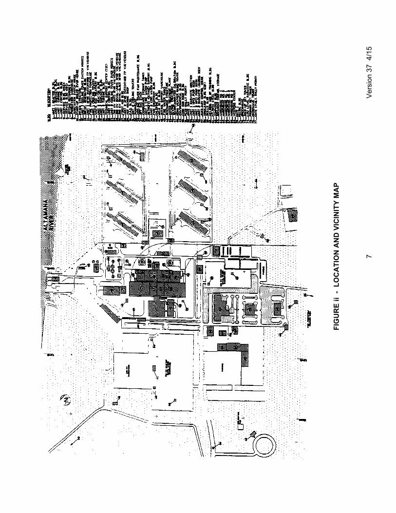
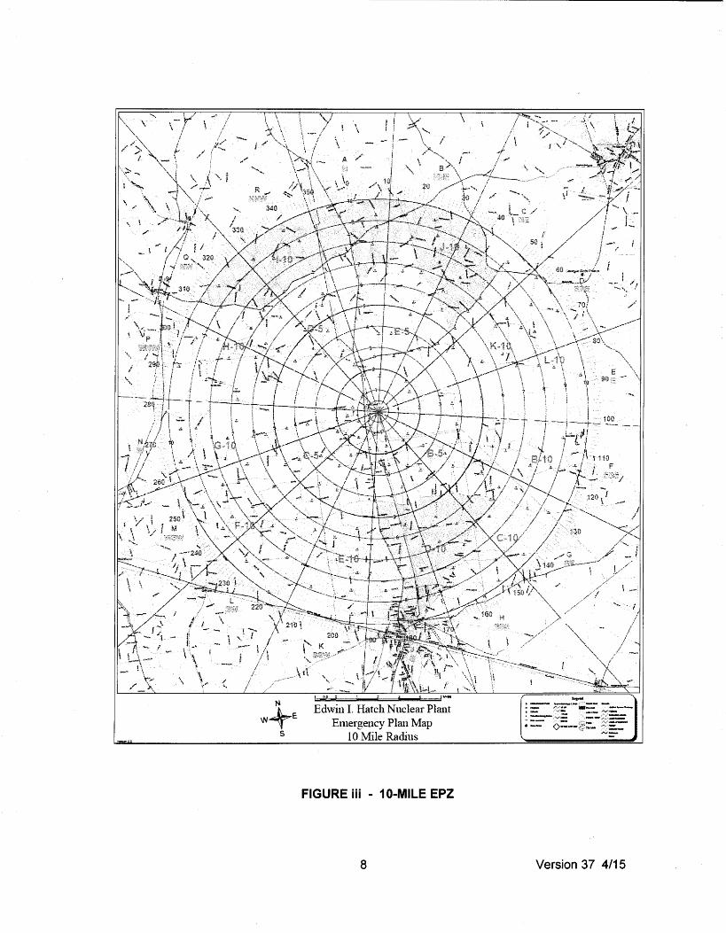
PREFACE The Hatch Nuclear Plant (HNP) is a two-unit boiling water reactor operated by Southern Nuclear Operating Company (SNC) (hereafter referred to as the licensee). The plant is on a 2100-acre site located in Appling County, Georgia, approximately 11 miles north of Baxley, Georgia, on U.S. Highway 1 (Figure i). Figure ii shows the site and locations of the buildings onsite. The locations of the HNP emergency facilities and rally points are shown on Figure ii. This Emergency Plan is applicable to HNP, Units 1 and 2, and to its environs as specified by the emergency planning zones (EPZs): a plume exposure pathway EPZs, which nominally consists of the area within approximately 10 miles of the plant, and an ingestion exposure pathway EPZ, which extends to approximately 50 miles. These distances are taken from the plant stack. The two EPZs are shown in Figures iii and iv. The geographical boundaries of the plume exposure pathway EPZ are shown on Figure iii. These evacuation zones are further detailed in the State Base Plan, Annex A, Table D-1, of each county section (Toombs, Appling, Jeff Davis, and Tattnall). These zones are presented in Tables i through iv. The EPZ for ingestion exposure includes an area within 50 miles of the plant stack, except for portions of Brantley and McIntosh Counties which were excluded to prevent crossing any additional jurisdictional boundaries. Planning for the ingestion exposure pathway is a responsibility of the State of Georgia. More information about the ingestion exposure pathway EPZ can be obtained from the State's Radiological Emergency Plan. The order of the presentation provided herein follows that of the 16 standards delineated in Title 10 Code of Federal Regulations (CFR) Part 50, Section 50.47(b). Appropriate criteria from NUREG-0654, Revision 1, "Criteria for Preparation and Evaluation of Radiological Emergency Response Plans (RERPs) and Preparedness in Support of Nuclear Power Plants," are addressed approximately in the sequence presented in that document. Although this Plan is designed to stand on its own, additional plans expand on matters mentioned here, as identified in Section C. It is to be recognized that this is only a plan and not a prescriptive document. Each incident is a unique event; therefore, this Plan is designed to incorporate the flexibility to tailor the response and meet the emergency. This Plan is supported by a set of implementing procedures. A typical list of these procedures is included as Appendix 6.
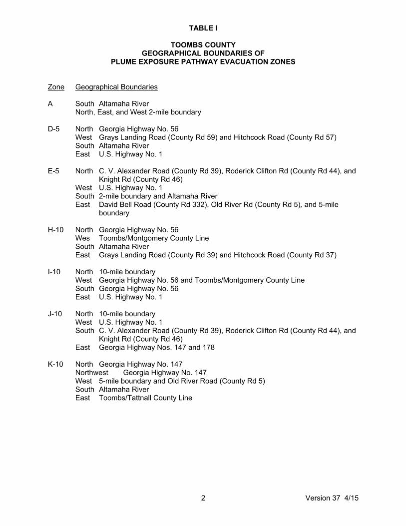
TABLE I
TOOMBS COUNTY GEOGRAPHICAL BOUNDARIES OF
PLUME EXPOSURE PATHWAY EVACUATION ZONES
2 Version 37 4/15
Zone Geographical Boundaries A South Altamaha River
North, East, and West 2-mile boundary D-5 North Georgia Highway No. 56
West Grays Landing Road (County Rd 59) and Hitchcock Road (County Rd 57) South Altamaha River East U.S. Highway No. 1
E-5 North C. V. Alexander Road (County Rd 39), Roderick Clifton Rd (County Rd 44), and
Knight Rd (County Rd 46) West U.S. Highway No. 1 South 2-mile boundary and Altamaha River East David Bell Road (County Rd 332), Old River Rd (County Rd 5), and 5-mile
boundary H-10 North Georgia Highway No. 56
Wes Toombs/Montgomery County Line South Altamaha River East Grays Landing Road (County Rd 39) and Hitchcock Road (County Rd 37)
I-10 North 10-mile boundary
West Georgia Highway No. 56 and Toombs/Montgomery County Line South Georgia Highway No. 56 East U.S. Highway No. 1
J-10 North 10-mile boundary
West U.S. Highway No. 1 South C. V. Alexander Road (County Rd 39), Roderick Clifton Rd (County Rd 44), and
Knight Rd (County Rd 46) East Georgia Highway Nos. 147 and 178
K-10 North Georgia Highway No. 147
Northwest Georgia Highway No. 147 West 5-mile boundary and Old River Road (County Rd 5) South Altamaha River East Toombs/Tattnall County Line

TABLE ii
APPLING COUNTY GEOGRAPHICAL BOUNDARIES OF PLUME EXPOSURE
PATHWAY EVACUATION ZONES
3 Version 37 4/15
Zone Geographical Boundaries A North Altamaha River
South, East, and West - 2-mile boundary B-5 North 2-mile boundary and Altamaha River
West U.S. Highway No. 1 South Lenox Road (County Rd 538) East Davis Landing Road (County Rd 370) and East River Rd (County Rd 375)
B-10 North Altamaha River
West Davis Landing Road (County Rd 370) and East River Rd (County Rd 375) South Fire Tower Road (County Rd 338) and Ten-Mile Road (County Rd 537) East Oscar Tippins Road (County Rd 339) and 10-mile boundary
C-5 North Altamaha River and 2-mile boundary
West Appling/Jeff Davis County Line South Altamaha School Road (County Rd 538) East U.S. Highway No. 1
C-10 North Ten-Mile Road (County Rd 537) and Fire Tower Road (County Rd 338)
West/Northwest - Ten-Mile Road (County Rd 537) South/Southeast - Old Field Cemetery Road (County Rd 341), Manning Williams Rd
(County Rd 342), and 10-mile boundary East Oscar Tippins Road (County Rd 339)
D-10 North Lenox Road (County Rd 538)
West U.S. Highway No. 1 South Georgia Power Company (GPC) transmission line and 10-mile boundary East/Northeast - Ten-Mile Road (County Rd 537)
E-10 North Altamaha School Road (County Rd 538)
West Appling/Jeff Davis County Line and Oil Well Rd (County Rd 37) South GPC transmission line East U.S. Highway No. 1

TABLE iii
JEFF DAVIS COUNTY GEOGRAPHICAL BOUNDARIES OF PLUME EXPOSURE
PATHWAY EVACUATION ZONES
4 Version 37 4/15
Zone Geographical Boundaries F-10 North Altamaha Road (County Rd 203) and Bullard Creek Road by Carters
Cemetery (County Rds 226 and 221) West Graham Rd (County Rd 185) South and East - Jeff Davis/Appling County Line
G-10 North Altamaha River
West Graham Road (County Rd 185) and 10-mile boundary South Altamaha Road (County Rd 203) and Bullard Creek Road by Carters
Cemetery (County Rds 226 and 221) East Jeff Davis/Appling County Line

TABLE iv
TATTNALL COUNTY GEOGRAPHICAL BOUNDARIES OF PLUME EXPOSURE
PATHWAY EVACUATION ZONES
5 Version 37 4/15
Zone Geographical Boundaries L-10 North Georgia Highway No. 147
West Tattnall/Toombs County Line South Altamaha River East 10-mile boundary

6 Version 37 4/15
FIGURE i - GENERAL VICINITY MAP
7
Ver
sion
37
4/1
5
FIG
UR
E ii
- L
OC
AT
ION
AN
D V
ICIN
ITY
MA
P
RE ·•·•· 1 0-MILE EPZ FIGU 1 -
8 Version 37 4/15

Emergency Plan Map 50 Mile Radius
FIGURE iv - 50-MILE EPZ
9 Version 37 4/15
A-1 Version 37 4/15
A. ASSIGNMENT OF RESPONSIBILITIES In the event of a situation at the HNP which requires activation of the emergency response organizations, various Federal, State, local, and private sector organizations may be required to contribute to the emergency response. This section describes the responsibilities of these organizations. Table A-1 lists primary response organizations and the emergency title of the individual in charge. The Licensee The licensee accepts the responsibility of developing and maintaining an effective emergency plan and of maintaining proper preparedness through the development of formal procedures for implementing the Plan as identified in Appendix 6, the training of personnel in accordance with Section O, the procurement of necessary equipment, and the development of relationships with various governmental agencies and private organizations as identified in this section and in Appendix 2. The following tasks are part of the licensee's responsibility: 1. Recognize and declare the existence of an emergency condition.
2. Take corrective actions to mitigate the severity of the accident.
3. Classify the event in accordance with the methodology described in Section D of this Plan.
4. Notify appropriate plant and corporate personnel and offsite authorities.
5. Request additional support, as deemed necessary.
6. Establish and maintain effective communications within HNP and with offsite response groups, as described in Section F.
7. Continuously assess the status of the accident and periodically communicate the status information to the appropriate response groups. This includes the collection and evaluation of onsite and offsite radiological monitoring data.
8. Take protective measures onsite and recommend protective measures to offsite authorities.
9. Monitor and control radiation exposures of all personnel responding to the emergency, under the direction of the licensee.
10. Provide timely and accurate emergency information to the public through press briefings in conjunction with State and local officials.
The licensee emergency response is carried out under the control of the Emergency Director (ED). The onsite organization to support these activities is described in Section B of this Plan. State of Georgia Georgia has developed a RERP on a statewide basis as an integral part of the Georgia Emergency Operations Plan. The Georgia Emergency Operations Plan is an emergency operations plan for all natural disasters, accidents, and incidents, including radiological emergencies at fixed nuclear facilities. It is a plan of action developed for use by

A-2 Version 37 4/15
State and local government officials in preparing for, responding to, and dealing with situations throughout the State. In accordance with Annex No. 12 of the Governor's Executive Order dated June 3, 1983, the Georgia Department of Natural Resources (DNR) has the lead agency responsibility for responding to all peacetime radiological emergency situations throughout Georgia. Under the procedure established by the Georgia Emergency Operations Plan, which was developed pursuant to the Governor's Executive Order, the DNR radiological emergency response team assesses the radiological conditions of an incident at the site and confirms or determines whether a state of emergency exists. Upon being advised that a radiological emergency exists, the Governor declares an emergency condition, which then activates the Georgia Emergency Management Agency (GEMA) authorities to deal with the situation. Under the statutory authority granted to the GEMA, the pre-established plans and procedures of all State agencies and applicable local government organizations are automatically activated and coordinated by the GEMA State Emergency Operations Center (EOC) in Atlanta. In the event of a radiological emergency, GEMA has broad legal authority to take whatever actions are deemed necessary to protect the health and safety of Georgia citizens. This authority includes, but is not limited to, evacuation of people from private property, control of public and private transportation corridors, and utilization of all public facilities in support of efforts to protect life and property. The fundamental legislation providing the basis for emergency response by civil authorities is the Georgia Emergency Management Act of 1981, as amended. This Act in part creates a State Emergency Management Agency (EMA); authorizes the creation of local organizations for emergency management; confers upon the Governor and the executive heads of governing bodies of the State certain emergency powers; and provides the rendering of mutual aid among the political subdivisions of the State, and with other states, and with the Federal Government. Other documents providing bases for emergency response are: 1. Governor's Executive Order, August 25, 1981: Recognizes the Georgia Emergency
Management Act of 1981, which redesignates the State Civil Defense Agency as the GEMA.
2. Georgia Emergency Disaster Operations Plan: Contains the rules and regulations for operations, should an emergency or disaster occur in the State. The Plan is binding on all local governments authorized or directed to conduct emergency management operations and on all State departments or agencies.
3. Radiation Control Act, Georgia Code Annex 88-1301 et seq.: Delegates emergency powers during radiation emergencies to the DNR, Division of Environmental Protection.
4. Georgia Water Quality Control Act of 1974, as amended, Act No. 870.
5. Georgia Air Quality Control Act of 1978, as amended, Act No. 794.
6. Georgia Transportation of Hazardous Materials Act of 1979, Act No. 487.
The duties and responsibilities of the principal and support agencies of the State of Georgia are summarized below. A detailed discussion of the State's response is contained in the Georgia RERP.
A-3 Version 37 4/15
Principal Agencies of the State of Georgia The following State agencies are assigned lead responsibility for radiological emergencies and for overall State preparedness, respectively: 1. GEMA
a. GEMA is responsible for general State emergency planning and exercises, and overall direction and control of emergency or disaster operations as assigned by Executive Order.
b. The Director of Emergency Management as the State Disaster Coordinator coordinates DNR emergency activities with overall State response efforts.
c. On behalf of the Governor, activate all or portions of the Georgia Emergency Operations Plan to provide the necessary overall coordinated response.
d. Provide communications for the State EOC, as required, through the 24-hour radio net, commercial telephone, National Warning System (NAWAS), teletype, or other communications systems. Communication links will be established, in accordance with existing procedures, with the State EOC, as well as with additional State and local emergency response personnel within the plume exposure pathway and 50-mile radius EPZs. These functions will initially be handled from the State EOC in Atlanta and once activated will be transferred to the Forward Emergency Operations Center (FEOC) in Vidalia.
e. Maintain liaison with the DNR Radiation Emergency Coordinator (REC).
f. Activate public emergency warning and/or evacuation procedures, as needed, pursuant to the Georgia Emergency Operations Plan.
g. Assist in performing radiological monitoring and provide radiological monitoring instrumentation.
h. Provide radiological monitoring training assistance.
i. In accordance with the Georgia Emergency Operations Plan, coordinate public information releases in cooperation with State and local agencies.
j. Contact the Governor for National Guard assistance.
DNR
a. DNR is assigned primary responsibility by Executive Order for implementation and administration of the State radiological emergency response function.
b. An REC in the Environmental Protection Division (EPD) interacts with appropriate State, local, and Federal agencies and private organizations to direct all necessary radiation control actions. The REC is on call 24 hours a day and will be notified by the GEMA Duty Officer.

A-4 Version 37 4/15
c. In situations beyond local government control, DNR provides program assistance in the application of available personnel, equipment, and technical expertise, as required.
d. DNR requests State support agency(s) and Federal assistance pursuant to the Georgia Emergency Operations Plan, as required.
e. DNR will escort media personnel within the plume exposure pathway EPZ as conditions allow, if access controls have been established.
f. Dispatch radiation emergency teams, as needed.
g. Perform radiation survey and monitoring, and provide protective equipment, as necessary.
h. Provide technical advice and assist in substance identification.
State Support Agencies The following State agencies are prepared to provide related support of this function as indicated pursuant to the Georgia Emergency Operations Plan: 1. Department of Human Resources
Coordinate emergency health and social assistance pursuant to the Georgia Emergency Operations Plan.
Department of Public Safety
a. As applicable, assume control over the situation until the arrival of radiation safety personnel.
b. Maintain liaison with the DNR REC.
c. Provide communication linkage, as required.
d. Provide land or air transportation, or escort, as available, for radiation safety personnel, other necessary personnel, or equipment.
e. Assist in radiological monitoring, as required.
f. Provide law enforcement assistance for area security or recovery of lost or stolen radioactive material.
g. Coordinate with DNR law enforcement and local police.
h. Assist in public warning or evacuation, as required, including ground and airborne means as available.
i. Assist in area security and control.
j. Provide land or air transportation, as requested, for radiation safety personnel, other necessary personnel, or equipment.

A-5 Version 37 4/15
Department of Agriculture
a. Collect samples of food products, livestock, produce, and dairy products, as necessary.
b. Restrict the sale, production, distribution, and warehousing of livestock, produce, dairy, and processed food products contaminated beyond safe consumption.
c. Assist in disposal of contaminated products.
d. Coordinate these activities with United States Department of Agriculture (USDA) personnel.
e. Maintain liaison with the DNR REC for assessing degree of contamination.
Department of Transportation
a. Assist in traffic control and routing, accident assessment, and recovery operations in transportation incidents.
b. As requested, provide land, air, or water transportation for radiation safety personnel, other necessary personnel, or equipment.
c. Provide communications linkage, as required.
d. Assist State Patrol and DNR law enforcement in security and radioactive material escort, as requested.
e. Provide heavy equipment and personnel, as required.
Forestry Commission
a. Provide land or air transportation, as requested, for radiation safety personnel, other necessary personnel, or equipment.
b. Provide personnel and heavy equipment, as required, to assist in recovery operations.
c. Provide communication linkage, as necessary.
d. Assist with public warning or evacuation, as required, including ground and air operations.
Department of Administrative Services
a. Provide for expedient approval and purchase of equipment and supplies essential to emergency operations.
b. Provide land transportation vehicles for emergency personnel.
c. Provide emergency communications equipment and repair.

A-6 Version 37 4/15
County Emergency Response The area within the plume exposure pathway in the State of Georgia falls within Appling, Jeff Davis, Tattnall, and Toombs Counties. The responsibility for radiological emergency response planning rests with each Chairman of the County Board of Commissioners or the Mayor of his respective jurisdiction. It is this individual's responsibility to initiate actions and provide direction and control at a level consistent with the specific incident. Agencies within each county which have a primary role in radiological emergency planning and response include the EMA, and local law enforcement agencies. Local Emergency Management Agencies (LEMAs) Principal activities include the following: 1. Receive notification from HNP and GEMA.
2. Activate county resources, as necessary, to respond to the emergency.
3. Maintain communications with HNP on emergency situation status.
4. Provide information to other county response elements, the media, and the public.
5. Activate the public notification system, if required.
6. Activate the county EOC.
7. Coordinate the county emergency response activities.
8. Activate and direct operations at the designated reception and care facility.
Local Law Enforcement Agencies Principal activities include the following: 1. Control access to the plume exposure pathway EPZ.
2. Provide traffic control and law enforcement measures in the event of an evacuation.
3. Act as receiver of notification from HNP and GEMA.
Others Other county resources, including the Fire Department, Health Department, and Public Works Department, may be mobilized as described in Annex A to the Georgia RERP. Medical Support Plant Hatch has established agreements with the Appling Ambulance Service and the Meadows Regional Medical Center for the transportation of injured personnel, including people who may be radioactively contaminated, to hospital facilities for treatment. Agreements with the Appling General Hospital in Baxley, the Meadows Regional Medical Center in Vidalia, and a contract with a medical consulting group have also been established for treatment of injured and

A-7 Version 37 4/15
contaminated/irradiated individuals. Support provided includes, but is not limited to, emergency medical services, ambulances, and emergency medical technicians. Request for medical support will be made by the control room or site security to the Appling County 911 center, Appling or Toombs County EOCs, or the Incident Command Post, as applicable, based on the nature and timing of the event. Copies of these agreements are maintained in the SNC document management system and are included by reference in Appendix 2. Fire Support Plant Hatch has established an agreement with the Appling County EMA to provide, upon request, offsite fire support to the HNP Fire Brigade. Support provided includes, but is not limited to, firefighters and firefighting equipment. Request for fire support will be made by the control room or site security to the Appling County 911 center, Appling County EOC, or the Incident Command Post, as applicable, based on the nature and timing of the event. A copy of this agreement is maintained in the SNC document management system and is included by reference in Appendix 2. Private Sector Organizations 1. Bechtel Power Corporation
The licensee has established an agreement with Bechtel Power Corporation to obtain engineering and construction services which may be required following an accident. Bechtel's assistance will not be required during the early stages of the emergency response but is more likely to be requested during recovery activities.
2. General Electric Company (GE)
The licensee has established an agreement with GE to obtain general services related to nuclear steam supply system (NSSS) operations during and following an accident situation. GE provides a capability to respond on a 24-hour-a-day basis.
3. Voluntary Assistance Group
The licensee is a signatory to two comprehensive agreements among electric utility companies: the Nuclear Power Plant Emergency Response Voluntary Assistance Agreement and the Voluntary Assistance Agreement By and Among Electric Utilities Involved in Transportation of Nuclear Materials.
Federal Government Support The resources of the Federal agencies appropriate to the emergency condition will be made available in accordance with national response plans. The ED is specifically authorized to request Federal assistance on behalf of the licensee under the provisions of this Plan. In addition to the Nuclear Regulatory Commission (NRC), other agencies which may become involved are the Department of Energy (DOE), the Federal Emergency Management Agency (FEMA), the Environmental Protection Agency (EPA), the Department of Health and Human Services, the Department of Transportation, and the Department of Agriculture. Concept of Operations
A-8 Version 37 4/15
The emergency preparedness (EP) program for HNP requires the coordinated response of several organizations. The emergency organization for HNP is described in detail in Section B of this Plan. The ED is the key individual in the HNP emergency organization; one of his nondelegable responsibilities is the decision to notify the NRC and those authorities responsible for offsite emergency measures. The interfaces among the emergency organizations are shown on Figure A-1. Continuous Communication Capability The ED initiates the activation of various emergency response organizations by contacting the State of Georgia, county EMAs, and the NRC. All of these organizations can be contacted 24 hours a day. The State of Georgia and counties surrounding HNP have a continuously manned communication link, the Emergency Notification Network (ENN), for the purpose of receiving notification of a radiological emergency. The preferred contact for the county is the EMA Director. In the event of inability to contact the EMA Director, the designated 24-hour point of contact for each county will be contacted so the county officials can be notified. The Federal agencies which may be requested by HNP to provide assistance can be notified by contacting the NRC on a dedicated communication link, the Emergency Notification System (ENS). The capability for 24-hour-per-day alerting and notification of offsite response organizations and plant emergency personnel is further described in Section E. State and County Operations The State and County responses are conducted in accordance with the following framework, as presented in the Georgia RERP: 1. As the lead radiation emergency response agency, the DNR is involved in virtually all
peacetime radiation emergencies, regardless of severity, due to its assigned responsibility and the probable requirements for special techniques, equipment, and expert personnel.
2. As the designated agency to administer NRC Agreement State Programs, the Department of Natural Resources is the principal radiation emergency response support agency due to the probable requirements for special techniques, equipment, and expert personnel.
3. As the overall State coordinating agency, GEMA coordinates the DNR emergency response activities with State, County, and municipal agencies and departments, as stated in the Georgia Emergency Operations Plan.
4. To the extent available, local resources, personnel authority, and emergency plans are employed in response to radiation emergencies.
5. When requested to assist in response and recovery efforts to radiation emergencies, personnel from local and other State agencies are normally expected to perform functions and activities in which they have expertise but may perform limited radiation safety functions under the guidance of the DNR REC.
6. In the case of occurrences of limited severity and complexity, direction and control of response and recovery operations will be assumed by the DNR REC; GEMA will be kept informed of conditions in order to facilitate GEMA response and Georgia Emergency Operations Plan activation, as deemed necessary.

A-9 Version 37 4/15
7. When necessitated by the magnitude and severity of an occurrence, GEMA will activate the Georgia Emergency Operations Plan and coordinate overall response and recovery operations, with the DNR REC coordinating radiation protection activities through the State Disaster Coordinator.
The organizational structures for State and County operations are illustrated on Figures A-2 and A-3, respectively. The Georgia RERP and Annex A to the Plan provide the bases for a 24-hour-a-day radiological emergency response capability for extended periods.

A-10 Version 37 4/15
TABLE A-1
RESPONSIBLE INDIVIDUALS OF PRIMARY RESPONSE ORGANIZATIONS
Organization
Individual in Charge of Emergency Response
SNC ED State of Georgia Governor GEMA State Disaster Coordinator Georgia DNR REC Appling, Jeff Davis, Tattnall, and Toombs Counties
Chairman, County Board of Commissioners
LEMAs EMA Directors Local Law Enforcement Agencies Sheriff/Chief of Police Georgia Department of Human Resources Environmental Radiation Specialist of the
Radiological Health Section

A
-11
Ver
sion
37
4/1
5
FIG
UR
E A
-1
FO
RM
AL
INT
ER
FA
CE
S A
MO
NG
EM
ER
GE
NC
Y O
RG
AN
IZA
TIO
NS

A
-12
Ver
sion
37
4/1
5
FIG
UR
E A
-2
ST
AT
E G
OV
ER
NM
EN
T O
PE
RA
TIO
NS
IN
A D
EC
LA
RE
D R
AD
IOL
OG
ICA
L E
ME
RG
EN
CY

A
-13
Ver
sion
37
4/1
5
F
IGU
RE
A-3
-
OP
ER
AT
ION
AL
RE
LA
TIO
NS
HIP
S A
MO
NG
CO
UN
TY
RE
SP
ON
SE
OR
GA
NIZ
AT
ION
S

B-1 Version 37 4/15
B. ONSITE EMERGENCY ORGANIZATION Initial staffing of the onsite HNP emergency organization is provided from personnel normally stationed at the site. For reference throughout this section, the organizational chart for the HNP staff is presented in Figure B-1. If the need arises, this staff is augmented substantially by the addition of other licensee personnel and by personnel from other organizations. This section includes a description of the emergency duties of the normal shift complement, a discussion of the manner in which emergency assignments are to be made, a listing of additional support personnel upon whom the licensee can rely, and a description of the relationships between onsite and offsite response activities. Normal Plant Organization The organizational structure shown on Figure B-1 represents the pool of personnel normally available, approximately 900 people. The operating crew for each unit includes one Shift Supervisor (SS), two Nuclear Plant Operators (NPOs), and two System Operators (SOs). A Shift Manager (SM) and a Shift Technical Advisor (STA) are also on shift during operation. In addition, personnel from the Health Physics (HP) Chemistry, Maintenance, and Security Departments are continuously onsite. Emergency Organization Once an emergency condition is determined and initial mitigating actions are underway, the ED has the responsibility to classify the event in accordance with the emergency classification system (described in Section D). Classification of an event into one of the four emergency categories [Notification of Unusual Event (NUE), Alert, Site Area Emergency, or General Emergency] activates the HNP emergency organization. The extent to which the onsite HNP emergency organization is activated depends upon the severity of the situation. Table B-1 provides a summary of personnel available on shift and those who would be available within approximately 60 min. of notification. A copy of this On-Shift Staffing Analysis, which forms the technical basis for Table B-1, Minimum Shift Staffing, is maintained in the SNC document management system. Reference OSA-HNP-001. For an NUE, the ED assigns responsibility for making the appropriate notifications and directing the proper response; but no further activation of the emergency organization is required. If the event is classified as an Alert, the Technical Support Center (TSC) and the Operations Support Center (OSC) are activated. Figure 2 shows the emergency organization when fully activated. Corporate personnel who may report to the plant site are provided the necessary training and are integrated into the HNP emergency organization, as necessary. Relationships among the HNP emergency organization and other elements of emergency response are shown on Figure A-1. During hostile action, ERO members would likely not have access to the onsite emergency response facilities. A security related emergency may delay the ordering of facility activation in order to protect plant personnel from the security threat. The decision to delay activation of the facilities will be made by the Emergency Director. In such cases, offsite ERO personnel will be

B-2 Version 37 4/15
directed to an alternative facility to minimize delays in overall site response by permitting ERO assembly without exposing responders to the danger of hostile action. Emergency Organization Responsibilities Following an Alert or higher emergency declaration, the positions shown on Figure B-2 will be filled by emergency response personnel as discussed below. 1. ED
The ED has the authority, management ability, and knowledge to assume the overall responsibility for directing HNP staff in an emergency situation. Initially this position is filled by the SM or any ED qualified SS. Any of these persons will assume the ED position until the Plant Manager, the Regulatory Affairs Manager, the Operations Manager, the Engineering Director, the Maintenance Manager, the Vice President-Hatch, or other qualified EDs can arrive onsite and receive an adequate turnover. The ED manages the following activities for the duration of the emergency:
• Notification and communication: directs the notification of HNP and licensee personnel and communications with offsite authorities regarding all aspects of emergency response.
• Emergency response facilities (ERF): oversees the activation and staffing and requests additional assistance, as needed.
• Emergency operations: has authority over those actions taken to mitigate the emergency condition or reduce the threat to the safety of plant personnel or the public, including the recommendation of protective actions to offsite authorities.
• Emergency services: provides overall direction for management of procurement of site-needed materials, equipment, and supplies; documentation; accountability; and security functions.
• Emergency operations planning: provides overall direction for the management of planning for procedure, equipment, and system development to support emergency operations.
• Discretionary authority: may tailor the emergency organization to fit the specific staffing needs on a case-by-case basis.
The ED may not delegate the following responsibilities:
• The decision to notify offsite emergency response agencies.
• The decision to recommend protective actions to offsite authorities.
• Declaration of emergency classifications.
• Authorization for plant personnel to exceed 10 CFR 20 radiation exposure limits.

B-3 Version 37 4/15
• The decision to terminate the emergency.
• The decision to request Federal assistance.
• The decision to dismiss nonessential personnel from the site at an Alert classification level or higher.
• Authorization of the use of potassium iodide.
The ED may operate from the Control Room or the TSC at his discretion. He may act as the TSC Manager during the early phases of emergency response, as needed. It is the intent of SNC that the ED will be transferred from the Control Room as soon as practicable.
TSC Staff
a. TSC Manager
The TSC Manager performs the following activities:
• Coordinates inputs and recommendations from technical and corrective action advisors.
• Directs onsite HNP emergency personnel involved in restoration of the plant to a safe condition.
• Provides technical assistance and operations guidance to Control Room personnel.
• Directs TSC staff in analysis of problems, design and planning for temporary modifications, and development of temporary emergency operating procedures (EOP).
• Recommends protective actions to the ED based on plant conditions.
• Provides the ED recommendations on emergency classifications.
b. Support Coordinator (TSC)
The Support Coordinator in the TSC directs the clerical and logistic activities in the TSC. He ensures support staff, including Clerks and Communicators/Recorders, are available in sufficient numbers and that office supplies, drawings, and other documents are available to TSC personnel. He ensures transportation and communication needs are satisfied. When the EOF is activated, the Support Coordinator in the TSC interfaces with the Support Coordinator in the EOF.
c. Engineering Supervisor
The Engineering Supervisor directs a staff of engineers with expertise in reactor engineering, thermal and hydraulic analysis, instrumentation and control, and mechanical and electrical systems. He directs the analysis of plant problems and provides recommendations for plant modifications to mitigate the effects of the accident.

B-4 Version 37 4/15
d. Maintenance Supervisor
The Maintenance Supervisor manages the planning and coordination of repair, damage control, and plant modification activities. He works closely with the Engineering Supervisor in planning for plant modifications and repairs.
e. Operations Supervisor
The Operations Supervisor analyzes problems associated with systems operations and provides recommendations for procedures for mitigating the emergency situation.
f. HP/Chem Supervisor
The HP/Chem Supervisor makes radiological accident assessments and provides support for analyzing radiological changes during the event.
g. Security Supervisor
The Security Supervisor has the following responsibilities: • Processing of personnel who require authorization to enter the site.
• Requesting assistance through the ED from civic law enforcement authorities, if required.
• Ensuring site accountability and access control are maintained.
OSC Staff
a. OSC Manager
The OSC Manager receives direction from the TSC to dispatch emergency teams (e.g., fire fighting, rescue, first aid, repair, etc.) to prescribed areas of the plant or site. The OSC Manager directs composition of the teams to ensure appropriately qualified personnel are assigned. In particular, he ensures proper HP coverage is provided. The OSC Manager ensures specific instructions are provided to the team leaders and maintains communications with the teams to monitor the status of their activities.
b. OSC Personnel
Selected personnel report to the OSC, as directed. Emergency personnel from the Maintenance, the Operations, and the HP/Chemistry Departments are directed to report to the OSC. The following emergency teams are formed, as necessary: • Fire brigade.
• Search and rescue.
• Repair.

B-5 Version 37 4/15
• Post-accident sampling.
• Internal survey.
• Field monitoring.
• Rally point.
Each OSC team is headed by a designated team leader, who maintains communication with the OSC. The field monitoring teams are dispatched to the Simulator Building to prepare for field monitoring activities. These teams are under the control of the on-shift HP/Chem Foreman until relieved by the HP/Chem Supervisor in the TSC or the Dose Assessment Supervisor in the EOF.
EOF Staff
The description of the EOF staff positions is contained in Appendix 7. Emergency Organization Assignments Table B-2 identifies by title the individuals who will fill the key emergency positions. No individual listed in Table B-2 is identified as the primary candidate for more than one emergency position. Some primary candidates are identified as alternates for other emergency positions. It is expected that one person may occupy up to two emergency positions within the same emergency. During the first 6 hours of an emergency, the emergency response positions will be manned by qualified available personnel. A sufficient number of people are identified to ensure that all emergency positions listed on Table B-2 will be filled on a 24-hour-a-day basis. Alternative Facility Staff The ERO staff will be directed to report to the Alternative Facility during a security related event or other events that preclude onsite access. This facility functions as a staging area for augmentation of emergency response staff and provides the capability for communication with the EOF, control room, and plant security. From this facility the ERO will support event response by performing engineering assessment activities, including damage control team planning and preparation for return to the site. The command and control function will remain with the ED in the control room until relieved by another onsite ED. Dose assessments and offsite notifications will be performed by the EOF. Other Support Services 1. Contractor Support
Arrangements have been made to obtain support services from Bechtel Power Corporation, and GE, if required. Support capability has been available through the joint efforts of the SNC corporate office staff and Southern Company Services (SCS) architect-engineering and service company. As a result of the consolidation of SCS and SNC nuclear expertise, and in addition to being the licensee, SNC also serves as its own architect/engineer and performs the functions previously performed by SCS. The EOF

B-6 Version 37 4/15
Support Coordinator initially contacts these organizations to arrange for the required assistance.
2. Medical Assistance
Agreements are in place with the Appling General Hospital, the Meadows Regional Medical Center, and the Appling and Toombs Counties Ambulance Services (Appendix 2) and a contract with a medical consulting group to provide assistance for injured personnel, including cases involving radioactive contamination. This assistance is requested whenever necessary in accordance with plant procedures.
3. Offsite Fire Assistance
Agreements are in place with the Appling County EMA to provide onsite HNP Fire Brigade in the unlikely event of a fire requiring offsite assistance. This assistance is requested according to plant procedures.
4. Agency Support
Assistance may be requested from the State of Georgia or the Federal agencies. Section A of this Plan describes the assistance that may be requested. Any requests for aid are made by the ED.
Interfaces Among Response Groups Section A, Figure A-1, illustrates the integrated organization for response to an emergency at HNP.

B
-7
Ver
sion
37
4/1
5
TA
BL
E B
-1 (
SH
EE
T 1
OF
3)
M
INIM
UM
ST
AF
FIN
G C
AP
AC
ITY
FO
R E
ME
RG
EN
CIE
S
M
ajor
Fun
ctio
nal A
rea
Maj
or T
asks
E
xper
tise
or T
ypic
al
Pos
ition
Titl
e O
n S
hift
Aug
men
tatio
n in
60
min
(a)
Pla
nt o
pera
tions
and
as
sess
men
t of o
pera
tiona
l a
spec
ts.
S
M
SS
N
PO
S
O
1(c)
2 2 2
_ _ _ _
Em
erge
ncy
dire
ctio
n an
d co
ntro
l (E
D).
O
vera
ll m
anag
emen
t of
emer
genc
y or
gani
zatio
n.
SM
, SS
, Pla
nt M
anag
er, R
egul
ator
y A
ffairs
Man
ager
, Ope
ratio
ns M
anag
er,
Mai
nten
ance
Man
ager
, Vic
e P
resi
dent
-H
atch
, or
othe
r de
sign
ated
qua
lifie
d pe
rson
s.
-(c)
1
N
otifi
catio
n/
com
mun
icat
ion.
N
otifi
catio
n of
Lic
ense
e, F
eder
al,
Sta
te, a
nd L
ocal
per
sonn
el.
Nuc
lear
Pla
nt O
pera
tor
or o
ther
trai
ned
pers
onne
l (E
NN
Com
mun
icat
or).
1
2
R
adio
logi
cal a
ccid
ent
asse
ssm
ent a
nd s
uppo
rt o
f op
erat
iona
l acc
iden
t as
sess
men
t.
EO
F d
irect
ion.
O
ffsite
dos
e as
sess
men
t. E
OF
Man
ager
. R
P/C
hem
istr
y su
perv
isio
n.
_ _ 1 1
Offs
ite s
urve
ys.
RP
/Che
mis
try
Tec
hnic
ians
and
2
2
Ons
ite (
out o
f pla
nt)
surv
ey.
othe
r tr
aine
d pe
rson
nel.
1 1
In
-pla
nt s
urve
y.
2
1
C
hem
istr
y/ra
dioc
hem
istr
y.
RP
/Che
mis
try
Tec
hnic
ians
or
othe
r tr
aine
d pe
rson
nel.
1 1

B
-8
Ver
sion
37
4/1
5
TA
BL
E B
-1 (
SH
EE
T 2
OF
3)
M
INIM
UM
ST
AF
FIN
G C
AP
AC
ITY
FO
R E
ME
RG
EN
CIE
S
M
ajor
Fun
ctio
nal
Are
a
M
ajor
Tas
ks
Exp
ertis
e or
Typ
ical
P
ositi
on T
itle
On
Shi
ft A
ugm
enta
tion
in 6
0 m
in (a
)
Pla
nt s
yste
m e
ngin
eerin
g,
repa
ir, a
nd c
orre
ctiv
e ac
tions
.
Tec
hnic
al s
uppo
rt
(incl
udin
g co
re/ t
herm
al h
ydra
ulic
s).
ST
A.
Rea
ctor
Eng
inee
r (C
ore/
The
rmal
H
ydra
ulic
s).
Ele
ctric
al.
Mec
hani
cal.
1 - - -
- 1 1 1
R
epai
r an
d co
rrec
tive
ac
tions
. M
echa
nica
l ma
inte
nan
ce.
Ele
ctric
al m
aint
ena
nce.
In
stru
men
tatio
n an
d C
ontr
ol T
echn
icia
n.
Ope
ratio
ns D
ept
. Sys
tem
Ope
rato
r.
1 2 1 1
1 1 1 -
Fire
fight
ing.
F
ire B
riga
de L
ead
er.
Fire
Brig
ade
. S
hift
supp
ort S
uper
viso
r (S
RO
).
Ope
ratio
ns D
ept
. Sys
tem
Ope
rato
rs.
1 4
Loca
l su
ppor
t
S
ite a
cces
s co
ntro
l and
pe
rso
nne
l acc
oun
tab
ility
S
ecur
ity, c
omm
unic
atio
ns, a
nd
pers
onn
el a
cco
unta
bili
ty.
Sec
urity
per
sonn
el.
Per
S
ecur
ity
Pla
n.
P
rote
ctiv
e ac
tions
(in
-pla
nt).
·
Rad
iatio
n pr
ote
ctio
n:
· A
cces
s co
ntro
l. ·
RP
cov
erag
e fo
r re
pair,
cor
rect
ive
actio
ns, s
earc
h a
nd r
escu
e, fi
rst a
id,
and
fire
fight
ing.
·
Per
son
nel m
on
itorin
g.
· D
osim
etry
.
RP
/Che
mis
try
Tec
hnic
ians
or
oth
er tr
ain
ed p
erso
nne
l. 4(b
) 2
R
escu
e op
erat
ions
an
d fir
st a
id.
-
-
-
-
2(b)
Loca
l su
ppor
t
TO
TA
LS
___
__
25(d
) __
___
18

B
-9
Ver
sion
37
4/1
5
TA
BL
E B
-1 (
SH
EE
T 2
OF
3)
M
INIM
UM
ST
AF
FIN
G C
AP
AC
ITY
FO
R E
ME
RG
EN
CIE
S
NO
TE
S:
a.
The
60
min
ref
eren
ced
here
rep
rese
nt a
n ap
prox
imat
e af
ter
hour
s st
aff a
ugm
enta
tion
time.
Dur
ing
norm
al b
usin
ess
hour
s,
on-s
hift
pers
onne
l inc
lude
thos
e in
divi
dual
s de
note
d in
the
60-m
in c
olum
n.
b.
May
be
pro
vide
d by
shi
ft pe
rson
nel a
ssig
ned
othe
r fu
nctio
ns.
c.
The
Shi
ft M
anag
er b
ecom
es th
e E
D u
ntil
relie
ved
by th
e au
gmen
ted
staf
f.
d.
The
tot
al f
or o
n sh
ift p
erso
nnel
doe
s no
t in
clud
e th
ose
num
bers
mar
ked
with
the
(b)
sup
ersc
ript a
s th
ese
posi
tions
are
co
llate
ral d
utie
s of
oth
er p
ositi
ons
coun
ted
in t
he to
tal.

B
-10
Ver
sion
37
4/1
5
TA
BL
E B
-2 (
SH
EE
T 1
OF
2)
E
ME
RG
EN
CY
OR
GA
NIZ
AT
ION
AS
SIG
NM
EN
TS
Typ
ical
Nor
mal
Pos
ition
by
Titl
e (a
)
Em
erge
ncy
Pos
ition
P
rimar
y A
ltern
ate(
s)
E
D(b
) P
lant
Man
ager
R
egul
ator
y A
ffairs
Man
ager
, Eng
inee
ring
Dire
ctor
, O
pera
tions
Man
ager
, Mai
nten
ance
Man
ager
, Vic
e P
resi
dent
-H
atch
.
TS
C M
anag
er
Out
age
and
Sch
edul
ing
Man
ager
E
ngin
eerin
g S
uppo
rt M
anag
er, D
esig
n M
anag
er, T
rain
ing
Man
ager
, Nuc
lear
Ope
ratio
ns T
rain
ing
Sup
ervi
sor,
Hea
lth
Phy
sics
Man
ager
, Tec
hnic
al S
ervi
ces
Man
ager
.
Sup
port
Coo
rdin
ator
(E
OF
) R
efer
to A
ppen
dix
7.
Ref
er to
App
endi
x 7.
Eng
inee
ring
Sup
ervi
sor
Eng
inee
ring
Sup
ervi
sor
Eng
inee
ring
Sup
port
Man
ager
, Des
ign
Man
ager
, Tec
hnic
al
Ser
vice
s M
anag
er, E
ngin
eerin
g S
uper
viso
r(s)
, Eng
inee
r,
Prin
cipa
l, E
ngin
eer-
Sr.
Mai
nten
ance
Sup
ervi
sor
Mai
nten
ance
Sup
erin
tend
ent
Ma
inte
nanc
e T
eam
Lea
der(
s), M
aint
enan
ce E
ngin
eer.
Ope
ratio
ns S
uper
viso
r O
pera
tions
Sup
erin
tend
ent
Ope
ratio
ns S
uper
inte
nden
t, de
sign
ated
SM
s.
HP
and
Che
mis
try
Sup
ervi
sor
Che
mis
try
Man
ager
H
P S
uper
viso
r, C
hem
Sup
ervi
sor,
Hea
lth P
hysi
cist
, Pla
nt
Che
mis
t.
OS
C M
anag
er
Mai
nten
ance
Tea
m L
eade
r(s)
S
ched
ulin
g S
uper
viso
r, P
lann
ing
Sup
ervi
sor,
Mai
nten
ance
T
eam
Lea
der(
s), A
ssis
tant
Tea
m L
eade
r.
E
OF
Man
ager
R
efer
to A
ppen
dix
7.
Ref
er to
App
endi
x 7.
Sup
port
Coo
rdin
ator
(T
SC
) D
ocum
ent C
ontr
ol S
uper
viso
r H
uman
Res
ourc
es A
dmin
istr
ativ
e S
uper
viso
r, A
dmin
istr
ativ
e A
ssis
tan
t(s)
.

B
-11
Ver
sion
37
4/1
5
TA
BL
E B
-2 (
SH
EE
T 2
OF
2)
E
ME
RG
EN
CY
OR
GA
NIZ
AT
ION
AS
SIG
NM
EN
TS
Typ
ical
Nor
mal
Pos
ition
By
Titl
e (a
)
Em
erge
ncy
Pos
ition
P
rimar
y A
ltern
ate(
s)
D
ose
Ass
essm
ent
Sup
ervi
sor
Ref
er to
App
endi
x 7.
R
efer
to A
ppen
dix
7.
S
ecur
ity S
uper
viso
r S
ecur
ity (
Site
) M
anag
er-N
ucle
ar
Sec
urity
Sup
ervi
sor,
Nuc
lear
Sec
urity
C
apta
in, S
ecur
ity S
uper
viso
r Li
eute
nant
-Nuc
lear
.
NO
TE
S:
a.
The
se p
ositi
ons
are
typi
cal t
o th
e em
erge
ncy
resp
onse
pos
ition
. C
hang
es in
ass
ignm
ent m
ay
be
mad
e as
lo
ng a
s th
e in
divi
dual
qua
lifie
s fo
r th
e ne
w a
ssig
nmen
t. T
he a
nnua
l rev
iew
/rev
isio
n (a
s ne
cess
ary)
to th
e P
lan
will
ref
lect
any
cha
nges
in e
mer
genc
y re
spon
se a
ssig
nmen
t. b.
T
his
posi
tion
may
be
fille
d in
itial
ly b
y an
on-
shift
indi
vidu
al.
The
mos
t sen
ior
mem
ber
of p
lant
or
SN
C m
anag
emen
t who
is q
ualif
ied
may
ass
ume
this
pos
ition
upo
n ar
rival
at H
NP
.

B
-12
Ver
sion
37
4/1
5
FIG
UR
E B
-1
TY
PIC
AL
HN
P O
RG
AN
IZA
TIO
N C
HA
RT

B
-13
Ver
sion
37
4/1
5
FE
DE
RA
L, S
TA
TE
& O
TH
ER
OF
FS
ITE
AG
EN
CIE
S
EO
FM
AN
AG
ER
RE
FE
R T
OA
PP
EN
DIX
7
EM
ER
GE
NC
YD
IRE
CT
OR
OS
CM
AN
AG
ER
TS
CM
AN
AG
ER
SH
IFT
MA
NA
GE
R
CO
MM
UN
ICA
TO
RS
*SY
ST
EM
OP
ER
AT
OR
S
CLERK
COMMUNICATORS
SUPPORT COORDINATOR (TSC)
ENGINEERING SUPERVISOR
MAINTENANCE SUPERVISOR
OPERATIONS SUPERVISOR
HP/CHEMISTRY SUPERVISOR
SECURITY SUPERVISOR
HP/CHEMISTRY
FIRE BRIGADE (AS NEEDED)
SEARCH/RESCUE
OPERATIONS SUPPORT
INTERNAL SURVEY
MAINTENANCE
SH
IFT
SU
PE
RV
ISO
RS
HIF
TT
EC
HN
ICA
LA
DV
ISO
R
SH
IFT
SU
PP
OR
TS
UP
ER
VIS
OR
PL
AN
TO
PE
RA
TO
RS
*MA
Y B
E D
ISP
AT
CH
ED
FR
OM
TH
E C
ON
TR
OL
RO
OM
/OR
OS
C.
FIG
UR
E B
-2
TY
PIC
AL
AL
ER
T, S
ITE
AR
EA
OR
GE
NE
RA
L E
ME
RG
EN
CY
RE
SP
ON
SE
OR
GA
NIZ
AT
ION

C-1 Version 37 4/15
C. EMERGENCY RESPONSE SUPPORT AND RESOURCES State and Local Governmental Support The State of Georgia through the GEMA has the lead agency responsibility for responding to emergency situations throughout Georgia. Under the procedure established by the Natural Disaster Operation Plan, which was developed pursuant to the Governor's Executive Order, the DNR radiological emergency response team, under the direction of GEMA, assesses the radiological conditions at the site of an incident and determines whether a state of emergency exists. Upon GEMA's advising the Governor of the State of Georgia that a radiological emergency exists, the Governor declares an emergency condition which activates the GEMA. The LEMAs may activate independently or prior to the Governor's declaration of a state of emergency. However, the LEMA must be activated in conjunction with the GEMA activation. [(Reference the State of Georgia RERP).] The concept of operations for which the State of Georgia discharges this responsibility, together with a discussion of action responsibilities assigned to various State/County governmental agencies is contained in the State of Georgia REP, and Annex A to the REP, HNP. For a complete discussion of authority, assigned responsibilities, capabilities, and activation and communication arrangements, refer to these plans. Agreements are in place with the State of Georgia, Appling County, Toombs County, Tattnall County, and Jeff Davis County to provide available resources and equipment to support the mitigation and response to an emergency at Plant Hatch to include Hostile Action Based events. These resources include, but are not limited to, Local Law Enforcement Agency (LLEA) assets, Fire Fighting assets, medical support resources (including transportation), and coordination through an Incident Command Post. Requests for offsite resources and equipment will be communicated from the control room to the Appling County 911 center, the county EOCs, or through the Incident Command Post, as applicable, based on the nature and timing of the event. Copies of these agreements are maintained in the SNC document management system and are included by reference in Appendix 2. It is expected that a few State representatives, including one skilled in making dose calculations and radiological assessments, will be dispatched to the EOF. The licensee will send a technical representative to the offsite governmental centers, as needed or as requested. Federal Governmental Support In addition to coordination with State/County governmental entities in an emergency situation, the licensee may require assistance from certain Federal agencies in the areas of communications, radiological monitoring and laboratory analysis, transportation, and disaster relief. Requests for Federal assistance are directed, as needed, by the ED, and usually these requests are channeled through GEMA. The exceptions to this procedure are direct contacts between the licensee Emergency Organization and the NRC. In the event of an incident in which Federal assistance is needed to supplement State/County emergency response capabilities, principal points of contact for State government are as follows:

C-2 Version 37 4/15
• The FEMA, Region Headquarters in Atlanta.
• The DOE, Region Operations Office in Aiken, South Carolina.
• The EPA, Region Headquarters in Atlanta.
The FEMA is assigned lead responsibility for Federal offsite nuclear emergency planning and response (per Title 44 CFR 351). FEMA is also delegated responsibility for development and promulgation of the Federal Radiological Emergency Response Plan (FRERP) which assumes states will be responsible for overall management of offsite emergency response. The Federal government's role consists of providing technical and/or logistical resource support at the request of State emergency management. Federal emergency response consists of technical and nontechnical components. The NRC and FEMA jointly coordinate federal emergency response actions. The NRC coordinates technical aspects, and FEMA coordinates nontechnical aspects of Federal response. The NRC and FEMA have stated that they each expect to have a representative at HNP within approximately 3 hours after receiving notification. DOE can give assistance within approximately 2 hours. Airfields within the plant vicinity that may be used to support the Federal response, as well as that of other response groups, include a commercial airport with scheduled service and nearby municipal airports that can accommodate small aircraft. The approximate distance and direction to these airfields are as follows:
Location
Distance (miles)/ Straight Line
Direction
Augusta 107 NNE
Savannah 70 ENE
Waycross 48 S
Macon 94 NW
Wright Army Airfield 50 E
Warner Robbins AFB 90 NW
Vidalia 19 NNW
Reidsville 20 NE
Baxley 15 S
Alma 30 SSW
Hazlehurst 19 WSW
Licensee Support The licensee provides space, telephone communications, and administrative services for up to five NRC personnel at the TSC. Accommodations for the NRC, State of Georgia, and FEMA representatives in the EOF are described in Appendix 7. Other Support

C-3 Version 37 4/15
The licensee expects services to be available from qualified organizations to provide radiochemical laboratory analysis, environmental monitoring assistance, and medical support services should a serious emergency occur. Other private organizations that supply engineering, HP, and general emergency support are as follows: • GE, Wilmington, NC and San Jose, California.
• Institute of Nuclear Power Operations (INPO), Atlanta, Georgia.
The NSSSs for the plant were purchased from GE, who continues to provide operations support to the company in plant modifications, licensing, and engineering. As a member of INPO, the licensee is provided with INPO's Emergency Response Manual. This manual identifies the various organizations (utilities, service companies, and reactor vendor) that could be expected to provide resources in response to a request for emergency support. As referenced throughout this Plan, a number of offsite licensee departments and the Southern Company companies may be involved in the emergency response effort. These departments have, where appropriate, developed separate nuclear emergency response plans and procedures governing their emergency functions. Coordination of these plans to ensure a consistent integrated response is the responsibility of the SNC. These specific plans include: • HNP Emergency Communication Plan, controlled by the GPC Corporate Communications
Department.
• HNP Security Plan, controlled by the Security Department.
• HNP Fire Hazards Analysis and Fire Protection Plan, controlled by Engineering Support.

D-1 Version 37 4/15
D. ASSESSMENT ACTIONS Classification of Emergencies The classification system is based on the four emergency classes described in 10 CFR 50 Appendix E and NUREG 0654, established by the NRC, for grouping off-normal nuclear power plant conditions according to (1) their relative radiological seriousness and (2) the time-sensitive onsite and offsite radiological emergency preparedness actions necessary to respond to such conditions. The existing radiological emergency classes, in ascending order of seriousness, are called: • Notification of Unusual Event (NUE)
• Alert
• Site Area Emergency (SAE)
• General Emergency (GE)
The classes, therefore, determine initial steps to be taken by onsite and corporate emergency response personnel. The emergency classes are used by offsite authorities to determine which of the preplanned actions are to be taken by their emergency organizations. An emergency classification is indicative of the status of the plant. Inputs to the emergency classification system include the status of various plant systems, radiation levels in and around plant areas, and the rate of release of radioactivity from the plant. These are termed Initiating Conditions (ICs) , which are a predetermined subset of nuclear power plant conditions where either the potential exists for a radiological emergency or such an emergency has occurred. The SNC classification scheme is based on NEI 99-01, Revision 4, Methodology for Development of Emergency Action Levels, January 2003, endorsed by Reg. Guide 1.101, Revision 4, Emergency Planning and Preparedness for Nuclear Power Reactors. The ICs lead each plant to a classification implementing procedure which contains the Threshold Values (TVs) for each IC. Each IC has specific conditions associated that are termed TVs. When an IC is observed and the criteria of its associated TVs are met, an Emergency Action Level (EAL) is met and the event is then classified and declared at the appropriate level. The SNC classification procedures are written to classify events based on meeting the IC and a TV for an EAL considering each unit independently. During events, the ICs and TVs are monitored and, if conditions meet another higher IC and EAL, then the higher emergency classification is declared and appropriate notifications are made. Notifications are made on a site basis. If both units are in concurrent classifications, the highest classification will be used for the notification and the other unit’s classification events are noted on the notification form. At all times, when conditions present themselves that are not explicitly provided in the EAL scheme, the ED has discretion to declare an emergency based on his knowledge of the emergency classes and judgment of the situation or condition.
D-2 Version 37 4/15
Classification Timeliness The emergency declaration process starts with information being available to plant operators to recognize an off-normal plant condition via indications on plant instrumentation, including alarms, or via reports from other plant personnel (e.g., reports of fire) or from persons outside of the plant (e.g., severe weather warnings). The plant operators assess the validity of these indications or reports by checking instruments, comparing indications on redundant instruments, or dispatching personnel to confirm reports. After validating the indication or report, the plant operators then compare the off-normal condition to the EAL thresholds in the emergency classification scheme. Not all off-normal conditions are immediately obvious, and not all indications are unambiguous. While some conditions can be classified upon recognition, others require further assessment. The capability to assess, classify, and declare an emergency condition within 15 minutes after the availability of indications to plant operators that an EAL has been exceeded has been established and is outlined in applicable procedures. Emergency conditions are classified promptly upon identification that an emergency action level (EAL) threshold has been exceeded. The 15-minute period encompasses all assessment, classification, and declaration actions associated with making an emergency declaration from the first availability of a plant indication or receipt of a report of an off-normal condition by plant operators up to and including the declaration of the emergency. If classifications and declarations are performed away from the CR, all delays incurred in transferring information from the CR (where the alarms, indications, and reports are first received) to the ERF (at which declarations are made) are included within the 15-minute criterion. Once an emergency classification is made, it cannot be downgraded to a lower classification. Actions associated with the emergency classification level will normally be completed and then a termination of the event can be affected. At termination, on an event specific basis, the site can either enter normal operating conditions or enter a recovery condition with a recovery organization established for turnover from the ERO. The described emergency classes and the emergency action levels (EAL) which determine them are agreed on by SNC and State and local authorities. The EAL will be reviewed by these officials annually. 1. Notification of Unusual Event (NUE)
a. Description
The classification of a NUE applies to situations in which events are in process or have occurred which indicate a potential degradation of the level of safety of the plant or indicate a security threat to facility protection has been initiated. No releases of radioactive material requiring offsite response or monitoring are expected unless further degradation of safety systems occurs.
b. Response
In the event of a NUE, the SM will assess the conditions, assume the ED duties, and implement the classification Emergency Implementing Procedure (EIP). The Emergency Organization will perform the following:

D-3 Version 37 4/15
1) Inform State and local offsite authorities of the nature of the unusual event
within 15 min of classifying the emergency. Notify the NRC as soon as possible (ASAP), but no later than 1 hour following classification of the emergency.
2) Augment on-shift resources, as needed.
3) Assess and respond to the event.
4) Escalate to a more severe class, if appropriate, or close out with a verbal summary to offsite authorities followed by a written summary within 24 hours.
Alert
a. Description
The classification of Alert applies to situations in which events are in process or have occurred which involve an actual or potential substantial degradation of the level of safety of the plant or a security event that involves probable life threatening risk to site personnel or damage to site equipment because of intentional malicious dedicated efforts of hostile action. Any releases of radioactive material for the Alert classification are expected to be limited to small fractions of the U.S. Environmental Protection Agency (EPA) Protective Action Guideline (PAG) exposure levels. The purpose of offsite notification is to assure that emergency personnel are readily available to respond if the situation becomes more serious or to perform confirmatory radiation monitoring if required and to provide offsite authorities current status information.
b. Response
In the event of an Alert, the SM will assess the conditions, assume the ED duties, and implement the classification EIP. The Emergency Organization will then perform the following: 1) Within 15 min. of classification, inform State and local offsite authorities of
Alert and reasons for emergency. Notify the NRC ASAP but no later than 1 hour following classification of the emergency.
2) Augment resources and activate the emergency response facilities [e.g., Technical Support Center (TSC), Operational Support Center (OSC) and the Emergency Operations Facility (EOF)]. These actions may be delayed for security based events at the discretion of the ED.
3) Assess and respond to the emergency.
4) Mobilize, and dispatch if necessary, onsite survey teams.
5) Provide periodic plant status updates to offsite authorities.

D-4 Version 37 4/15
6) Provide periodic meteorological assessments to offsite authorities and, if any emergency releases are occurring, field monitoring team readings or dose estimates for actual releases.
7) Activate the Emergency Response Data System (ERDS) for the affected unit within 1 hour following declaration of the Alert.
8) Escalate to a more severe class, if appropriate, or close out the emergency class by verbal summary to offsite authorities followed by written summary within 8 hours of closeout.
Site Area Emergency (SAE)
a. Description
The classification of a SAE applies to those events which are in progress or have occurred that involve actual or likely major failures of plant functions needed for protection of the public from radiation or contamination or hostile action that results in intentional damage or malicious acts; (1) toward site personnel or equipment that could lead to the likely failure of or; (2) prevent effective access to, equipment needed for the protection of the public. Any releases of radioactive material for the SAE classification are not expected to exceed EPA PAG exposure levels except near the site boundary.
b. Response
In the event of a SAE, the SM will assess the conditions, assume the ED duties and implement the classification EIP. The Emergency Organization will perform the following: 1) Within 15 min of classification, inform State and local offsite authorities of SAE
and reasons for emergency. Notify the NRC ASAP but no later than 1 hour following classification of the emergency.
2) If necessary, provide protective action recommendations to State and local authorities.
3) Augment resources and activate the emergency response facilities (e.g., TSC, OSC, and the EOF). These actions may be delayed for security based events at the discretion of the ED.
4) Assess and respond to the emergency.
5) Dispatch, as necessary, onsite and offsite survey teams.
6) Dedicate individuals for plant status updates to offsite authorities and periodic press briefings.
7) On a periodic basis, make senior technical and management staff available for consultation with the NRC and State officials.
8) Provide meteorological information and dose estimates to offsite authorities for actual releases via a dedicated individual.

D-5 Version 37 4/15
9) Provide release and dose projections based on available plant condition information and foreseeable contingencies.
10) Activate the ERDS for the affected unit within 1 hour following declaration of the SAE.
11) Escalate to GE, if appropriate, or close out the emergency class by briefing of offsite authorities followed by written summary within 8 hours of closeout.
General Emergency (GE)
a. Description
The classification of GE applies to those events which are in progress or have occurred which involve actual or imminent substantial core degradation or melting with potential loss of containment integrity or hostile action that results in an actual loss of physical control of the facility. Release of radioactive material for the GE classification can reasonably be expected to exceed EPA PAG exposure levels offsite for more than the immediate site area.
b. Response
In the event of a GE the SM will assess the conditions, assume the ED duties and implement the classification EPIP. The Emergency Organization will then perform the following: 1) Within 15 min of classification, inform State and local offsite authorities of GE
and reason for emergency. Notify the NRC ASAP but no later than 1 hour following classification of the emergency.
2) Provide protective action recommendations to State and local authorities based upon plant conditions and/or actual or projected releases of radioactive material.
3) Augment resources and activate the emergency response facilities (e.g. TSC, OSC, and the EOF). These actions may be delayed for security based events at the discretion of the ED.
4) Assess and respond to the emergency
5) Dispatch onsite and offsite survey teams.
6) Dedicate an individual for plant status updates to offsite authorities and periodic press briefings.
7) On a periodic basis, make senior technical and management staff available for consultation with the NRC and State officials.
8) Provide meteorological data and field monitoring team readings or dose estimates to offsite authorities for actual releases.
9) Provide release and dose projections based on plant condition and foreseeable contingencies.

D-6 Version 37 4/15
10) Activate the ERDS for the affected unit within 1 hour following declaration of the GE.
11) Close out the emergency class by briefing offsite authorities, followed by a written summary within 8 hours of closeout.
Classification Process The classification EIP is used to classify the emergency condition upon recognition of an off-normal condition relative to an IC. Two IC matrices are used depending on the initial mode of the unit. A Hot IC matrix, shown on page D-7, is used when the unit is in the Technical Specification defined modes of Hot Shutdown, Startup, and Power Operation. A Cold IC matrix, shown on page D-8, is used when the unit is in the Cold Shutdown and Refueling modes. The IC matrices are human factored to read from top to bottom GE to NUE within a category or subcategory. To facilitate the expeditious classification of emergencies, the various ICs which may result in an emergency class are grouped into six recognition categories as follows: • Radiological (Hot and Cold – R series)
• Fission product barriers (Hot – F series)
• System malfunctions (Hot – S series)
• System malfunctions (Cold – C series)
• ISFSI (Hot and Cold – E series)
• Hazards (Hot and Cold – H series)
Within each category, subcategories and specific ICs are identified. The EAL, ICs, TVs, and bases are provided in Appendix 8.
The 15-minute period encompasses all assessment, classification, and declaration actions associated with making an emergency declaration from the first availability of a plant indication or receipt of a report of an off-normal by plant operators up to and including the declaration of the emergency. If classification and declarations are performed away from the CR, all delays incurred in transferring information from the CR (where the alarms, indications, and reports are first received) to the ERF (at which declarations are made) are included within the 15-minute criterion.

D
-7
Ver
sion
37
4/1
5
FIG
UR
E D
-1 –
“H
OT
” IN
ITIA
TIN
G C
ON
DIT
ION
MA
TR
IX
P
lan
t H
atch
- H
ot
Init
iati
ng
Co
nd
itio
n M
atri
x E
valu
atio
n C
har
t
RA
DIO
LO
GIC
AL
– A
LL
Mo
des
F
issi
on
P
rod
uct
B
arri
ers
Mo
des
1-2
-3
Sys
tem
Mal
fun
ctio
ns
– M
od
es 1
-2-3
H
azar
ds
– A
ll M
od
es
Eff
luen
ts
Rad
Lev
els
AC
/DC
P
ow
er
Rx
and
Co
re
Ala
rms/
Co
mm
un
icat
ion
s
Nat
ura
l/ D
estr
uct
ive
F
ire/
E
xplo
sio
n
To
xic
/ F
lam
mab
le
Sec
uri
ty
CR
E
vacu
atio
n
ED
Dis
cret
ion
ISF
SI E
ven
ts
GENERAL EMERGENCY
RG
1-
Offs
ite D
ose
Res
ultin
g fr
om a
n A
ctua
l or
Imm
inen
t Rel
eas
e of
G
aseo
us R
adio
act
ivity
E
xcee
ds 1
000
mR
T
ED
E O
R 5
000
mR
T
hyr
oid
CD
E fo
r th
e A
ctua
l or
Pro
ject
ed
Dur
atio
n of
the
Rel
ease
U
sing
Act
ual
Met
eoro
log
y.
F
G1
- Lo
ss o
f AN
Y
Tw
o B
arrie
rs A
ND
Lo
ss o
r P
oten
tial
Loss
of T
hird
Bar
rier
SG
1 -
Pro
long
ed L
oss
of A
ll O
ffsi
te
Pow
er A
ND
P
rolo
nged
Los
s of
All
Ons
ite
AC
Po
wer
to
Ess
en
tial
Bu
sse
s
SG
2 -
Fai
lure
of t
he R
eact
or
Pro
tect
ion
Sys
tem
to
com
plet
e an
Aut
omat
ic
Scr
am A
ND
Ma
nua
l Scr
am
was
NO
T s
ucc
ess
ful A
ND
th
ere
is In
dica
tion
of a
n E
xtre
me
Cha
llen
ge to
the
Abi
lity
to C
ool t
he C
ore
Mo
de
1 a
nd
2
HG
1 -
HO
ST
ILE
A
CT
ION
res
ultin
g in
lo
ss o
f ph
ysic
al
cont
rol o
f the
fa
cilit
y.
H
G2
- O
ther
Con
ditio
ns E
xist
ing
Whi
ch in
the
Judg
men
t of t
he
Em
erge
ncy
Dire
ctor
War
rant
D
ecla
ratio
n of
Gen
eral
E
mer
genc
y
SITE AREA EMERGENCY
RS
1 - O
ffsi
te D
ose
Res
ultin
g fr
om a
n A
ctua
l or
Imm
inen
t Rel
eas
e of
G
aseo
us R
adio
act
ivity
E
xcee
ds 1
00 m
R T
ED
E
OR
500
mR
Th
yroi
d C
DE
for
the
Act
ual o
r P
roje
cted
Dur
atio
n of
the
Rel
ease
.
F
S1
- Lo
ss o
r P
oten
tial L
oss
of
AN
Y T
wo
Ba
rrie
rs
SS
1 -
Loss
of
All
Off
site
P
ower
AN
D
Lo
ss o
f A
ll O
nsite
AC
P
ower
to
Ess
en
tial
Bu
sse
s
SS
2 -
Fai
lure
of
Rea
ctor
P
rote
ctio
n S
yste
m
Inst
rum
enta
tion
to C
ompl
ete
or In
itiat
e an
Aut
omat
ic
Rea
ctor
Scr
am O
nce
a R
eact
or P
rote
ctio
n S
etpo
int
Has
Bee
n E
xcee
ded
AN
D
Man
ual S
cram
Was
NO
T
Suc
cess
ful
Mo
de
1 an
d 2
SS
6 -
Inab
ility
to
Mon
itor
a S
IGN
IFIC
AN
T T
RA
NS
IEN
T
in P
rogr
ess
H
S4
– H
OS
TIL
E
AC
TIO
N w
ithin
the
P
RO
TE
CT
ED
A
RE
A.
HS
2 -
Con
trol
R
oom
Eva
cuat
ion
Has
Bee
n In
itiat
ed A
ND
P
lant
Con
trol
C
anno
t Be
Est
ablis
hed
HS
3 -
Oth
er C
ondi
tions
Exi
stin
g W
hich
in th
e Ju
dgm
ent o
f the
E
mer
genc
y D
irect
or W
arra
nt
Dec
lara
tion
of S
ite A
rea
Em
erge
ncy
SS
3 -
Loss
of
All
Vita
l DC
P
ow
er
SS
4 -
Com
plet
e Lo
ss o
f Hea
t R
emov
al C
apab
ility
ALERT
RA
1 -
An
y U
NP
LA
NN
ED
R
elea
se o
f Gas
eou
s or
Li
quid
Rad
ioac
tivity
to
the
Env
ironm
ent
that
E
xcee
ds 2
00 T
imes
the
Rad
iolo
gica
l Effl
uent
T
echn
ical
Spe
cific
atio
ns
for
15 M
inut
es o
r Lo
nger
.
RA
2 -
Dam
age
to
Irra
diat
ed F
uel O
R
Loss
of W
ater
Le
vel t
hat H
as o
r W
ill R
esul
t in
the
Unc
over
ing
of
Irra
diat
ed F
uel
Out
side
the
Rea
ctor
Ves
sel
FA
1 -
AN
Y L
oss
or
AN
Y P
ote
ntia
l Lo
ss
of E
ITH
ER
Fue
l C
lad
OR
RC
S
Bar
rier
SA
5 -
AC
po
wer
ca
pabi
lity
to
Ess
en
tial
Bu
sse
s re
duce
d to
a
sing
le p
owe
r so
urce
for
grea
ter
than
15
min
utes
suc
h th
at a
ny
addi
tiona
l si
ngle
failu
re
wo
uld
resu
lt in
S
TA
TIO
N
BLA
CK
OU
T.
SA
2 -
Fai
lure
of
Rea
ctor
P
rote
ctio
n S
yste
m
Inst
rum
enta
tion
to c
ompl
ete
or in
itiat
e an
Aut
omat
ic
Rea
ctor
Scr
am o
nce
a re
acto
r p
rote
ctio
n sy
stem
se
tpoi
nt h
as b
een
exce
eded
A
ND
Man
ual
Scr
am W
as
Suc
cess
ful
Mo
de
1 a
nd
2
SA
4 -
UN
PLA
NN
ED
Los
s of
M
ost o
r A
ll S
afet
y S
yste
m
Ann
unci
atio
n or
Ind
icat
ion
in th
e C
ontr
ol R
oom
With
E
ITH
ER
(1)
a
SIG
NIF
ICA
NT
TR
AN
SIE
NT
in
Pro
gres
s, O
R (
2)
Com
pens
ator
y N
on-
Ala
rmin
g In
dica
tors
are
U
nava
ilabl
e
HA
1 - N
atu
ral a
nd
Des
truc
tive
Phe
nom
ena
Aff
ectin
g th
e P
lant
V
ITA
L A
RE
A
HA
2 -
FIR
E O
R
EX
PLO
SIO
N
Affe
ctin
g th
e O
pe
rab
ility
of
Pla
nt S
afet
y S
yste
ms
Req
uire
d to
E
stab
lish
or
Mai
ntai
n S
afe
Shu
tdo
wn
HA
3 -
Rel
ease
of
Tox
ic, A
sph
yxia
nt,
or
Fla
mm
able
Gas
es
With
in o
r A
djac
ent t
o a
VIT
AL
AR
EA
Wh
ich
Jeop
ardi
zes
Ope
ratio
n of
Sys
tem
s R
equ
ired
to M
aint
ain
Saf
e O
pera
tions
or
Est
ablis
h or
Mai
ntai
n S
afe
Shu
tdo
wn
HA
4 - H
OS
TIL
E
AC
TIO
N w
ithin
the
O
WN
ER
C
ON
TR
OLL
ED
A
RE
A o
r ai
rbo
rne
atta
ck th
reat
.
HA
5 -
Con
trol
R
oom
Eva
cuat
ion
Has
Bee
n In
itiat
ed
HA
6 -
Oth
er
Con
ditio
ns E
xist
ing
Whi
ch in
the
Judg
men
t of t
he
Em
erge
ncy
Dire
ctor
War
rant
D
ecla
ratio
n of
an
Ale
rt
RA
3 R
elea
se o
f R
adio
activ
e M
ater
ial o
r R
ises
in
Rad
iatio
n Le
vels
With
in t
he
Fac
ility
Th
at
IMP
ED
ES
O
pera
tion
of
Sys
tem
s R
equi
red
to M
aint
ain
Saf
e O
pera
tions
or
to
Est
ablis
h or
M
aint
ain
Col
d S
hutd
ow
n
UNUSUAL EVENT
RU
1 -
An
y U
NP
LA
NN
ED
R
elea
se o
f Gas
eou
s or
Li
quid
Rad
ioac
tivity
to
the
Env
ironm
ent
that
E
xcee
ds T
wo
Tim
es th
e R
adio
logi
cal E
fflue
nt T
S
for
60 M
inut
es o
r Lo
nger
RU
2 -
Une
xpec
ted
Ris
e in
Pla
nt
Rad
iatio
n
FU
1 -
AN
Y L
oss
OR
A
NY
Po
ten
tial L
oss
of
Con
tain
men
t B
arri
er
SU
1 -
Loss
of
All
Off
site
P
ower
to
Ess
en
tial
Bu
sse
s fo
r G
RE
AT
ER
T
HA
N 1
5 M
inut
es
SU
2 -
Inab
ility
to
Rea
ch
Req
uire
d S
hutd
ow
n W
ithin
T
echn
ical
Spe
cific
atio
n Li
mits
SU
3 -
UN
PLA
NN
ED
Los
s of
M
ost o
r A
ll S
afet
y S
yste
m
Ann
unci
atio
n or
Ind
icat
ion
in T
he C
ontr
ol R
oom
for
Gre
ater
Tha
n 15
Min
utes
HU
1 -
Nat
ural
an
d D
estr
uctiv
e P
heno
men
a A
ffect
ing
the
PR
OT
EC
TE
D
AR
EA
HU
2 -
FIR
E
With
in
PR
OT
EC
TE
D
AR
EA
Bou
ndar
y N
ot E
xtin
guis
hed
W
ithin
15
Min
utes
of
Det
ectio
n
HU
3 -
Rel
ease
of
Tox
ic, A
sph
yxia
nt,
OR
F
lam
mab
le G
ase
s D
eem
ed D
etrim
ent
al
to N
orm
al O
pera
tion
of
the
Pla
nt
HU
4 -
Con
firm
ed
SE
CU
RIT
Y
CO
ND
ITIO
N o
r th
reat
whi
ch
indi
cate
s a
pote
ntia
l de
grad
atio
n in
the
leve
l of s
afet
y of
the
pl
ant.
H
U5
- O
the
r C
ondi
tions
Exi
stin
g W
hich
in th
e Ju
dgm
ent o
f the
E
mer
genc
y D
irect
or W
arra
nt
Dec
lara
tion
of a
NU
E
SU
5 -
RC
S L
eaka
ge
SU
4 -
Fu
el C
lad
Deg
rada
tion
S
U6
- U
NP
LAN
NE
D L
oss
of
All
Ons
ite O
R O
ffsi
te
Com
mun
icat
ions
C
apab
ilitie
s
E-H
U1
- D
amag
e to
a
load
ed c
ask
CO
NF
INE
ME
NT
B
OU
ND
AR
Y
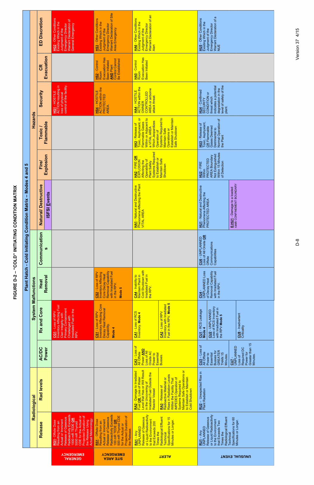
D
-8
Ver
sion
37
4/1
5
FIG
UR
E D
-2 –
“C
OL
D”
INIT
IAT
ING
CO
ND
ITIO
N M
AT
RIX
P
lan
t H
atch
- C
old
Init
iati
ng
Co
nd
itio
n M
atri
x –
Mo
des
4 a
nd
5
R
adio
log
ical
S
yste
m M
alfu
nct
ion
s H
azar
ds
Rel
ease
R
ad le
vels
A
C/D
C
Po
wer
R
x an
d C
ore
H
eat
Rem
ova
l C
om
mu
nic
atio
ns
Nat
ura
l/ D
est
ruct
ive
Fir
e/
Exp
losi
on
T
oxi
c /
Fla
mm
able
S
ecu
rity
C
R
Eva
cuat
ion
E
D D
iscr
etio
n
ISF
SI E
ven
ts
GENERAL EMERGENCY
RG
1-
Offs
ite D
ose
Res
ultin
g fr
om a
n A
ctua
l or
Imm
inen
t R
elea
se o
f Gas
eou
s R
adio
activ
ity E
xcee
ds
1000
mR
TE
DE
OR
50
00 m
R T
hyr
oid
C
DE
for
the
Act
ual o
r P
roje
cted
Dur
atio
n of
th
e R
elea
se U
sing
A
ctua
l Met
eoro
log
y.
CG
1 -
Loss
of R
PV
In
vent
ory
Aff
ectin
g F
uel
Cla
d In
tegr
ity w
ith
Prim
ary
Con
tain
men
t C
halle
nged
with
Ir
radi
ated
Fue
l in
the
RP
V.
H
G1
- H
OS
TIL
E
AC
TIO
N r
esul
ting
in
loss
of
phys
ical
co
ntro
l of t
he fa
cilit
y.
H
G2
- O
ther
Con
ditio
ns
Exi
stin
g W
hich
in t
he
Judg
men
t of t
he
Em
erge
ncy
Dire
ctor
W
arra
nt D
ecla
ratio
n of
G
ene
ral E
mer
genc
y
SITE AREA EMERGENCY
RS
1 - O
ffsi
te D
ose
Res
ultin
g fr
om a
n A
ctua
l or
Imm
inen
t R
elea
se o
f Gas
eou
s R
adio
activ
ity E
xcee
ds
100
mR
TE
DE
OR
50
0 m
R T
hyr
oid
CD
E
for
the
Act
ual o
r P
roje
cted
Dur
atio
n of
th
e R
elea
se.
CS
1 -
Loss
of R
PV
In
vent
ory
Aff
ectin
g C
ore
Dec
ay
He
at R
emov
al
Cap
abili
ty.
Mo
de
4
CS
2 -
Loss
of R
PV
In
vent
ory
Aff
ectin
g C
ore
Dec
ay
He
at
Rem
oval
Cap
abili
ty
with
Irr
adia
ted
Fue
l in
the
RP
V.
Mo
de
5
HS
4 –
HO
ST
ILE
A
CT
ION
with
in t
he
PR
OT
EC
TE
D
AR
EA
.
HS
2 -
Con
trol
R
oom
E
vacu
atio
n H
as
Bee
n In
itiat
ed
AN
D P
lant
C
ontr
ol C
anno
t B
e E
stab
lishe
d
HS
3 -
Oth
er C
ondi
tions
E
xist
ing
Whi
ch in
the
Ju
dgm
ent o
f the
E
mer
genc
y D
irect
or
War
rant
Dec
lara
tion
of S
ite
Are
a E
mer
gen
cy
ALERT
RA
1 -
An
y U
NP
LAN
NE
D
Rel
ease
of G
ase
ous
or L
iqui
d R
adio
act
ivity
to
the
Env
ironm
ent
th
at E
xcee
ds 2
00
Tim
es th
e R
adio
logi
cal E
fflue
nt
Tec
hnic
al
Spe
cific
atio
ns fo
r 15
M
inut
es o
r Lo
nger
.
RA
2 -
Dam
age
to Ir
radi
ated
F
uel O
R
Loss
of W
ater
Le
vel t
hat
Has
or
Will
Res
ult
in th
e U
ncov
erin
g of
Ir
radi
ated
Fue
l Out
side
the
Rea
ctor
Ves
sel
CA
3 -
Lo
ss o
f A
ll O
ffsi
te
Pow
er A
ND
L
oss
of
All
Ons
ite A
C
Pow
er to
E
sse
ntia
l B
uss
es.
CA
1 -
Los
s of
RC
S
Inve
ntor
y. M
od
e 4
CA
4 -
In
ab
ility
to
M
aint
ain
Pla
nt in
C
old
Shu
tdo
wn
with
Ir
radi
ated
Fue
l in
the
RP
V.
H
A1
- N
atu
ral a
nd
Des
truc
tive
Phe
nom
ena
Affe
ctin
g th
e P
lant
V
ITA
L A
RE
A
HA
2 -
FIR
E O
R
EX
PLO
SIO
N
Affe
ctin
g th
e O
pe
rab
ility
of
Pla
nt S
afet
y S
yste
ms
Req
uire
d to
Est
ablis
h or
M
aint
ain
Saf
e S
hutd
ow
n
HA
3 -
Rel
ease
of
Tox
ic, A
sph
yxia
nt,
or
Fla
mm
able
Gas
es
With
in o
r A
djac
ent t
o a
VIT
AL
AR
EA
W
hich
Jeo
pard
izes
O
pera
tion
of
Sys
tem
s R
equi
red
to
Mai
ntai
n S
afe
Ope
ratio
ns o
r E
stab
lish
or M
aint
ain
Saf
e S
hutd
ow
n
HA
4 - H
OS
TIL
E
AC
TIO
N w
ithin
the
O
WN
ER
C
ON
TR
OLL
ED
A
RE
A o
r ai
rbo
rne
atta
ck th
reat
.
HA
5 -
Con
trol
R
oom
E
vacu
atio
n H
as
Bee
n In
itiat
ed
HA
6 -
Oth
er
Con
ditio
ns
Exi
stin
g W
hich
in t
he
Judg
men
t of t
he
Em
erge
ncy
Dire
ctor
W
arra
nt D
ecla
ratio
n of
an
Ale
rt
RA
3 -
Rel
ease
of
Rad
ioac
tive
Mat
eria
l or
Ris
es in
Rad
iatio
n Le
vels
W
ithin
the
Fac
ility
Tha
t IM
PE
DE
S O
pera
tion
of
Sys
tem
s R
equi
red
to
Mai
ntai
n S
afe
Ope
ratio
ns o
r to
Est
ablis
h or
Mai
ntai
n C
old
Shu
tdo
wn
CA
2 -
Lo
ss o
f R
PV
In
vent
ory
with
Irra
diat
ed
Fue
l in
the
RP
V.
Mo
de
5
UNUSUAL EVENT
RU
1 –
An
y U
NP
LAN
NE
D
Rel
ease
of G
ase
ous
or L
iqui
d R
adio
act
ivity
to
the
Env
ironm
ent
th
at E
xcee
ds T
wo
Tim
es th
e R
adio
logi
cal E
fflue
nt
Tec
hnic
al
Spe
cific
atio
ns fo
r 60
M
inut
es o
r Lo
nger
.
RU
2 –
Un
exp
ecte
d R
ise
in
Pla
nt R
adia
tion
CU
3 –
Loss
of
All
Off
site
P
ower
to
Ess
en
tial
Bu
sse
s fo
r G
RE
AT
ER
T
HA
N 1
5 M
inut
es.
CU
1 -
RC
S L
eaka
ge
Mo
de
4
CU
4 -
UN
PLA
NN
ED
Lo
ss
of D
eca
y H
eat
Rem
oval
Cap
abili
ty
with
Irr
adia
ted
Fue
l in
the
RP
V.
CU
6 -
UN
PLA
NN
ED
L
oss
of
All
Ons
ite O
R
Offs
ite
Com
mun
icat
ions
C
apab
ilitie
s
HU
1 -
Nat
ural
an
d D
estr
uctiv
e P
heno
men
a A
ffect
ing
the
PR
OT
EC
TE
D A
RE
A
HU
2 -
FIR
E
With
in
PR
OT
EC
TE
D
AR
EA
Bou
ndar
y N
ot E
xtin
guis
hed
W
ithin
15
Min
utes
of
Det
ectio
n
HU
3 -
Rel
ease
of
Tox
ic, A
sph
yxia
nt,
OR
Fla
mm
able
G
ases
Dee
med
D
etrim
enta
l to
Nor
mal
Ope
ratio
n of
th
e P
lant
HU
4 -
Con
firm
ed
SE
CU
RIT
Y
CO
ND
ITIO
N o
r th
reat
whi
ch
indi
cate
s a
pote
ntia
l de
grad
atio
n in
the
leve
l of s
afet
y of
the
pl
ant.
H
U5
- O
the
r C
ondi
tions
E
xist
ing
Whi
ch in
the
Ju
dgm
ent o
f the
E
mer
genc
y D
irect
or
War
rant
Dec
lara
tion
of a
N
UE
CU
2 -
UN
PLA
NN
ED
Lo
ss o
f RC
S In
vent
ory
with
Irr
adia
ted
Fue
l in
the
RP
V M
od
e 5
CU
7 -
UN
PLA
NN
ED
Lo
ss o
f R
equi
red
DC
P
ower
for
Gre
ater
tha
n 15
M
inut
es.
E-H
U1
- D
amag
e to
a lo
aded
ca
sk C
ON
FIN
EM
EN
T B
OU
ND
AR
Y
CU
8 -
Inad
vert
ent
Crit
ical
ity

E-1 Version 37 4/15
E. NOTIFICATION METHODS AND PROCEDURES This section describes the plan for notification of onsite and offsite licensee emergency response personnel for HNP, State, local, and NRC emergency response centers. Actual methods and sequencing of notifications are covered in appropriate implementing procedures. Table E-1 presents the initial notification concept for normal working hours and backshift hours. Notification of HNP Personnel The ED is responsible for classifying an event (Section D) into the appropriate emergency class and ensuring onsite personnel are notified accordingly. This notification involves sounding the appropriate plant emergency alarm signal, making appropriate announcements over the plant public address (PA) system, and using the plant telephone system. The primary means for notification of personnel within the controlled area is the PA system. Upon declaration of an Emergency, personnel will be notified by a page announcement. For declaration of an Alert, a Site Area Emergency, or a General Emergency, this notification will be preceded by a warning tone. Likewise, page announcements for a Fire will be preceded by a specific tone. During security related events, the ED may elect to not sound a warning tone and, in such cases, will provide event specific instructions for onsite personnel over the PA system as well as other available communications means as needed. Notification of persons who are in the public access areas, on or passing through the site, or within the controlled area will be performed by the Security Department. All such notifications would be accomplished in accordance with the Emergency Plan implementing procedures. Visitors within the protected area are escorted by a permanently badged individual who is responsible for informing the visitors of emergencies when they occur and for taking action to evacuate the visitors from the site, as necessary. The ED is responsible for notifying the Hatch Duty Manager (who is on call 24 hours a day). This Duty Manager contacts Corporate. These notifications may be made utilizing available communications systems. Selected plant management can also be reached utilizing available communications systems. During normal working hours, emergency response personnel report to their assigned locations at the TSC and the OSC, as required by the specific emergency classification. Notification of EOF personnel will be accomplished utilizing available communications systems in accordance with Appendix 7. During backshift hours, the Operations SM is responsible for initiating the notification process to required emergency response personnel, directing them to report to their designated ERF. These notifications may be made utilizing available communications systems. Notification of State and Local Response Personnel The ED is responsible for ensuring that the State and local counties surrounding HNP are notified in a timely and accurate manner of an emergency condition. This notification consists of the information on the Emergency Notification Form (Figure E-1) being given within approximately 15 min of declaring an emergency to the following agencies: Georgia EMA.
The 24-hour warning points of Appling, Jeff Davis, Tattnall, and Toombs Counties.

E-2 Version 37 4/15
These agencies are responsible for notifying appropriate response personnel in accordance with their emergency plans and procedures. The ENN is a dedicated communications system that is normally used to accomplish these notifications. Commercial telephone, microwave, or land lines provide backup for the ENN. Figure E-1 presents the sample Emergency Notification Form for making notifications to these response centers. This form has been developed in conjunction with appropriate agencies. The Emergency Notification Form may be revised upon receipt of State and utility approval. Any revisions to the Notification Form are incorporated into the applicable implementing procedure are included in the next revision to the Emergency Plan. Verification of Notification Messages All ENN notification messages must be verified as being received by the State of Georgia and Appling, Jeff Davis, Tattnall, and Toombs Counties. Verification is normally accomplished by roll call. Notification of Federal Agencies The ED is responsible for ensuring notification calls are made to the NRC Operations Center by the ENS or commercial telephone as backup within the prescribed time constraints from the declaration of an emergency. A sample of the form used to provide the notification to the NRC Operations Center is shown in Figure E-2. Notification of the Public Administrative and physical means have been established for providing early notification and clear instruction to the populace within the plume exposure pathway EPZ. (See Appendix 3.) The prompt notification system has a capability to complete the initial notification within 15 min. The initial notification, when appropriate, of the affected population within the plume exposure pathway EPZ is to be completed by the State and/or local authorities in a manner consistent with assuring the public health and safety. The primary means for alerting and providing instructions to the public is by a siren system and Emergency Alert System (EAS). The prompt notification system (PNS) is described in Appendix 3. The licensee will provide offsite authorities with supporting information for their messages to the public. Such messages, consistent with the emergency classification scheme, will provide the public with instructions in regard to specific protective actions to be taken by occupants of affected areas.

E-3 Version 37 4/15
TABLE E-1
INITIAL NOTIFICATION SYSTEM NORMAL WORKING HOURS AND BACKSHIFT HOURS
Communicator
Primary Notification System
Party Notified
ED (or designated communicator)
PA system Protected area personnel (normal and backshift hours)
ED (or designated communicator)
Plant telephone system or PA system
Security Department personnel (normal and backshift hours)
Security Department Plant telephone system Visitors Center personnel
(normal working hours)
Visitors Center Director (backshift hours)
Security Department Direct contact Recreation area occupants
(normal and backshift hours) ED (or designated communicator)
Plant telephone system Off-shift personnel necessary for emergency response (backshift hours)
ED (or designated communicator)
ENN GEMA Communicator Appling County Communicator Jeff Davis County Communicator Tattnall County Communicator Toombs County Communicator (normal and backshift hours)
ED (or designated communicator)
ENS NRC Operations Center (normal and backshift hours)
ED (or designated communicator)
Plant telephone system (or commercial telephone)
Plant management Hatch Duty Manager (normal and backshift hours)
Hatch Duty Manager Plant telephone system
(or commercial telephone)
Corporate (normal and backshift hours)

Southern Nuclear Emergency Notification I§) ACTUAL E'JENT ·tBDR!LL
2.BINI~IAL NOCJFICATION: TIME. ____ DATE __ : __ .1 __ Al..miEN~ICATION# ~
3. SITE:: HATCH NUCLEAR pt AMI cmnrma:lon ll11ooe ~ (~12~ 3"·2000 ext __
4. EMERGENCY CLUIJRCATIOft:
D GENERAL EMERGENCY
BASED ONEAL~----- E"L DESC:ffiPTlON: ___________________ _
5. PROTECn'IE ACBON RECOMMEND~ liONS: IB~CUATE _______________________________________________________ __ ~SiiE:..i!'ER __________ ......._ _________________ _
§~StEFl "1>tE ;.;$OF l(l !POTol.SSIJII.i IO[ltre;! lSi Aet:Oi:i[lll;hOS 'lifT"' SlAT£ i'l.ANS:.4NO Pa..C'f. R~HER. ________________________________________________________________________________________ _
5 .. EMERGENCY RELEASE:
7. RELEASE SIGNIFICANCE:
B. E'JESTPROONOSIS:
'htmn normal cpefdn; llnls
gst:at:te
;A.bcr#e na:'!IHii cpeml:l!'i; ~
§ oegranlrg lh,na otrectklr from ---· c:egri!es \'llrrc Speed ___ mpn Predptan:m __ St:at:Ut)' Ciass~ E § § I§ fl 19
10. ~OECLA:V.TION jg{TERM!NATION Tlme ______ Date __ ! ____ ,. __
11. M=FECTEO UNITfS}: IIJ ~ ~ 8u1 ___ ,.Fcv."eJ" Srt...~.mnme _____ ca~ _,._· _,_. _ 12 .. UNIT s~;.. TUS:
(U~d U>'dl:s) atmus. t«t RequRd 'kr ~Si !I U;! ___ ,_ FCV.'el' !ih~ at"1me -----~ __ }_. _,._ Nom:alla!'IS)
1'3. REMARKS:: _________________________________ _
FOLLOW-UP INFORMATION tUnes 14 through 16 Not Reauired for Initial Notifications} EMERGENCY RELEASE DATA. NOT REQUfRED IF UNIE & A tS SELECTED.
14. FtELEASE CHA.RACTERIZ!\TION: MAGNJTUDE: Noble Gases:. ____ tcmnes: _____ Pift'Ucuta:.es:. ____ Otrer _____ _
FCRPil: !e) Alrb:Jme .start Time ____ Date -"--·~·_stop 'Tl!re ___ r:ate _,• __ ,•_
E L}qlltc:: Slart:Tirne DO'.:~ _,i_· _•_sq;, "1me ___ Date _: __ l_
15 .. PROJEC''1CN PA~4e:TERS: ~ec:tm pertcc:: ___ HeW'& ESI3rnated ~sea&e CUratJ..."r ___ roW'S
Profe:ti:ln pEf'fl:rnlH: Time Date _l _____ l_ .~ent Ty~: __ _
16. PROJEC~ED DOSE: DISTANCE
S!~b.."U.OO~"
2Mm5
5Mm5
HI Mlies
-----------------~~--------------NOTIFIED
Time Dale_,~_· -·'-
BY:----------1
RECEI'\I'ED BY:---------- Time .Date __ ,~ __ i __ .
~,.a~ CDfi'De~d tr1 re:et~no a~:
FIGURE E-1 (SHEET 1 OF 2) TYPICAL EXAMPLE OF EMERGENCY NOTIFICATION FORM
E-4 Version 37 4/15

E-5 Version 37 4/15
SOUTHERN NUCLEAR EMERGENCY NOTIFICATION
GOVERNMENT AGENCIES
Record the time(s) of contact with offsite authorities as indicated below: Record the time acknowledgement is
received prior to verbally transmitting ENN information
Record the time acknowledgement is received after completing verbal ENN
notification GEMA
(time) (time) Appling Co.
(time) (time) Jeff Davis Co.
(time) (time) Tattnall Co.
(time) (time) Toombs Co.
(time) (time)
FIGURE E-1 (SHEET 2 OF 2) TYPICAL EXAMPLE OF EMERGENCY NOTIFICATION FORM

GEORGIA POWER COMPANY PLANT E.l. HATCH PAGE 1 OF 4 FORM TITLE: CHECKliST FOR NOTIFICATION OF SiGNIFICANT EVENTS REPORT MADE IN ACCORDANCE W1TH 10CFR50.72, 10CFR73.71. 49 CFR. 10CFR20.403
I REACTOR PLANT EVENT NOTIFICATION WORKSHEET I EN#
NRC OPERATION TELEPHONE NUMBER: PRIMARY- 301-816-5100 or 8(]()..,532-3469", BACKUP'S- (1s1] 301-951-0550 orS00-449-3694~ [2ndl301-415-0550 and 13rdl301-415-0553 ~censees who maintain their own ETS are provided these telephone numbers.
NOTIFICATION TIME FACILITY OR ORGANIZATION I UNIT I NAME OF CAllER I CALLBACK#
EVENT TIME & ZONE EVENT DATE POWERMOOEBEFORE POWER MODE AFTER
EVENT ClASSIFICATIONS 1-Hr. Non-Emergency 10 CFR 50.72 Cb)(1) (V)(A) Safe S/0 Capability
GBEfW. EMERGENCY 1Hw' TS DEVIATION (V)(B) RHRC3pabil~
srrEAAEA EMERGENCY t lieu 4-Hr. Non-Emergency 10 CFR so.n Cb)(2) (V}(C) Control of Rad Release PLERT 11iru (i} TS Required SID NXD'i Accident Mitigation LlNUSUAL. EVENT tHw' (lv}(A) ECCS Discharge to RCS (Xli} Offsle Medical 5tt7l~GENCY ~ RPS Actuation (scram) (~iii) Loss CommiAsmiiResp PHYSICAL SS::I..Im'/ (73.7t} Offsite Notification 60-Day Optional10 CFR 50.73 (a)(1} IMTERIAIJEXPOSURE 8-Hr. Non-Ememencv 10 CFR 50.72 {b)(3. Invalid Scecified Svstem ActuaSian RTNESS FeR DUTY (ii)(A} Degraded COndition Other Unspecified Requirement (.Identify} OTHER I.JISPECIAED REQU[ (ii)(B) Unanalyzed Condilioo ~llONON..Y (iv)(A} Specified System Actuation
NRC OFFICIAl NOTIFIED: I NRC RESIDENT NOTIFIED
DESCRIPTION lndude: Systems affected, aduations and tfleir initiating signals. causes, effed ot event. on plant, actions taken or planned, etc. (Continue on back}
NOllRCATIONS YES NO WlllBE AN't'niiNG UNUSUAL OR D YES (Explain above} DNO NRC RESIDENT i= NOT UNDERSTOOD? STATE(s} DID .All SYSTEMS Dves D NO (Explain above~ LOCAL FUNCTION AS REQURED?
OTHER 001 AGENCIES MOOE Of OPERATIONS ESTIMATED ADDITIONAl INFO ON PAGES MEDIA/PRESS RELEASE UNTIL CORRECTED: RESTART: 2 & 3 (If NO do not attach)
YES DNO
FIGURE E-2 (SHEET 1 OF 4) TYPICAL EXAMPLE OF NRC OPERATIONS CENTER EVENT NOTIFICATION FORM
E-6 Version 37 4/15

GEORGIA POWER COMPANY PLANT E.l. HATCH PAGE 2 OF 4 FORM TITLE:
CHECKLIST FOR NOTIFICATION OF SIGNIFICANT EVENTS REPORT MADE IN ACCORDANCE WITH 10CFR50.72, 10CFR73.71, 49 CFR, 10CFR20
IF A RELEASE IS UNDERWAY, THEN PERFORM THIS ADDITIONAL INFORMATION PAGE, OTHERWISE DISREGARD.
Assign Operations personnel (or TSC personnel if the TSC is activated) to complete this checklist in accordance with the following instructions_ The Rad Monitor readings can be obtained from the control room instruments. Obtain radiological information (setprnnts,% Tech Spec, and readings) from Health Physics or Chemistry personnel as appropriate_ Notify Health Physics or Chemistry personnel of the type of release, if known, and they will obtain the appropriate information. References for completing pages 2 and 3 are located on page 4.
RADIOLOGICAL RELEASES: Check or fill in applicable items (specific details!explana1ions are to be covered in event description, page 1 ):
( ) LIQUID RELEASE ()ONGOING ( ) OFFSITE RELEASE" { ) PERSONNEL EXPOSED OR
CONTAMINATED
( ) GASEOUS RELEASE ( } TERMINATED ( ) T.S. EXCEEDED ( ) OFFSITE PROTECTIVE
ACTIONS RECOMMENDED
"STATE RELEASE PATH IN DESCRIPTION
( ) UNPLANNED RELEASE ( ) MONITORED ( )RM ALARMS
( ) PLANNED RELEASE ( ) UNMONITORED ( ) AREAS EVACUATED
RELEASE RATE % T_S_ LIMIT HOOGUIDE TOTAL ACTIVITY % T.S. LIMIT HOOGUID {Cilsec} (Ci)
NOBLE GAS 0.1 Ci/sec 1000Ci
IODINE 10 uCi/sec 0.01 Ci
PARTICULATE 1 uCifsec 1 mCi
LIQUID (EXCLUDING TRITIUM AND 10 uCilmin 0:1 Ci DISSOL VEO NOBLE GASES)
LIQUID (TRITIUM) 0.2Cilmin 5Ci
TOTAL ACTIVITY
PLANT STACK CONDENSER/AIR EJECTOR MAIN STEAM LINE OTHER
RAD MONITOR READINGS:
ALARM SETPOINTS:
% T.S. LIMIT (if applicable}
FIGURE E-2 (SHEET 2 OF 4) TYPICAL EXAMPLE OF NRC OPERATIONS CENTER EVENT NOTIFICATION FORM
E-7 Version 37 4/15

GEORGIA POWER COMPANY PLANT EJ. HATCH PAGE 3 OF 4 FORM TITLE:
CHECKLIST FOR NOTIFICATION OF SIGNIFICANT EVENTS REPORT MADE lN ACCORDANCE WITH 10CFR50.72, 10CFR73_71, 49 CFR, 10CFR20.403
REACTOR COOLANT SYSTEM LEAKS (CHECK OR FILL IN APPLICABLE ITEMS (SPECIFIC DETAILS/EXPLANATION TO BE COVERED IN EVENT DESCRIPTION):
LOCATION OF LEAK (e.g .. , valve, pipe, etc.):
LEAK RATE: UNITS: gpmlgpd T.S. LIMITS: SUDDEN OR LONG TERM DEVELOPMENT
LEAK START DATE: ___ TIME:. __ _ COOLANT ACTIVITY & UNITS: ( ) PRIMARY ( ) SECONDARY
LIST OF SAFETY RELATED EQUIPMENT NOT OPERATIONAL:
EVENT DESCRIPTION {continued from page 1)
FIGURE E-2 (SHEET 3 OF 4) TYPICAL EXAMPLE OF NRC OPERATIONS CENTER EVENT NOTIFICATION FORM
E-8 Version 37 4/15

GEORGIA POWER COMPANY PLANT E.l. HATCH PAGE 4 OF 4 FORM TITLE:
CHECKLIST FOR NOTIFICATION OF SIGNIFICANT EVENTS REPORT MADE IN ACCORDANCE WITH ·JOCFR50.72, 10CFR73.71, 49 CFR, 10CFR20.403
The following list consists of procedure numbers and instruments MPLs needed for completing pages 2 and 3. They are not listed in any order of priority for obtaining readings.
READING
NOBLE GAS: IODINE. PARTICULATE
lOCATION
64CH-RPT-007-0, Gaseous Effluents. Reports 64CI-OC~032-0, Kaman 64CI-OCB-001-0, Main Stack Radiation Monitoring 73EP-EIP-018-0, Prompt Offsite Dose Assessment 73EP-EIP-015-0, Offsite Dose Assessment
liQUID (EXCLUDING TRHIUM AND 64CH-RPT-006-0, Liquid Effluents Reports DISSOLVED NOBLE GASES): 64CH-SAM-024-0, Liquid RM' Sampling and Analyses
LIQUID {TRITIUM} (This is only available from offsite vendor)
PLANT STACKIRAD:
CONDENSER/AIR EJECTORIRAD:
MONITOR READlNGS:
ALARM SETPOINTS
MONITOR READINGS:
ALARM SETPOINTS
MAIN STEAM UNEIRAD: MONITOR READINGS:
ALARM SETPOINTS
COOLANT ACTIVITY & UNITS: PRIMARY SECONDARY
lEAK RATE:
%Tech Spec:
AlARM SETPOINTS:
HOO Guide (Headquarters Operation Officer):
64CI-OCB-OO·t-O, Main Stack Radiation Monitoring SPOS Midas Screen
1011-K600, Main Stack (CPS) (1H11-P604) 1D11-R631, Main Stack Kaman (uCi/cc) {1H11-P689}
Chemistry Setpoint Log
'112D11-K601/112D11-K602 (112H11-P604), 1/2011-R601 l t12D11-R602 ('1/2H'11-P600) 64CI-OCB-006-0, Pretreatment Radiation Monitors
Chemistry Setpoint Log
112011-K603A-D {1/2H11-P606), 1120 ·11-R603 ·(2H 1·1-PGOO) 64CI-OCB-007-0, Main Steam Line Rad Monitors
Chemistry Setpoint Log
64CH-SAM-025-0, Reactor Coolant Sampling 64CH-SAM-021-0, Pass, Post Accident 64CH-SAM-020-0, Pass, Normal
34SV-SUV-019-1/2, if Drywellleakage.
This limit can be acquired from HP/C personnel when contacted for rad reading. The limits are listed in the ODCM.
The HP/C Department maintains a setpoint log and these numbers can be acquired from the HP!C personnel when contacted.
This is a setpoint used by the NRC to trigger further actions by them and is not used by the utility.
FIGURE E-2 (SHEET 4 OF 4) TYPICAL EXAMPLE OF NRC OPERATIONS CENTER EVENT NOTIFICATION FORM
E-9 Version 37 4/15
F-1 Version 37 4/15
F. EMERGENCY COMMUNICATIONS This section describes the provisions for communications among the principal response organizations and among the licensee ERF. Communications with the State of Georgia The primary means of communication between the HNP and the State of Georgia is the ENN, which is a dedicated communications system from the plant to the EOC at GEMA headquarters in Atlanta, Georgia and the FEOC in Vidalia, Georgia. Extensions for this system are located in the Control Room, the TSC, and the EOF. The ENN system is available and manned 24 hours per day. The ENN provides the licensee the capability to notify State and local authorities of an emergency within 15 min. of declaration. Commercial telephones, microwave, or land lines provide backup for the ENN. Communication with contiguous local governments in the Ingestion Planning Zone (IPZ) will be coordinated through the State of Georgia. Communications with Plume Exposure Pathway EPZ Counties The primary means of communication between HNP and each EPZ county is the ENN, which is a dedicated communications system from the plant to each county EOC and 24-hour point of contact. Commercial telephones, microwave or land lines discussed above provide backups for the ENN. Radio contact between the plant and the Appling County Sheriff's Office can also be established, if necessary. The ENN is available and manned 24 hours per day. At the plant, the ED is responsible for ensuring contact with each of the plume exposure pathway EPZ counties. Communications with NRC and Other Federal Agencies The primary means of communication between HNP and the NRC is the ENS, a dedicated communications system from the plant to the NRC Operations Center. The NRC Region II office in Atlanta, Georgia, may also be connected to the ENS through the NRC Operations Center. Additional dedicated telephone circuits [known as the Federal Telecommunications System (FTS)] are installed in the TSC and the EOF. The Emergency Response Data System (ERDS), which provides specific plant parameters to the NRC via internet connection, is installed in the Computer Room and the TSC. Commercial telephone lines and the microwave system serve as backups to the ENS. Communications with other Federal emergency response organizations would be by telephone; such communications would normally be completed by GEMA from the State EOC.

F-2 Version 37 4/15
Communications Among HNP ERF Communications among the Control Room, the TSC, the OSC, and the EOF can be completed using various communications systems including dedicated telephone circuits, normal plant telephones, and radios. A radio system is also used for communications with the radiological monitoring teams. Communications available at each ERF are as follows: 1. Control Room
• Dedicated Voice Over Interrnet Protocol (VOIP) phones to the TSC, the OSC, and the EOF.
• One extension to the ENN.
• One extension to the NRC ENS.
• ERDS to the NRC.
• Normal plant phones (network or commercial).
• Base station radio console (multiple frequencies).
• Sound-powered phones (internal to Control Room only).
• Plant PA system.
• One facsimile line.
TSC
• Dedicated Voice Over Internet Protocol (VOIP) phones to the Control Room, the OSC, and the EOF.
• One extension to the ENN.
• One extension to the NRC ENS.
• ERDS to the NRC.
• One facsimile line.
• Normal plant phones (network or commercial).
• Base station radio console (multiple frequencies).
• Plant PA system.
OSC
• Dedicated Voice Over Internet Protocol (VOIP) phones to the Control Room, the TSC, and the EOF.

F-3 Version 37 4/15
• Normal plant phones (network or commercial).
• Base station radio console.
• Plant PA system.
EOF
• Dedicated Voice Over Internet Protocol (VOIP) phones to the Control Room, the TSC, and the OSC.
• One extension to the ENN.
• An extension to the NRC ENS.
• Multiple facsimile lines.
• Normal phones (network or commercial).
• Southern LINC radio equipment.
Medical Support Facility Communications Communication between HNP and the Appling General Hospital or the Meadows Regional Medical Center is by commercial telephone. The Appling Ambulance Service and the Meadows Regional Medical Center Ambulance Service are equipped with radio for communications with the hospitals. Normally, ambulance services and hospitals within the State are interconnected in a statewide hospital radio network. Alerting Emergency Response Personnel As described in Section E, notification of onsite personnel at HNP is completed utilizing available communications systems. HNP personnel not onsite at the time of the emergency are also notified utilizing available communications systems. Communications System Tests Communication channels with the State of Georgia, the plume exposure pathway EPZ counties, and the NRC (with the exception of ERDS) are tested each calendar month, using the extensions in the Control Room, the TSC, and the EOF. ERDS is tested each calendar quarter. All communications procedures and systems are also tested each calendar year during a communications drill. This drill is normally conducted in an exercise each calendar year.
G-1 Version 37 4/15
G. PUBLIC EDUCATION AND INFORMATION The detailed planning for public information actions during an emergency, including rumor control, is contained in the GPC HNP Emergency Communication Plan. A general description of the public education and information program follows. Each calendar year, information is provided to the public regarding how they will be notified and what their actions should be in an emergency. The means for disseminating this information includes, but is not limited to, information in local telephone books, posting in public areas, and/or publications distributed by mail. Each calendar year, information is distributed to residents in the plume exposure pathway EPZ through various publications. Information includes the following: • Instructions in response to the SNC siren system including the annual audible test.
• How the emergency notification will take place.
• Discussions of protective measures such as sheltering and evacuation and actions to take in either case.
• Radio stations where additional information will be broadcast.
• Evacuation routes and reception centers including a map and instructions.
• Educational information on radiation.
• Special needs and considerations for the handicapped.
• Contacts to obtain additional information.
A Visitors Center is operated onsite. The center is staffed with public information personnel who provide public education programs to the community and any other visitors. These programs typically focus on plant operational concepts, plant safety considerations, and radiation. Information for Transients Posted "Emergency Information" signs and a notice published in the local telephone books are used to provide the transient population with appropriate emergency information and instructions. The information/instructions advise the public on how they will be notified in the event of an emergency; indicate the actions to take if notified; and refer the public to designated broadcast stations for information in the event of a serious emergency. Method of Emergency Information Dissemination Any proposed change in the method of dissemination of emergency information to the public must be coordinated and discussed with, and agreed upon by appropriate State and local offsite emergency officials prior to implementation of the change. The Emergency Plan may be changed with regard to the manner in which the information is provided to the public under 10 CFR 50.54 (q) provided the requisite emergency information remains the same as currently

G-2 Version 37 4/15
approved by the NRC and FEMA as contained in the Hatch Emergency Plan and the FEMA-43 Report for the Edwin I. Hatch Nuclear Plant. Joint Information Center (JIC) Operations The JIC is the point of contact with the news media during an emergency. The JIC facilities used to coordinate the dissemination of information to the media will be established to accommodate public information representatives from the licensee, Federal, State, and local response agencies. News releases and media briefings are coordinated to the maximum extent possible. The licensee utilizes the GPC Corporate Headquarters Building located in Atlanta, Georgia, to serve as a temporary information center until the JIC located next to the GPC Operating Headquarters in Vidalia can be activated. The JIC is located approximately 22 miles from the plant and is large enough to accommodate a large number of reporters. Once activated, the JIC becomes the principal location for the dissemination of information relative to the emergency. News media who may arrive at the plant site during a declared emergency will be directed to the Joint Information Center to obtain approved news release information. The principal licensee contacts for the media are the Public Information Director and the designated Company Spokesperson. The Company Spokesperson has access to the ED through the EOF Manager. The Company Spokesperson briefs the media on plant status and company emergency activities. In addition, technical briefers who can provide general and background information, as appropriate, to reporters at the JIC have been designated. Further information relative to the public information organization and information flow to the public during an emergency is available in the HNP Emergency Communications Plan. Offsite Agency Coordination Timely and accurate information is provided to Federal, State, and local agencies. The licensee seeks reciprocal information from these agencies. Efforts are made to coordinate periodic press briefings and to issue public statements in conjunction with these government agencies. A joint public information center operation at the JIC provides ample opportunity for all parties represented to review all information prior to public release. Rumor Control Providing timely, accurate, and consistent information to the public is considered the most effective method of dispelling rumors. Rumors are controlled by having a single source of information. In an emergency, a rumor control network is activated. News media are monitored to detect and respond to misinformation. Offsite information is the responsibility of offsite agencies; however, rumor control is coordinated between the State and licensee. Media Education Information is provided and a program is offered each calendar year to acquaint the news media with the methodology for obtaining information during an emergency and background about overall EP at HNP. Included is information about the plant, radiation and the role of the JIC.
H-1 Version 37 4/15
H. EMERGENCY FACILITIES AND EQUIPMENT Following the declaration of an emergency, response activities will be coordinated at a number of facilities. These facilities and the equipment which will be used for assessment and monitoring functions are described in this section. Emergency Facilities 1. TSC
The TSC, which is shared by both units, is located adjacent to the service building annex. The layout of the TSC is shown in Figure H-1. Walking time from the TSC to the Control Room is approximately 2 min. The TSC covers approximately 2620 ft2. The TSC provides plant management and technical support personnel [including five NRC personnel] with adequate space to assist plant operating personnel located in the Control Room during an emergency. The TSC is equipped with technical data displays and has ready access to plant records to allow TSC personnel to perform detailed analysis and diagnosis of abnormal plant conditions, including assessment of any release of radioactivity to the environment. The TSC structure and ventilation system are designed to ensure that TSC personnel are protected from radiological hazards similar to that of the Control Room. An ARM which alarms on abnormal radiation levels is provided in the TSC. In addition, portable radiation monitors are available for personnel in transit from the TSC to other areas. Self-contained breathing apparatus (SCBA) are provided in the TSC. Anticontamination clothing is available at the nearby OSC. The TSC normal lighting is supplied from normal site power through a motor control center backed up by the security DG. Power for the TSC vital equipment is provided from either the motor control center backed up by the security DG or from a battery-backed uninterruptible power supply system. Power to the dc system is provided via battery chargers, one of which is powered from this same motor control center. The TSC records area maintains copies of the following documents:
• TS.
• Plant Operating Procedures.
• EOP.
• Final Safety Analysis Reports (FSARs).
• System piping and instrumentation diagrams and heating, ventilation, and air-conditioning (HVAC) flow diagrams.
• Piping area drawings.

H-2 Version 37 4/15
• Electrical one-line, elementary, and wiring diagrams.
• Control logic and loop diagrams.
• Emergency Plan and implementing procedures.
The above records are available in current form and are updated, as necessary, to ensure the content is accurate and complete. In the event the TSC becomes uninhabitable during an emergency, the Control Room will serve as an alternate location for TSC management. Operations at the TSC are directed by the TSC Manager.
OSC
The OSC consists of the service building breakroom and other areas, as necessary, to stage support personnel. This includes groups such as Instrument Technicians, Mechanics, Electricians, Nuclear Chemistry and HP Technicians, System Operators, and oncoming shift personnel who assemble to aid in the response to an emergency. In addition, the OSC is the initial assembly point for all radiological emergency team (RET) members. Briefings will be held with each team prior to being dispatched. Work to be performed, cautions, plant conditions, and radiological information will be included in the briefings. Status boards containing plant conditions and emergency classification will be available in the OSC. The layout of the OSC is shown in Figure H-2. Emergency kits containing radiation monitoring equipment, first-aid supplies, decontamination supplies, breathing apparatus, portable lighting, and hand-held radios are available to the OSC. Typical emergency kit contents are listed in Appendix 4. In the event the OSC becomes uninhabitable during an emergency, OSC functions will be conducted from the alternate OSC located in the Simulator Building. Operations at the OSC are directed by the OSC Manager.
EOF
Description of EOF operations and staffing is contained in Appendix 7.
Simulator Building
This location consists of several rooms, as shown in Figure H-3. These rooms are normally used as classrooms and training labs. Designated rooms are utilized for equipment storage. Available classrooms and conference rooms will be utilized for field monitoring team assembly and dispatch activities and for the alternate OSC. This area of the Simulator Building has a ventilation system that is functionally similar to the system used in the TSC without charcoal filtration. During normal mode of operation, a slight positive pressure is maintained. During emergency operation, no outside air is allowed and positive pressure is not maintained. The ventilation system has recirculation through high-efficiency particulate air filters during emergency mode only. This location is

H-3 Version 37 4/15
designed to provide a radiation protection shielding factor of 5. Dedicated portable radiation monitors are available for surveillance. Normal power to the simulator building is from offsite power. Emergency lighting is provided by 3-hour wall packs. Kits containing equipment for conducting offsite radiological monitoring are located in the Simulator Building on plant site. Typical contents of these kits are listed in Appendix 4.
Alternative Facility During a security related event or other event that precludes onsite access, the TSC and OSC ERO staff will be directed to an alternative facility. This facility is located in the Plant Hatch JIC building across the hall from the Public Information Workroom and adjacent to the Public Response Workroom. The alternative facility is equipped with the necessary communications and data links to support communications with the control room, site security, and the EOF. The available communications and data links also provide access to SNC document management resources and work planning resources for performing engineering assessment activities, including damage control team planning and preparation for return to the site. Joint Information Center (JIC) Description of the JIC resides in the HNP Emergency Communications Plan. Activation and Staffing of Emergency Facilities During the initial stages of an emergency, activities at HNP are directed from the Control Room. For a NUE, no other facilities are activated. Upon declaration of an Alert or higher level classification, the TSC is activated and becomes fully operational ASAP, but not later than approximately 1 hour following the initial notification. Overall direction and control are exercised from the TSC for an Alert or Higher situation. The ED may establish himself either at the Control Room or TSC, generally from the TSC. Activation of the OSC is initiated at an Alert or higher level classification. Support personnel are directed to report to that facility, as appropriate, for the specific situation. The OSC becomes operational ASAP, but not later than approximately 1 hour following initial notification. Activation and staffing of the EOF is contained in Appendix 7. For security related events, the activation of emergency facilities may be delayed as described in section B. Activation of ERO members will be performed for hostile action based events to promptly staff alternative facilities, in order to minimize delays in overall site response. The ERO will be staged in a manner that supports rapid response to limit or mitigate site damage or the potential for an offsite radiological release.

H-4 Version 37 4/15
Plant Monitoring and Data Handling Systems 1. Geophysical Phenomena Monitors
a. Meteorological
Meteorological monitoring is in place at HNP. The instruments are mounted on a 100-meter primary tower located to the south of the power block and on a 45-meter backup tower located to the southeast of the power block. Parameters measured and transmitted to the Control Room include: • Windspeed.
• Wind direction.
• Vertical temperature difference.
• Ambient temperature.
A building that houses meteorological equipment is located near the base of each tower. The system is powered by an uninterruptible power supply for high availability. Additionally, meteorological information can be obtained from the National Weather Service to supplement onsite data and provide a backup to the plant meteorological monitoring program on an as-needed basis. The important parameters for characterizing the transport of airborne radioactivity are windspeed, wind direction, and atmospheric stability (e.g., derived from the standard deviation of the horizontal wind direction or vertical temperature difference). These meteorological parameters are used in a calculational methodology to assess the offsite radiological consequences of accidental releases of airborne radioactivity. The methodology is described in Section I, Accident Assessment.
b. Hydrologic
The normal and emergency source of plant cooling water is the Altamaha River, which provides makeup to the cooling towers. The probable maximum flood level is approximately 105 ft msl.
c. Seismic
Seismic monitoring instrumentation for HNP consists of time-history accelerographs, peak recording accelerographs (PRAs), a response-spectrum recorder, and seismic switches. One triaxial seismic switch, with a horizontal setpoint of 0.08 g, is installed on the drywell pedestal on the 87 ft level of the Unit 2 reactor building. A second seismic switch is located outside the biological shield on the 185 ft level of the Unit 2 reactor building and has a vertical setpoint of 0.063 g. They are backup devices which actuate visual and audible annunciators in the Control Room.

H-5 Version 37 4/15
Activation of the seismic switches causes an audible and visual annunciation in the Control Room to alert the plant operator (PO) that an earthquake has occurred. These initial setpoints are based upon experience in existing plants and may be changed once significant plant operating data, which indicate that a different setpoint will provide better strong-motion accelerometer (SMA) system operation, are obtained.
d. Fire Detection
The fire detection system at HNP includes smoke and thermal detectors and manual fire alarms. Fire detection systems are provided in all areas with safe shutdown equipment, as well as other locations throughout the plant. In addition to initiating fire suppression systems, indications from the fire detection system are transmitted to the Control Room.
Radiation Monitoring System (RMS)
The RMS receives and processes radiological input readings during normal and abnormal operating and accident conditions; measures, evaluates, and reports radioactivity in designated areas; and monitors releases of radioactive materials in liquid and gaseous effluents. Data from the RMS are available in the Control Room. A more detailed description of the RMS is provided in the HNP-2-FSAR, Section 11.4. There are three types of radiation monitors in the RMS: airborne and air particulate radiation monitors, liquid radiation monitors, and post-accident radiation monitors. The post-accident radiation monitors provide radiation monitoring after an accident. The monitors are comprised of area, airborne, and air particulate monitors. Area monitors respond to gamma radiation photons within any energy range from 60 KeV to 3 MeV. Airborne monitors are capable of detecting and measuring radioactive gaseous effluent concentrations with compositions ranging from fresh equilibrium noble gas fission product mixtures to 10-day-old mixtures. Backup power to the post-accident monitors is supplied by a DG to ensure against interruption of monitor operation and loss of data.
SPDS
The SPDS provides a display of plant parameters from which the status of operation can be assessed, in the Control Room, the TSC, and the EOF. The SPDS performs the following functions:
• Aids Control Room operators in the rapid detection and identification of abnormal operating conditions.
• Provides additional specific information used to analyze and diagnose the cause of abnormal operating conditions.
• Monitors plant response to corrective actions.
• Provides grouping of parameters to enhance the operators' capability to quickly assess plant status without surveying concurrently all Control Room displays.

H-6 Version 37 4/15
• Directs the operators' attention to other specific confirmatory non-SPDS Control Room displays.
• Provides human factors engineered display formats in simple and consistent display patterns and codings.
• Provides display information on a real-time basis, along with validation of data.
• Provides generated selectable trend displays on a real-time basis for monitoring reactivity control, reactor core cooling and heat removal from the primary system, RCS integrity, radioactivity control, containment integrity, and other selected parameters.
The SPDS in the Control Room consists of displays of sets of concentrated parameters from which plant safety status can be rapidly assessed. SPDS can also be displayed in the TSC and the EOF to maximize the exchange of information between these facilities and the Control Room. The SPDS is in operation during normal and abnormal operating conditions. The selection of parameters to be displayed on the SPDS is based on the parameters required to monitor the critical safety functions identified by the General Electric Owners Group (GEOG). These parameters will aid Control Room operators in determining the safety status of the plant. The justification for selecting these parameters is contained in the analyses and background information generated by the GEOG to support the critical safety function restoration guidelines. The emergency response guidelines, which contain the critical safety function restoration guidelines and identify the parameters used to monitor the critical safety functions, have been submitted to the NRC by the GEOG.
Post-accident Sampling Capability
Capability exists for obtaining grab samples of reactor coolant samples (RCS), suppression pool coolant samples, and primary containment atmosphere samples. Various chemical analyses and radiological measurements on these samples can be performed, including the determination of radionuclide concentrations. Analysis may be performed onsite if radiological conditions allow; otherwise, analysis will be performed at an offsite laboratory facility. The results from these analyses are used to assess the extent of core damage and the potential source term.
Laboratory Facilities
HNP has a laboratory facility for analysis of radioactive samples. The major pieces of equipment include a solid-state gamma spectrometer and a beta/gamma gas proportional counter. The training section of the simulator building includes a laboratory which can be used for analysis of environmental media. Analysis instrumentation suitable for analyzing environmental samples is available at that location. Backup laboratory facilities are available at Plant Vogtle. This backup capability would be used if facilities at HNP were not available. Additionally, arrangements have been made for commercial offsite laboratory analysis, as needed.

H-7 Version 37 4/15
Other Process Parameters
Several other process parameters, including RCS pressure and temperature, containment pressure and temperature, liquid levels and other system indications, are useful both for the initiation phase and continued assessment. Several of these are used in the classification process as discussed in Section D, Emergency Classification System.
Offsite Radiological Monitoring
HNP has sufficient portable equipment and trained personnel to field a minimum of three field monitoring teams. These teams are dispatched to offsite locations and are also utilized for site boundary and owner-controlled area surveys. Each team obtains emergency monitoring materials and equipment including dosimetry, two-way radio equipment, meters for measuring gamma and beta/gamma dose rates, and air samplers for collecting particulates and iodines.
Emergency Supplies and Equipment
Emergency supplies and equipment are located in the Control Room, the TSC, the OSC, and the Simulator Building. Procedures require an inspection and operational check of equipment in these kits on a quarterly basis and after each use. Equipment in these locations is calibrated in accordance with existing plant procedures. Spare equipment is also maintained to replace inoperative or out-of-calibration equipment. Typical listings of the emergency supplies and equipment are included in Appendix 4.

H
-8
Ver
sion
37
4/1
5
FIG
UR
E H
-1 -
T
SC
TY
PIC
AL
LA
YO
UT
PL
AN
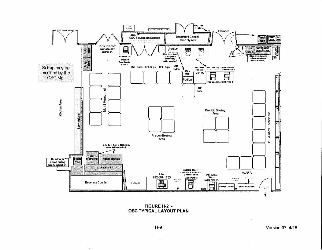
Set up may be modified by the
OSCMgr
c Q) ..c (J ~
::s:::
CUJ:J~a't COOrdlnata
1): J~i'l
D 10 >----<Q)
-,...,......~_,~0 DO
p~~ toe~ l"'rjlf b lis IIX.:slm 4u-I"Q1Icllt;.:sciMIIICII'Il
Pre-Job Bri e1ing .Ate a
Fax 912-::67-1135
[!!]
FIGURE H-2 -
~ ..... ' " 080 Mg r. OOC: MllrL OG T +am Tr.IOkln G
li.Golr.tant oommu nloaU. r
HP Sup..o.
~'EBEJC ll q~ola;• oo mpu ~r i.. pro jto1o n
f.'JG'ilm oon1ToiG •v'll::HIP00::4->
Pre-Job Briefing fttea
D
D ITIJ
ALAR A
OSC TYPICAL LAYOUT PLAN
H-9
(;) c on ·c 'E ..c (J Q) I-
~ ..c u «< a. :r:
Version 37 4/15

H
-10
Ver
sion
37
4/1
5
FIG
UR
E H
-3 -
S
IMU
LA
TO
R B
UIL
DIN
G T
YP
ICA
L L
AY
OU
T P
LA
N

I-1 Version 37 4/15
I. ACCIDENT ASSESSMENT This section describes the methods, systems, and equipment available for assessing and monitoring actual or potential offsite consequences of a radiological emergency. Initial assessment actions are the responsibility of the Operations SOS and/or the SS, using available shift personnel. Subsequent assessment actions are directed by the ED with assistance from the Control Room, TSC, the EOF, and the emergency teams, as necessary. Plant Parameters Plant system and effluent parameter values characteristic of the spectrum of off-normal conditions and accidents and the manner in which these values are used to classify an emergency are provided in Section D. Some of the parameters monitored include: RCS pressure, reactor water level, drywell pressure, drywell radiation level, effluent monitor readings, and ARM readings. Emergency response procedures include methods for quickly assessing plant system and effluent parameter values and classifying the emergency condition. Additional information relative to plant instrumentation is provided in Section H. Radiological Monitors In-plant radiological measurements provide information helpful in assessing emergency conditions. Systems are installed to permit reactor coolant and drywell atmosphere sampling under emergency conditions. Post-accident sampling capability and the RMS are described in Section H of this Plan. The drywell wide-range radiation monitor and the drywell hydrogen monitor are used to provide an early indication of the quantity of radioactivity available for release from the containment. Plant procedures include a correlation between the monitor reading and the extent of core damage. Estimates derived from these monitor readings are used until a sample using PASS has been obtained and analyzed. Determination of Release Rate Section H of this Plan describes RMS and PASS. These systems, in combination with procedures located in the Control Room, the TSC, and the EOF can provide the information needed to determine the radiological source term. Emergency response procedures provide methods for determining relationships between monitor readings and releases and/or material available for release. Dose Projection System The Meteorological Information Dose Assessment System (MIDAS) is the dose calculation computer model used at HNP. Dispersion is computed using either a straight line or the variable trajectory dispersion model. Both models are time-dependent and provide integrated doses, as well as dose rates, using EPA 400 dose factors. The dose calculation model will be provided in the Control Room, TSC, and EOF for use in projecting potential offsite doses. The TSC will assume responsibility for this function from the Control Room after the TSC is activated. This function will be transferred to the EOF as soon as practicable from the TSC, to relieve the TSC of unnecessary burden; however, the TSC will

I-2 Version 37 4/15
maintain the capability of dose projections should the EOF not be available. Backup calculations will be performed in the TSC, as needed. Meteorological data are obtained and evaluated, as described in Section H. The meteorological data collection system can be accessed directly from the Control Room, the TSC, and the EOF. The EOF will be able to provide this information upon request to any offsite organization. Field Monitoring Up to three teams will be deployed for field monitoring. These teams are available for offsite field monitoring within the plume exposure pathway EPZ, as described in Section H. Initially at least two persons can be dispatched from on-shift personnel for offsite surveys. The on-shift HP/Chem department foreman will provide for field monitoring coordination until the TSC is activated. Once the emergency facilities are activated, the HP/Chem Supervisor in the TSC or the Dose Assessment Supervisor in the EOF can request monitoring teams from support personnel located at the OSC. Field Monitoring Teams consist of at least two people. These teams are formed at the OSC and dispatched as described in Section B. Materials and equipment for conducting offsite radiological monitoring are located in the Simulator Building. Typical equipment available for field monitoring is listed in Appendix 4. Offsite field monitoring teams normally use company vehicles and have a two-way radio for communications. It is estimated that teams can be in the field and performing monitoring tasks within approximately 1 hour of the determination of the need for field monitoring. Preselected radiological sampling and monitoring locations are designated on the HNP 10-mile EPZ field monitoring map. Offsite field monitoring teams perform sampling at these locations and others as directed by the HP/Chem Supervisor in the TSC or the Dose Assessment Supervisor in the EOF. A communicator maintains periodic communications contact with all field monitoring teams. To facilitate direction of the teams and reporting of results, both the field monitoring teams and the communicator use identical maps showing the sampling locations. The emergency monitoring kits contain a portable air sampler and appropriate cartridges (silver zeolite) and counters to provide the capability to detect and measure radioiodine concentrations in air as low as 10-7 µCi/cc. The cartridges can be counted in the field without interference from noble gas (background count rate below 300 cpm on an HP-210 probe or equivalent). The cartridge and air particulate filter are returned to the laboratory at the plant site for isotopic analysis if the field analysis reading is 100 cpm above background on an HP-210 probe or equivalent. In addition to direct monitoring and air sampling, the assessment program may utilize the environmental sampling program in which environmental samples (water, air, soil, and vegetation) are collected and analyzed in the laboratory for detailed radionuclide data. This program is implemented at the direction of the Dose Assessment Manager or designee. Data obtained from the field monitoring program (including data from offsite agencies) can be utilized to perform or refine dose projections. Any adjustments to dose projections will be considered in the evaluation of protective action recommendations as described in Section J.
J-1 Version 37 4/15
J. PROTECTIVE RESPONSE This section describes the protective actions that were developed to limit radiation exposure of plant personnel and the public following an accident at the plant. This section addresses conditions relative to the Alert, the Site Area Emergency, or the General Emergency classifications. Any protective response taken at the NUE level is done so at the discretion of the ED. Protective Response for Onsite Personnel Protective response for onsite personnel (including visitors and contractor personnel) depends upon alerting, assembly and accountability, evacuation, monitoring, and decontamination. 1. Alerting
Section E of this Plan, Notification Methods and Procedures, describes the methods to be used to alert onsite personnel of emergency conditions.
Assembly and Accountability
Upon activation of the plant emergency alarm, plant personnel assigned specific emergency responsibilities proceed to their designated respective emergency response locations, where they are logged in and accounted for. Accountability reports for the Control Room, the OSC, and the TSC are provided by the Security Department ASAP. Thereafter, personnel emergency assignment tracking will be in place at each of the ERF to account for all onsite individuals throughout the emergency. This accountability may include use of the security computer system, assignment logs, and required periodic communications between emergency teams and the Control Room and the TSC. Nonessential plant personnel report to their normal reporting area during an Alert for the purpose of assembly and initial accountability. Visitors, contractors, and escorted personnel will leave the protected area during an Alert or higher declaration. Nonessential plant personnel located within the protected area leave upon hearing the Site Area or the General Emergency alarm. The Security Department accounts for each person inside the protected area by using the security computer system, which is provided Emergency Diesel backup power as well as an emergency backup fail-over computer. This system is supplemented by the availability of telephone and radio communications capability between the Control Room, the OSC and the TSC. This methodology provides for accountability of all individuals inside the protected area within approximately 30 minutes of the emergency declaration. Accountability reports are made periodically to the ED by the Security Department. Nonessential plant personnel, visitors, and contractors located within the protected area proceed to a rally point location outside the protected area [normally, the Plant Entry Security Building (PESB); however, if radiological conditions prohibit its use, Gate 17 or any ED designated gate exiting the protected area may be used as a rally point]. A security patrol periodically inspects all offices and work locations outside the protected area to ensure that all personnel have received instructions regarding onsite protective measures.

J-2 Version 37 4/15
Search and Rescue
If protected area accountability reveals a missing person, the ED or designee assembles a search and rescue team per the emergency response procedures. The search and rescue team can obtain information on last known location from the security computer system or reports from other personnel. A search of likely areas will be conducted until the missing individual is located.
Evacuation
Evacuation of all nonessential personnel (if feasible) is ordered by the ED whenever: a. It is determined that a threat to the safety of onsite personnel exists.
b. A Site Area Emergency or a General Emergency is declared.
The ED or designee provides evacuation route directions to personnel directed to leave the plant site using the PA system and other communications means. This information, including the evacuation routes (North and/or South on U.S. Highway 1) are included in applicable implementing procedures. Nonessential plant personnel, visitors, and contractors will be directed to the designated county relocation centers if a radiological release is in progress during the emergency. The appropriate relocation centers are Toombs County High School for northern evacuations and Appling County High School for southern evacuations. Evacuation is generally by individually owned vehicles. Directions provided to evacuees are based on radiological necessities and specific protective action requirements.
Security Events
Onsite protection of employees during hostile actions involves a combination of restricted movement, movement to safe locations, and site evacuation depending on the nature of the hostile event and advance warning. Site procedures provide specific actions to take during hostile action based events. These actions will be communicated to onsite personnel via the plant PA system and other communications means as applicable.
Monitoring and Decontamination
When an Alert is declared but no site evacuation is anticipated, personnel who have left the protected area are monitored by portal monitors. If necessary, decontamination is completed using the plant decontamination facilities located in the Control building or other onsite locations. For a Site Area Emergency or a General Emergency, or when site evacuation is expected and a release of radioactivity has occurred, monitoring is performed by portal monitors at the PESB or by portable monitoring equipment at the rally point areas. The Rally Point Team establishes a control point at the rally point area and monitors evacuees before releasing them. The monitoring teams maintain the appropriate records. Should decontamination become necessary, the Rally Point Team will conduct decontamination onsite, preferably at the predesignated locations in the Environmental

J-3 Version 37 4/15
Building or Building 10. Decontamination and waste disposal are completed in accordance with plant procedures.
Use of Onsite Protective Equipment and Supplies
Plant emergency kits and other supplies are used to provide dosimetry, monitoring equipment, protective clothing, and respiratory protection gear for individuals arriving or remaining onsite during the emergency. A supply of potassium iodide is stored in the primary ERF and will be distributed as directed by the ED when thyroid exposures are projected to be above 25 Rem CDE. Plant radiation protection procedures dictate the requirements for use of dosimetry, respiratory protection, and protective clothing. A list of the emergency supplies available at ERF and other onsite areas is detailed in the plant procedures.
Protective Response for the Public The licensee is responsible for ensuring that timely recommendations for protective actions reach appropriate State and local officials. These officials (as described in Section A) are responsible for alerting the public and ordering shelter and/or evacuation, if necessary. 1. Alerting
The means used by HNP to alert local and State agencies and the means used by State and local agencies to alert the public are described in Section E and Appendix 3 of this Plan.
Protective Action Recommendations
The ED is responsible for providing protective action recommendations to State and local officials as part of initial notifications and follow-up communications. These recommendations are based upon assessment actions described in Section I of this Plan. Using available information regarding plant conditions, projected dose estimates, and any available monitoring data, the ED recommends whether the public should be advised to seek shelter or evacuate. The mechanism for making these recommendations is described in Section E of this Plan. These recommendations are based upon the Environmental Protection Agency (EPA) Protective Action Guidelines and NUREG-0654 Supplement 3 Rev 1. NMP-EP-112, Protective Action Recommendation, provides detailed guidance on PAR determinations. Current PARs were developed in coordination with Offsite Response Organizations. Table J-3 provides details regarding the determination of initial protective actions recommendations for the public. Table J-4 provides details for determining followup PARs. Plant conditions, plume dose projection calculations, and offsite monitoring results should be evaluated when making protective action recommendations. If significant discrepancies exist between field monitoring results and plume dose rate projection calculations, an evaluation should be made. The most conservative valid dose projections based on evaluation results should be used in the determination of protective action recommendations.

J-4 Version 37 4/15
Evacuation
Determining the benefit of evacuation must take into account the time needed to complete the evacuation. Appendix 5 includes further detail regarding how these estimates were developed and presents information on evacuation routes, evacuation areas, relocation centers, shelter areas, and the population distribution by evacuation areas and zones.

J-5 Version 37 4/15
Table J-1 has been deleted.

J-6 Version 37 4/15
Table J-2 has been Deleted.

TABLE J-3
INITIAL PROTECTIVE ACTION RECOMMENDATIONS
.+---Yes.----:.
Yes • ~~ Evacuate 2-mile radius and 2-5 mile downwind,
I
Shelter 5-10 mile downwind, all others
I monitor and prepare
I Refer to site specific
I Attachment or computer.
program for affected I I zones I I Consider the use of Kl in , accordance with State
Plans and policy
General Emergency Declared
No
Do impediment~"-... evacuation exist?
No Evacuate 2-mile radius and 5 miles downwind, all others monitor and
prepare
Refer to site specific Attachment or computer
program for affected zones
Consider the use of Kl in accordance with State
Plans and policy
Continue assessment using follow up
flowchart
Expand PAR only to areas where PAGs could
be exceeded
J-7
Shelter 2-mile radius and 5 miles downwind, all others monitor and
prepare
Refer to site specific Attachment or computer
program for affected zones
Consider the use of Kl in accord a nee with State
Plans and policy
Version 37 4/15

TABLE J-4
FOLLOW UP PROTECTIVE ACTION RECOMMENDATIONS
Has Initial PARs . been given?
r YES
Yes
Does Dose Assessment indicate
YES
Do impediments to evacuation exist?
NO
Evacuate 2 mile radius and additional
downwind zones that exceed PAGs, all others monitor and prepare Refer to site specific
attachment or computer program for affected
zones Consider the use of Kl in accordance with State
Plans and policy
NO--------------~
Go to Initial PAR
Flowchart
Maintain given PAR
Continue Assessment
~-----------NOI----------~~
YES
Shelter 2-mile radius and additional downwind zones that exceed PAGs, all others
monitor and prepare
Refer to site specific attachment or computer
program for affected zones
Consider the use of Kl in [ accordance with State Plans t
and policy f r ;.
~~--~~~--~~~
Continue assessment.
J-8
Is ontainment Barrier Challenged with
significant source term? See Site Specific
Attachment
YES
Do impediments to evacuation exist?
NO
Evacuate 2 mile radius and 2-5 miles downwind,
all others monitor and prepare
Refer to site specific attachment or computer
program for affected zones
Consider the use of Kl in accordance with State
Plans and policy
Version 37 4/15

K-1 Version 37 4/15
K. RADIOLOGICAL EXPOSURE CONTROL Emergency Exposure Guidelines During an emergency, it may be necessary to authorize radiation exposures above 10 CFR 20 limits. These higher exposures may be necessary to complete protective, corrective, or lifesaving actions. Table K-1 presents the emergency exposure limits for the licensee emergency workers involved in sampling or other assessment actions, protective actions (e.g., first aid, ambulance, or medical treatment), corrective actions (e.g., emergency repair), or lifesaving actions. These limits are based upon EPA-400, "Manual of Protective Action Guides and Protective Action for Nuclear Incidents," Table 2-2, ”Guidance on Dose Limits for Workers Performing Emergency Services.” Under all such situations, every reasonable effort will be made to minimize exposures. Decisions as to appropriate exposures, considering the action required and relative risks, will be made by the ED in consultation with HP personnel. Onsite Radiation Protection Program When necessary, the ED can authorize emergency exposures in excess of 10 CFR 20 limits but within the limits given in Table K-1. Where possible, the normal radiation work permit procedure will be used to control exposures. This procedure requires signature approval, prior knowledge of worker past exposures, and guidance on protective actions to be used in the course of the emergency work. If time and urgency do not allow this procedure to be followed, HP supervision may approve emergency radiological work permit controls. In all cases, a briefing is given to the emergency team by a qualified HP member. Each team is accompanied by a HP technician as directed by HP supervision. This briefing includes a discussion of the hazards involved in the planned action, as well as protective actions to be taken. A record of collective exposures incurred during the emergency will be kept by HP supervision. This record of exposure will be used to determine OSC team assignments. In situations where exposures in excess of 10 CFR 20 limits are authorized, the following considerations will be made prior to emergency team selection: 1. Individuals undertaking emergency actions in which the anticipated exposure will exceed
25 Rem TEDE must be volunteers with full awareness of the risks involved.
Declared pregnant individuals exposure will be controlled in accordance with normal plant procedures.
Personnel should have a known radiation exposure history.
All emergency exposures are to be included in personnel radiation exposure records. Emergency dosimetry in the form of optically stimulated luminescence dosimeter (OSLD) badge and a self-reading dosimeter is provided to each member of the emergency response organization as he or she reports to the response facilities on an as-needed basis. Offsite authorities responding to HNP facilities are provided with emergency dosimetry, as required. Plant procedures present information on the types and quantities of dosimetry available in each ERF and other locations.
K-2 Version 37 4/15
There is a capability to read OSLDs within 24 hours. HP supervision ensures that this is done and maintains exposure records for all emergency response personnel. Decontamination Plant procedures contain the action levels for determining the need for decontamination of personnel, clothing, and areas. Personnel decontamination facilities are located in the control building and other onsite locations. These locations have all necessary monitoring equipment and decontamination supplies. Waste generated through the use of the decontamination facilities is collected and processed by the plant liquid radwaste system. If decontamination activities are required at State/local relocation centers for relocated personnel, a controlled access area will be established in such a way that liquid and solid waste can be collected and returned to the plant for processing as radwaste following normal plant radwaste procedures. Supplies of clean clothing will be transported to the offsite State/local relocation centers to replace any contaminated clothing. Personnel decontamination will be accomplished using water washes or other methods for extreme cases, as described in the plant HP procedures. Decontamination of serious wounds will be accomplished at the Appling General Hospital or the Meadows Regional Medical Center, as described in Section L of this Plan. Equipment and area decontamination will be accomplished using methods described in the plant HP procedures. Onsite Radiological Contamination Control During emergency conditions, the Security Department provides access control. Emergency response personnel are allowed to enter the protected area and report to the appropriate ERF for accountability prior to completing any emergency assignments. Additional personnel may be allowed onsite with the approval of the ED or the Recovery Manager. Access to in-plant areas that are contaminated is controlled by barriers, signs, locked doors, or personnel stationed for that purpose. Emergency monitoring teams are responsible for determining the need for onsite radiological access control and establishing the proper method through discussions with TSC personnel. Plant procedures used for determining contaminated areas will be used for determining the need for access control. Food and water in radiation-controlled areas will be considered contaminated. The ED or designee will make arrangements for supplies to be brought in.

K-3 Version 37 4/15
TABLE K-1
EMERGENCY EXPOSURE LIMITS
Dose Limit* (Rem)
Activity
Condition
5 All NA
10 Protecting valuable property Lower dose is not practicable
25 Life saving or protection of large population
Lower dose is not practicable
> 25 Life saving or protection of large population
Only on a voluntary basis to persons who are fully aware of risks involved
_____________________ *This limit is expressed as the sum of the EDE and the CEDE.

L-1 Version 37 4/15
L. MEDICAL AND PUBLIC HEALTH SUPPORT Onsite Capability Provisions have been made to assist personnel who are injured, who may have received high-radiation doses, or who have been contaminated. Portable first-aid kits, available at strategic locations throughout the plant, and decontamination materials are brought to the scene by responding First Responders and HP technicians as needed. There are selected personnel on shift and in the onsite and offsite emergency organizations trained in first-aid and decontamination procedures. In addition to the onsite first-aid response, arrangements have been made with local hospitals for treatment and evaluation of serious injuries or sicknesses. The first-aid and decontamination area, located in the control building, is equipped with decontamination supplies and other equipment. Personnel found to be contaminated but not requiring immediate medical attention will undergo decontamination in accordance with plant procedures. Where contamination of large, open wounds is involved, personnel may be immediately transported to the Appling General Hospital or the Meadows Regional Medical Center, where they receive prompt medical attention. Waste fluids and waste from decontamination of personnel or material will be collected and handled as radioactive waste in accordance with the HNP HP Procedures. Medical Transportation Injured/externally contaminated personnel who require medical attention will normally be transported by ambulance to the cooperating hospitals. Ambulance crews are trained to handle external contamination cases, and an HP technician accompanies any contaminated patients to the hospital. Support and backup ambulance service are provided by the Appling Ambulance Service and Toombs County Ambulance Service, respectively. These crews also receive sufficient training in handling contamination cases. Arrangements for the use of the local ambulance service are described in Appendix 2, Letters of Agreement. Offsite Services Arrangements for treating radiologically contaminated and/or irradiated patients have been made with the Appling General Hospital, located approximately 11 miles south of the site and Meadows Regional Medical Center, located approximately 22 miles north of the site. Each hospital has a radiation emergency area which is separate from the rest of the complex. Each area contain facilities and equipment for emergency surgery, personnel dosimetry, decontamination, radioactive waste recovery, and portable shields for attendant exposure control. These facilities enable the emergency treatment and the handling of contaminated individuals. Noncontamination injuries will be handled by the hospital with its routine facilities. The medical staff of each hospital is trained to treat externally contaminated patients or individuals who have received high exposures. Trained plant radiation protection personnel assist hospital staff when plant personnel are being evaluated. Following decontamination, personnel suspected to have ingested radionuclides will undergo bioassay analysis for determination of internal contamination.

L-2 Version 37 4/15
A medical consulting group will provide medical support services to coordinate the total radiological management of radiation accident victims. An emergency medical assistance program has been established to use available personnel, facilities, and material in an effective manner. Training of Medical Support Personnel At least once per calendar year, training will be offered for both onsite and offsite personnel having medical support responsibilities. Retraining typically consists of a repetition of the initial training, with the inclusion of lessons learned from the previous year's drills. In addition, drills and exercises are an integral part of the training program and are conducted as specified in Section N, Exercises and Drills.
M-1 Version 37 4/15
M. RECOVERY AND REENTRY PLANNING AND POST-ACCIDENT OPERATIONS The objectives of the licensee following any emergency declaration are to mitigate the consequences of the event and to take those steps described in this Emergency Plan which will minimize any effects upon the health and safety of the public and emergency workers. Once the emergency situation is terminated, the goal is to restore the HNP to normal operating status. For some situations, such as a NUE involving a natural phenomenon that has no effect upon HNP, the emergency situation may not require any change to normal operations; therefore, no formal transition is required. In other circumstances which may involve suspected or actual damage to the plant, a transition is appropriate. This is defined as the recovery phase. Commencement of Recovery Phase The ED determines when the recovery phase begins. The following guidelines, as applicable to the specific situation, are observed prior to terminating the emergency: 1. The affected reactor is in a stable condition and can be maintained in that condition
indefinitely.
2. Plant radiation levels are stable or are decreasing with time.
3. Releases of radioactive material to the environment have ceased or are being controlled within permissible limits.
4. Fire or similar emergency conditions no longer constitute a hazard to safety-related systems or equipment or personnel.
5. Discussions with the licensee's applicable members of the HNP emergency organization, offsite authorities (NRC; Georgia State EMA; and Appling, Jeff Davis, Tattnall, and Toombs County EMA Directors) do not result in identification of any valid reason for not terminating the emergency.
Once the above conditions are satisfied, the ED will announce that the emergency is terminated and the plant is in a recovery mode. He will direct that all elements of the emergency response organization be advised of the change in status via the Emergency Notifications Network, the ENS, and other pertinent communications systems. At this time, the ED, with the approval of Corporate Management, will designate a Recovery Manager to constitute the recovery organization. Recovery Organization Initially, the Recovery Manager will direct operations from the EOF. He will structure the recovery organization to accomplish the following general objectives: 1. Maintain comprehensive radiation surveillance of the site until levels return to normal.
2. Control access to the affected area of the plant and exposures to workers.
3. Decontaminate affected areas and equipment.
4. Conduct activities in radiation areas in accordance with the plant's radiation work practices.

M-2 Version 37 4/15
5. Isolate and repair damaged systems.
6. Document proceedings of the accident and review the effectiveness of the emergency response organization in mitigating plant damage and reducing radiation exposures to the public.
7. Provide offsite authorities with plant status reports and information concerning the plant recovery organization.
8. Provide assistance with recovery activities undertaken by State and County authorities, if requested.
9. Provide public information on the status of recovery operations via releases to the media.
The Recovery Manager will assign individuals to specific positions depending upon the nature and the extent of damage to the plant. Figure M-1 shows a representative organization for recovery operations. The responsibilities and functions of the managers shown on Figure M-1 are summarized as follows: • Recovery Manager: has overall responsibility for restoring the plant to a normal operating
configuration.
• Plant Operations Manager: manages day-to-day in-plant operations and, during recovery, is responsible for ensuring that repairs and modifications will optimize post-recovery plant operational effectiveness and safety.
• Design and Construction Support Manager: focuses necessary engineering, design, and construction resources on those aspects of plant recovery requiring redesign, modifications, or new construction; directs and coordinates NSSS and balance-of-plant engineering and construction/repair work.
• Radcon/Radwaste Manager: develops plans and procedures to process and control liquid, gaseous, and solid waste to minimize adverse effects on the health and safety of the public and plant recovery personnel. In addition, the Radcon/Radwaste Manager coordinates the activities of staff radiological engineers and radiation protection personnel engaged in waste treatment operations.
• HP and Chemistry Manager: responsible for as low as reasonably achievable (ALARA) planning, execution, and monitoring; plans and manages decontamination of affected areas and equipment; supervises and directs all special radiological controls, radiochemistry, and chemistry activities required to support the recovery operation.
• Technical Support Manager: provides analyses, plans, schedules, and procedures in direct support of plant operations.
• Advisory Support (Recovery Review Board): reviews and approves general recovery plans and procedures, as well as reviewing the consequences of specific recovery operations.
• Scheduling/Planning Manager: prepares plans and schedules and tracks/expedites recovery operations.

M-3 Version 37 4/15
• Administrative/Logistics Manager: supplies administrative, logistic, communications, and personnel support for the recovery operation.
• Public Information Director: coordinates the flow of media information concerning recovery operations.
Once the organization is established and specific responsibilities are assigned, the Recovery Manager may relocate some or all of the recovery organization staff from the EOF to the plant site. The Recovery Manager will designate, in consultation with management, a Recovery Review Board, which will review and approve recovery plans and procedures. This review will address the impact and consequences, both anticipated and potential, of any given recovery operation. The Recovery Review Board will establish administrative and procedural controls, lines of communication, and functional responsibilities of each segment of the organization. In general, any recovery operation will require Recovery Review Board review and approval. Reentry Planning If the accident situation involved a release of radioactivity, appropriate areas of the plant and site will be monitored to determine contamination and radiation levels. Those areas where surface contamination is > 1000 dpm/100 cm2 will be appropriately identified as radiation or contamination areas, and access will be controlled in accordance with normal plant procedures. When reentry to a radiation area is required for inspection or work, the activity will be preplanned, and plant radiation work practices and ALARA program principles will be followed. Exposure Monitoring All personnel who require access to the plant or to radiation areas onsite during the recovery phase will be issued OSLDs and other dosimetry, as appropriate. These OSLDs will be read at least monthly (or more frequently if work in high-radiation areas is undertaken). The results of the dosimeter readings, including integrated exposures (i.e., man-Rems) will be reported to the Recovery Manager, the Radcon/Radwaste Manager, and others in the plant organization who normally receive such reports. The State of Georgia has the responsibility for determining population exposure of the public via plume exposure and ingestion pathways. HNP will provide information including: the release rate of radioactivity, the quantity of radioactivity released, the isotopic composition of released material, and meteorological data to assist the State in its determinations. By determining the affected population and performing dose assessment calculations, including determining the quantity of radioactivity and release rate, HNP personnel can estimate the population exposure rate, if necessary. Use of data from fixed monitoring stations (OSLDs and air samplers) can be used to confirm the exposure estimates.

M
-4
Ver
sion
37
4/1
5
F
IGU
RE
M-1
-
TY
PIC
AL
RE
CO
VE
RY
OR
GA
NIZ
AT
ION

N-1 Version 37 4/15
N. EXERCISES AND DRILLS HNP maintains an emergency drill and exercise program in accordance with 10 CFR 50 Appendix E.IV.F to test and evaluate the adequacy of emergency facilities, equipment, procedures, communication links, actions of emergency response personnel, and coordination between the HNP and the offsite emergency response organizations. The exercise program for HNP consists of an 8-year cycle that incorporates the use of both Exercises and Drills. Exercises EP exercises that test integrated response capabilities are conducted in accordance with NRC and FEMA guidance. Exercises are conducted every calendar year and are designed to include the demonstration of a major portion of the basic elements of the EP plans of the participating organizations. The planning and execution of each exercise is coordinated with Federal, State, and local agencies, as appropriate. The exercise program for HNP consists of an 8-year cycle that incorporates the following features: 1. A full participation exercise which tests as much of the Plant Hatch, State, and local
emergency plans as is reasonably achievable without mandatory public participation will be conducted on a biennial basis and evaluated by NRC and FEMA.
2. Biennial exercise scenarios will be submitted to the NRC under § 50.4 at least 60 days
before use in the biennial exercise. 3. Each biennial exercise scenario will provide the opportunity for the ERO to perform their
key skills as applicable to their emergency response duties in the CR, TSC, OSC, EOF, and Joint Information Center to implement the EP principal functional areas.
4. Biennial evaluated exercises will be varied such that the following scenario elements are
demonstrated over the course of an 8-year exercise cycle:
• Hostile action directed at the plant site.
• No radiological release or an unplanned minimal radiological release that does not require public protective actions.
• Initial classification of or rapid escalation to a Site Area Emergency or General
Emergency.
• Implementation of strategies, procedures, and guidance developed under 10 CFR 50.54(hh)(2).
• Integration of offsite resources with onsite response.
5. An ingestion pathway exercise will be conducted on a frequency to ensure the State of
Georgia has the opportunity to participate in an ingestion pathway exercise at least once every exercise cycle.
N-2 Version 37 4/15
6. During the interval between biennial exercises HNP will maintain emergency response capabilities by conducting an exercise involving a combination of some of the principal functional areas of the licensee’s onsite emergency response capabilities. The principal functional areas of emergency response include:
• Event classification.
• Notification of offsite authorities.
• Management and coordination of emergency response.
• Accident assessment.
• Assessment of the onsite and offsite impact of radiological releases.
• Protective action recommendation development.
• Protective action decision making.
• Plant system repair and mitigative action implementation.
Drills A drill is a supervised instruction period aimed at testing, developing, and maintaining skills. Activation of all of the emergency response facilities (TSC, OSC, EOF, and JIC) may not be necessary in a particular drill. Drills may be incorporated into an exercise that is supervised and evaluated by a controller organization. 1. Periodic Emergency Drills During each exercise cycle periodic drills will be conducted to ensure the ERO teams
(not necessarily each individual) are provided the opportunity to develop and maintain key emergency response skills within the scope of their duties. The ERO (not necessarily each ERO team) will be provided the opportunity to demonstrate key skills in response to the following scenario elements in drills or exercises.
• All functions in each ERF (e.g., all ERFs that are responsible for dose assessment
perform those duties in response to a radiological release).
• Use of alternative facilities to stage the ERO for rapid activation during hostile action.
• Real-time staffing of facilities during off-hours (i.e., 6:00 p.m. to 4:00 a.m.).
• Providing medical care for injured, contaminated personnel (every 2 years).
• Response to essentially 100 percent of initiating conditions identified in the site
emergency plan implementing procedure for classification of emergencies.

N-3 Version 37 4/15
• Response to actual industry event sequences appropriate for the nuclear plant technology (e.g., BWR).
• Use of procedures developed in response to an aircraft threat and in compliance
with 10 CFR 50.54(hh)(1).
• Use of the strategies associated with 10 CFR 50.54(hh)(2) to mitigate spent fuel pool damage scenarios (all strategies, such as makeup, spray, and leakage control, but not every variation of a given strategy).
• Use of the strategies associated with 10 CFR 50.54(hh)(2) to mitigate reactor
accidents and maintain containment. 1. Communication Drills
To ensure emergency communication channels between HNP and offsite authorities are operable, periodic communication drills are conducted. For drills, the communication is initiated at HNP using the actual message format in accordance with the applicable plan and procedure. By using the standard message format, the drill tests understanding of message content, as well as the communication systems hardware. The following test and drills are conducted: a. Communication drills among the Control Room personnel, the TSC, the OSC, the
EOF, and the Joint Information Center (JIC) are conducted at least once per calendar year. These drills may be conducted in conjunction during an exercise.
b. Communication drills with the State of Georgia EOC; the Appling, Jeff Davis, Tattnall, and Toombs Counties EOCs; and the licensee field monitoring teams are conducted
annually. These drills may be conducted in conjunction with an exercise.
2. Fire Drills
Fire drills are conducted in accordance with HNP plant procedures. Quarterly drills are scheduled so that every member of the shift fire brigade participates in at least two drills per year. In addition, an annual practice that requires extinguishing a fire is conducted.
3. Medical Emergency Drills
A medical emergency drill involving a simulated contaminated person is conducted one per calendar year. The drill script identifies the simulated injuries and contamination levels of the individual. The simulated injured individual is given initial treatment, as appropriate, by the HNP personnel transported by ambulance to the hospital, and given subsequent treatment by the hospital staff. Throughout the medical drill, the simulated injured person is treated as though he or she were contaminated until decontamination is demonstrated. A medical drill of this scope is conducted at least once each calendar year and may be included as part of an exercise. The medical drill should be rotated between the agreement hospitals.

N-4 Version 37 4/15
4. Radiological Monitoring Drills
Plant environs and radiological monitoring drills (onsite and offsite) are conducted at least once each calendar year. For these drills, a team is dispatched to obtain the required measurement or sample. Demonstration of the proper use of monitoring equipment and sampling of environmental media (water, vegetation, soil, and air) are included. Data are recorded in accordance with the applicable procedure, and communications with the appropriate emergency facility are established. The communication portion of the drill includes direction of the monitoring team and reporting of results. This drill may be conducted in conjunction with an exercise.
5. HP Drills
Semi-annual HP drills involve response to, and analysis of, simulated elevated airborne or liquid samples and direct radiation in or about the plant environment. Use of protective clothing and respirators will be demonstrated, as appropriate, during the drills but may not be used throughout the drill (e.g., field monitoring teams do not wear protective clothing or respirators for drill purposes). Exposure control considerations are also used during the drills. Semi-annual drills may be conducted, in whole or in part, jointly with an exercise.
6. Post-Accident Sampling Drills
Post-Accident sampling, under simulated accident conditions, is demonstrated at least once each calendar year. A sample is taken and an analysis performed. Controlled data are used to simulate the potential high-radiation levels that may be encountered during accident conditions. This drill may be conducted in conjunction with an exercise.
Scenarios Each drill and exercise is conducted in accordance with a scenario. The drill scenarios are considerably less extensive than exercise scenarios. The preparation of drill and exercise scenarios is directed by the Emergency Preparedness Supervisor (EPS) or designee, who enlists the assistance of personnel from other departments, as required, to assist in this task. The scenario for the biennial exercise is prepared under the direction of the EPS or designee and coordinated with offsite authorities. Biennial exercise scenarios are submitted to the NRC and FEMA in accordance with available guidance. Scenarios include the following information: • Basic objectives and appropriate evaluation criteria.
• Date, time period, place, and participating organizations.
• Simulated events.
• Time schedules of real and simulated initiating events.
• Narrative summary describing the conduct of the drill or exercise, including such items as simulated casualties, offsite firefighting assistance, rescue of personnel, use of protective clothing, deployment of radiological monitoring teams, and public information activities.

N-5 Version 37 4/15
• Description of arrangements for and advance materials to be provided to official observers.
The exercise program is structured with sufficient flexibility to allow free play for decision-making processes. The exercise scenario package identifies a specific accident sequence, a set of messages, and a set of procedural response actions that parallel the accident sequence. The exercise control organization receives general instructions concerning the deviation of plant personnel from procedural response. The exercise control organization may restrict player action if the response will interfere with the time sequence, restrict player action if the response would prevent demonstration of an exercise objective, and introduce free-play items to the scenario to maintain player interest. Specific elements that allow free-play in the decision-making process during the exercise include: • Damage control.
• Accident mitigation.
• Manpower augmentation actions.
• Exposure control actions.
• Communication with offsite authorities.
• Recommendation of protective actions.
Evaluations and Corrective Actions All drills and exercises, with the exception of fire drills, are evaluated via the following steps: 1. The exercise or drill controllers/evaluators assemble the players at the conclusion of
activities for a critique. Players are encouraged to identify areas where improvements are required. The exercise or drill controllers/evaluators also present their observations to the players. Each controller/evaluator submits his/her comments regarding the drill/exercise to the Exercise Manager. Following the exercise, an overall critique is presented to key players and the controller organization.
2. A report, summarizing the drill/exercise and identifying items for improvement and/or corrective actions, is provided to plant management by the EPS. These items will be tracked in accordance with the plant’s corrective action program.
In addition to the internal critique and evaluation, Federal observers observe, evaluate, and critique the biennial exercise. Corrective actions resulting from this critique will be tracked in accordance with the plant’s corrective action program. Fire drills are evaluated in accordance with the plant Fire Protection Program.

O-1 Version 37 4/15
O. RADIOLOGICAL EMERGENCY RESPONSE TRAINING All badged HNP workers receive general training in EP. Topics include emergency classes, response to emergency conditions, methods of personnel notification, and plant accountability and evacuation procedures. Selected individuals onsite and offsite receive specialized training at least once each calendar year to respond to an emergency situation. The extent of general training for all badged personnel is documented in HNP procedures. The specialized radiological emergency response training is outlined herein; however, full details are provided in the HNP procedures and appropriate training lesson plans. Training for EOF emergency responders is outlined in Appendix 7. Initial Emergency Response Training Various personnel receive initial emergency response training in the subject areas identified in HNP procedures according to the respective emergency response position to which they will be assigned. It should be noted that these subject areas do not necessarily represent specific course titles, since several individual courses may be used to implement the training in each area. Also, both the content and the depth of training may be varied slightly, depending upon the particular audience, to tailor the presentation to the specific needs of the group. Initial emergency response training is offered on an as-needed basis to fill various emergency response positions. The training is conducted in accordance with lesson plans. Classroom lectures, demonstration and use of equipment, and walk-through of facilities are incorporated into the lesson plans, as appropriate. A written examination will be administered at the conclusion of a lesson, as appropriate. Records of the attendance and the examination scores are retained in accordance with plant procedures. In addition, drills and exercises are an integral part of the training program and are conducted as specified in Section N of this Plan. During practical drills, on-the-spot corrections are made if the situation and time allow; however, if not, the corrections are pointed out in the critique. Upon completion of each training session or drill, the participants are asked to critique the training to ensure continued improvement. Continuing Emergency Response Training Continuing training for emergency responders is offered throughout the year for persons currently holding an emergency response position. Continuing training will consist of information regarding any EP equipment and procedure changes which could affect job performance in an emergency. Practical and theoretical EP concepts, industry standards, industry events and lessons learned are reviewed to reinforce previous training and to provide a broader scope and increased depth of knowledge. Applicable critique items resulting from previous training and exercises are reviewed. Selected objectives from the initial training program may be presented and evaluated if determined to be necessary based on task difficulty, drill critique items and participant feedback.

O-2 Version 37 4/15
Qualification Initial emergency response personnel qualification is obtained by successful completion of the applicable EP Initial Training course(s) as identified in HNP procedures. Each emergency responder is required each calendar year to complete the applicable EP Continuing Training course(s) for each of his/her emergency response positions as identified in HNP procedures. Also, some positions have additional prerequisites for qualification based on their normally assigned duties. These are as follows: 1. All personnel expected to work in areas that potentially could have excessive airborne
radioactivity in emergency conditions should be qualified to wear respiratory protection. This includes the radiological monitoring teams, the operations personnel, the onsite fire fighting team, the repair teams, and search and rescue personnel.
2. Any personnel expected to serve on the search and rescue team should have completed the equivalent of the Red Cross Multimedia First-Aid Course.
Offsite Emergency Response Training Offsite emergency response training consists of training provided to medical support personnel, as described in Section L of this Plan, and upon the request of State and LEMAs for any pertinent training necessary for emergency response. Additionally, other Southern Company personnel will be trained on an as-needed basis if responding to the plant site.

P-1 Version 37 4/15
P. RESPONSIBILITY FOR THE PLANNING EFFORT The Executive Vice President/Chief Nuclear Officer (CNO) Southern Nuclear Operating Company (SNC) has overall responsibility and authority for all nuclear activities, including the Emergency Planning (EP) program. Reporting to the Executive Vice President is the Vice President Fleet Operations Support and the Vice President-(Plant). The SNC Emergency Planning program is comprised of two distinct and integral functions; emergency planning and emergency preparedness. Responsibility for the performance of these functions is assigned to various members of the SNC organization and coordinated as follows. Emergency Planning: The Vice President Regulatory Affairs reports to the president/CEO. This individual is responsible for licensing through: providing organizational support and management oversight of the sites to assure prompt and proper disposition or regulatory issues; the development of regulatory positions; advising senior management on priorities and activities affecting regulatory at the nuclear sites; and interfacing with NRC management on behalf of the sites. Other responsibilities include: developing policies, standardized processes, and procedures for the maintenance of the licensing basis; the preparation of submittals to the NRC and other regulatory organizations; and the dissemination of regulatory information. Reporting to the vice president-regulatory affairs is the fleet emergency preparedness manager, the fleet performance improvement manager, the regulatory affairs director-fleet, and the regulatory affairs director-nuclear development. The regulatory affairs director-nuclear development is functionally independent of SNC’s operating fleet and is noted here for completeness only. Accordingly, the vice president-regulatory affairs is responsible for administration of the corrective action program in the corporate headquarters, the overall coordination of the corporate emergency preparedness programs (including the common Emergency Operations Facility), Emergency Plans, and site emergency response communication. His direct report, the fleet Emergency Preparedness Manager, has the overall governance, oversight, and support of fleet emergency preparedness activities and programs. The Fleet Emergency Preparedness Manager is responsible for overseeing emergency planning activities offsite and coordinating those activities with Licensee, Federal, State, and local response organizations. The Emergency Planning Coordinator(s) reports to the Fleet Emergency Preparedness Manager in support of this effort. The Emergency Plans are maintained by the Fleet Emergency Preparedness Manager. The Fleet Emergency Planning Manager provides strategic direction for SNC emergency planning and coordinates with site management through the Vice President-Fleet Operations Support. The Emergency Planning Coordinator(s) coordinate site input and involvement in emergency planning programs with the Emergency Preparedness Supervisor. The Emergency Planning Coordinator(s) review Emergency Plan changes to determine if the effectiveness of the specific plans have been reduced. Emergency Plan changes which are judged to reduce the effectiveness of the Plan will be submitted to the NRC for approval prior to implementation. Emergency Preparedness: The Vice President-(Plant) is responsible for the site Emergency Preparedness aspects of the program. The Emergency Preparedness Supervisor is responsible for coordinating onsite
P-2 Version 37 4/15
emergency preparedness activities and supports offsite emergency preparedness activities in the plant vicinity. The Emergency Preparedness Supervisor reports through the Regulatory Affairs Manager to the Vice President-(Plant). The Emergency Preparedness Supervisor is responsible to the Regulatory Manager for implementation of emergency planning strategies. Coordination: The Fleet Emergency Preparedness Manager coordinates site input and involvement in emergency planning programs with Emergency Preparedness Supervisor. The Emergency Preparedness Supervisor is responsible for the implementation of the Emergency Plan procedure development and program maintenance activities. Figure P-1 shows the EP organization. The Fleet Emergency Preparedness Manager, Emergency Planning Coordinator, Emergency Preparedness Supervisor, and other individuals with delegated EP responsibilities are trained by self-study, attending industry seminars, short courses, and workshops. Onsite Emergency Plan Implementing Procedures (EIP) are maintained by the Regulatory Affairs Manager with the Emergency Preparedness Supervisor being the principal site contact. EIPs for the corporate emergency response organization are maintained by the Fleet Emergency Preparedness Manager. Approved changes to the Emergency Plan are forwarded to key organizations and appropriate individuals who are responsible for implementing the Plan. The Emergency Plan, agreements, and the Emergency Implementing Procedures are reviewed once each calendar year and updated, as needed. These updates take into account changes identified by drills and exercises, and the independent review described below. An independent review of the EP program is conducted, as required by 10 CFR 50.54(t). The review includes the Emergency Plan; its implementing procedures and practices, training, annual exercises, readiness testing, equipment and emergency response facilities and interfaces with offsite agencies. The results of the review, along with recommendations for improvements, are documented and reported to plant management and to appropriate offsite agencies. Management controls are implemented for evaluation and correction of the review findings. Records of these audits and recommendations are maintained for at least 5 years. In addition to this Plan, several other formal emergency plans were developed to support the overall emergency response effort. Once each calendar year, the Emergency Planning Coordinator performs a review of the emergency plans for Southern Nuclear. This review includes a comparison for consistency of all emergency plans for a specific site including the Security Plan, State, and County plans as appropriate. These supporting plans and their sources are as follows: Emergency Communications Plan – Southern Nuclear Operating Company Georgia RERP • Base Plan • Annex A, Appling, Jeff Davis, Tattnall, and Toombs Counties • Annex F, Ingestion Pathway

President/CEO
I Executive
Vice President/CNO
l Vice President- Plant
Vice President I Regulatory Affairs I I I I I I
Regulatory Affairs Plant Training Engineering Site Site
Security Projects Fleet Emergency Manager Manager Director Director
Manager Manager Preparedness --
Manager I I I I Emergency
Emergency Planning I __ Coordinators
Preparedness Supervisor
T Staff Staff
FIGURE P-1 TYPICAL EMERGENCY PREPAREDNESS ORGANIZATION
P-3 Version 37 4/15

APPENDIX 1
GLOSSARY

A1-1 Version 37 4/15
APPENDIX 1 - GLOSSARY
ALARA as low as reasonably achievable
APRM average power range monitor
ARM Area radiation monitor
ASAP as soon as possible
CAS central alarm station
CD civil defense
CDE committed dose equivalent
CFR Code of Federal Regulations
CS core spray
DBE design basis earthquake
DG diesel generator
DNR Department of Natural Resources
DOE Department of Energy
DWRRM Drywell wide range radiation monitor
ECCS emergency core cooling system
ED Emergency Director
EMA Emergency Management Agency
ENN Emergency Notification Network
ENS Emergency Notification System
EOC Emergency Operations Center
EOF Emergency Operations Facility
EOP Emergency Operating Procedures
EP emergency preparedness
EPA Environmental Protection Agency

GLOSSARY (Continued)
Term Definition
A1-2 Version 37 4/15
EPD Environmental Protection Division
EPZ emergency planning zone
FEMA Federal Emergency Management Agency
FEOC Forward Emergency Operations Center
FMT Field Monitoring Team
FRERP Federal Radiological Emergency Response Plan
FSAR Final Safety Analysis Report
FTS Federal Telecommunications System
GE General Electric Company
GEMA Georgia Emergency Management Agency
GEOG General Electric Owners Group
GPC Georgia Power Company
HNP Hatch Nuclear Plant
HP health physics
HPCI High pressure coolant injection
HVAC heating, ventilation, and air-conditioning
INPO Institute of Nuclear Power Operations
IPZ Ingestion Planning Zone
IRM intermediate range monitor
JIC Joint Information Center
LEMAs Local Emergency Management Agencies
LOCA loss-of-coolant accident
LPCI low pressure coolant injection
LOSP loss-of-offsite power
LPRM local power range monitor

GLOSSARY (Continued)
Term Definition
A1-3 Version 37 4/15
MCPR Minimum critical power ratio
MIDAS Meteorological Information Dose Assessment System
MSL main steam line
msl mean sea level
NAWAS National Warning System
NPO Nuclear Plant Operator
NRC Nuclear Regulatory Commission
NSSS nuclear steam supply system
NUE Notification of Unusual Event
OBE operating basis earthquake
OSC Operations Support Center
OSLD optically stimulated luminescence dosimeter
PA public address
PAG Protective Action Guideline
PAR Protective Action Recomendation
PASS post-accident sampling system
PNS prompt notification system
PO Plant Operator
PRA peak recording accelerograph
PSW plant service water
RCS reactor coolant system
REC radiation emergency coordinator
RERP Radiological Emergency Response Plan
RET radiological emergency team

GLOSSARY (Continued)
Term Definition
A1-4 Version 37 4/15
RHR residual heat removal
RMS radiation monitoring system
RPS reactor protection system
SAS secondary alarm station
SCBA self-contained breathing apparatus
SCS Southern Company Services, Inc.
SM Shift Manager
SMA strong-motion accelerometer
SNC Southern Nuclear Operating Company
SO System Operator
SOS Superintendent of Shift (Operations)
SPDS safety parameter display system
SRV safety relief valve
SS Shift Supervisor
STA Shift Technical Advisor
SUTs Startup transformers
TEDE total effective dose equivalent
TS Technical Specifications
TSC Technical Support Center
USDA United States Department of Agriculture
vph vehicles per hour

APPENDIX 2
LETTERS OF AGREEMENT
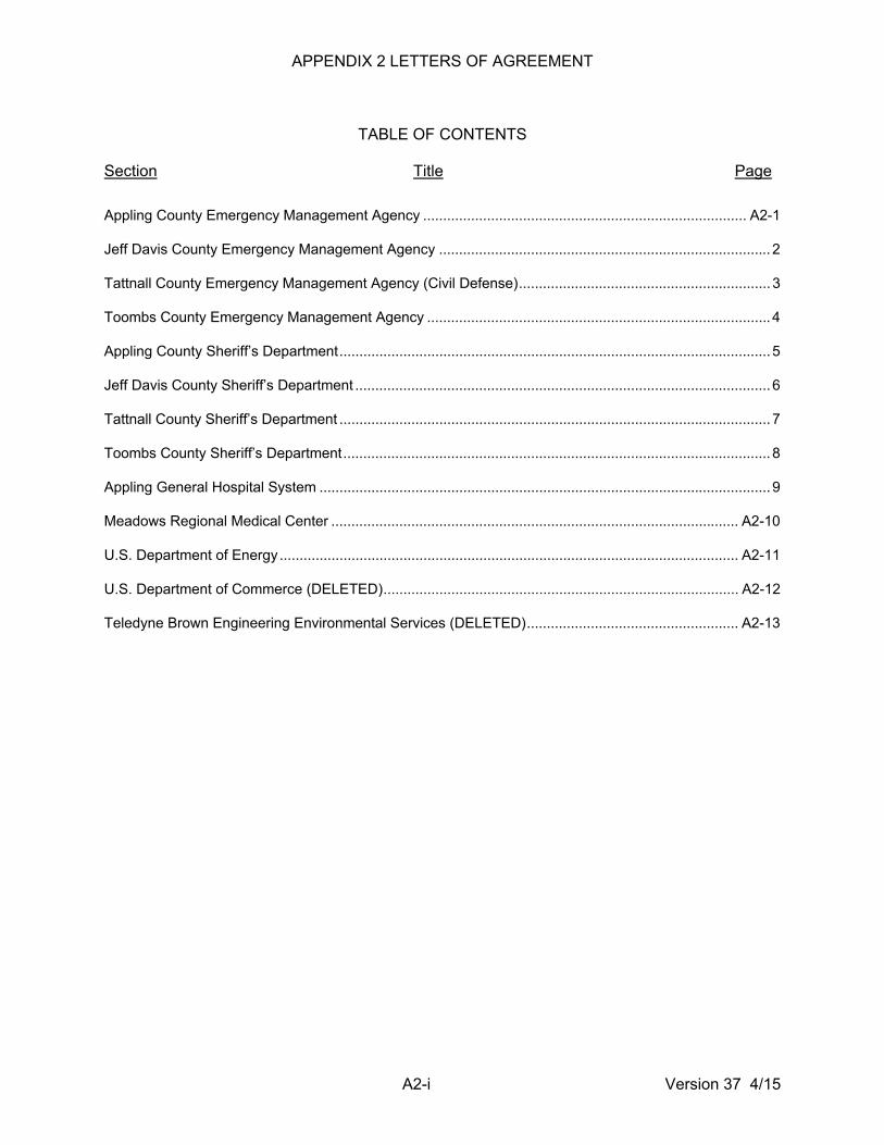
APPENDIX 2 LETTERS OF AGREEMENT
TABLE OF CONTENTS
Section Title Page
A2-i Version 37 4/15
Appling County Emergency Management Agency ................................................................................. A2-1
Jeff Davis County Emergency Management Agency ................................................................................... 2
Tattnall County Emergency Management Agency (Civil Defense) ............................................................... 3
Toombs County Emergency Management Agency ...................................................................................... 4
Appling County Sheriff’s Department ............................................................................................................ 5
Jeff Davis County Sheriff’s Department ........................................................................................................ 6
Tattnall County Sheriff’s Department ............................................................................................................ 7
Toombs County Sheriff’s Department ........................................................................................................... 8
Appling General Hospital System ................................................................................................................. 9
Meadows Regional Medical Center ...................................................................................................... A2-10
U.S. Department of Energy ................................................................................................................... A2-11
U.S. Department of Commerce (DELETED) ......................................................................................... A2-12
Teledyne Brown Engineering Environmental Services (DELETED) ..................................................... A2-13
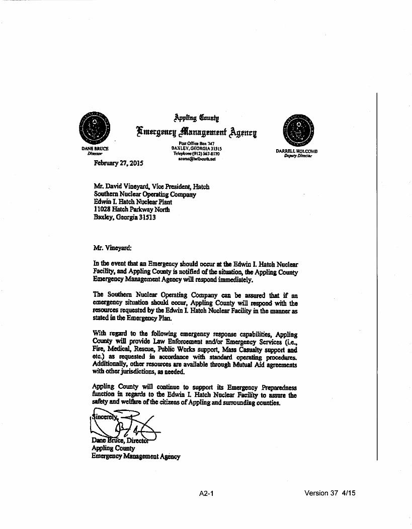
~ling luuadJ ~mersantv c:Mamrsem2nf h•ttcu
DANEU.Uc:E blff:tklr
POJt Office Sox 7~7 BAXLEY, OEOR.<iiA l U l5 Tclrpbonc{9l2)367-&170
[email protected] DA.RRPJ.L HOLCOMB
Dllflf1 Dllftkn'
February 27,2015
Mr .. David Vineyard, Vice President, Hatch Southem Nuclear Operating Company Edwin I. Hatch Nuclear Plant 11028 Hatch Parkway North Baxley, Georgia 31513
Mr. Vineyard:
In tho event that an Emergency should occur at the Edwin I. Hateh Nuclear Facility, and Appling County is uotific:d of the situation, the Appling County Emergency Management Agency will respond immediately.
The Soulbem Nuclear Operating Company can be assured that if an emergency situatioD should occurt Appling County will respood with the resources rcquestr:d by the Edwin I. Hatch Nuclear Facility in the manner as stated ill tbe Emergency Plan..
With n:gard to the following emergency response capabilities. Appling County will provide Law Enforcement and/or Emergency Services (i.e~ Fire, Medical, Rescue, Public Works support, Mass Casualty support and etc.) as requested ill accordaDce with staDdard operating procedures. AdditioDBily, other resources are available throop Mutual Aid agreements with other jurisdictions, as needed.
Appling County will continue to support its Emergency Preparedness functioa in regards to the Edwm L Hatch Nuclear Facility to assure 1he safety and welfilre of the citizeos of Appling and SWTOunding counties.
A2-1 Version 37 4/15

JEFF DAVIS COUNTY EMEAGENCY MAN.4GEMENT AGENCt ..
10PUSI.IeWETYOAM.:
foi~T.GSOFIGL\31539
DIVkl Vineyard Vlcft.Prnldent Nuclear Plant Site Plant Edwin 1.. Hatch 11028 Hatch Parkway Nar1h Ba~ter. Gtorara 31513
February 27.2015
. KAnrt W, LDnO ClDIK
Rt; ASSISTANCE AGREEMENT PLANT HATCH SITE ENERGEH£(
ACM·29 LR .. VPH.019-0288 EP..SSC207 Dear Mr .. Vineyard~
Thl1 letter Ji ta .. unt Southern CompanJ that upon requHt from ~nl Hatch~ state or local authoriUe~ Jeff DIYfa County Era~rgency Management Agency will promptly respond ta any emergency at Plant Hatdt In the m.nner u stated in our Emergency Plan1.
I hive been lltured by au Public Safety Agendes In Jflfl Dlvfs County thlt 1ssets end pe110nnt1 will bit dispatched In auppcrt of any situation that may ne.. This aJso Includes our Mobne Command Vehidlt.
PleBH be nsured of our cooperation.
Chartn Wascfin. EMA Director
A2-2 Version 37 4/15

F.brutry 27, 2015
Mrt David Vlnlptd Vice President Nuclear Plant Slta Edwin L H.tch NudQr Pl~nl 11021 Hltdl hrfnoy NOith a.dey, Gecqia 31513 •
111 1M event that '.n emerpncy should oc:cur at dtt Edwin L Hatch Nud•• FacHJty, and Tattnatr Cotmty Is notified of th1 s1tu1t1on, the Tlttnall County Emeraency Mln•pm•nt Aaency will rtJpond lmmtdllt•ly.
Th• SQuthem Nuclear Dperallns Cornpany e~n H assured thlt If an ema~~ency sltulllon should DCCLIJ', Tlttnall Quaney wiN respond with 1ta1 ruaurms qquestlel by the £dwln r. HitCh Nudtlr fadlilY In lh• ntlnnlt as ltlttd In thl Emerpnqr Plan~
With reprd ID the foUDwsna tmetltftcv ~e~panse cap• bRides. r-..u ~nly will pravlde 1.tw Enforcement and/or En'llftCV 5ef\'lce$ (Le._ Fire, Medial. RIKYI, Public WDrka SUpport. Mus C.uslrfty Support and ICC!.) q requested in accardlnce with dllldard op11'1tln1 · ptOCidures. Addltlonllly, other resources 1re avalllbfe thraulh M~11 Aid •sreements wlth Dth• jurlsdJctJons .. u naeded.
Tattn~l County wiD continue to support Its Emarpncy Preparedness functions In repnfs to the edwm 1 .. Hatch Nudiw tradlty to IUUN tht saftty and wilflre of the dtlzens of Tattnalllnd surroundlna countf••·
51n~
Wilt J1o1etS, Director Tattnal County E'~Mtpncy M1napmenc AJ•P.CY
A2-3 Version 37 4/15
PIVIcl VINPrd .•
Toombs~ EmlrpncyMinlpmcnt
JZ1 North WestStiHt
lyons, Geaqla. JOWl
Vb PruldtntNudHr ••ntSitl
1tOU Hndl Plrlcwly
IIIIey, Geoflfl 3151!
In ICCIOI'dlra wlda lhiiiNIInel betwftn the. Taomn COunty Emerprq M~n~pment Aaency end SauthlmNudelt~~ M ~HI1dlllufey.G& Uponnqllatdll
Toombs COUnty Emlrlenc¥ Ml"fftmtnt Apncy wtlt respond ta Jlllnt ~In alll'ltiiJIIII:y stt•11ons.
We wlllmpcnd w11b Toombs Coamty Jher1fP deputies, Toombs CGunty E~Servii:B, Volunteer fila penanll ind equlpmeftt, TDambs ~ Fft/lllscue and Too• COUnty Pubic WOib person11 and lqlip.,.,.., WI WiD support IMSI CISUIIly sltuatlons should 1t be requited.
A2-4 Version 37 4/15

.~ '.. . . .. .. ; . . .. \ ..... · ··-.
;·;
. . :;-'4;~ Aiiistlai:e .. m E~onor Notificitiaa iheiaJf :. •· ··~:.'' .~· , .. , : ~~· .. : ' It<·. ~·. •:. •·
A2-5 Version 37 4/15

JEFF DAVIS COUNTY SHERIFF'S OFFICE
Ma1:cb 9, 1015
DaVid Viuyud
P. 0. BOX 237 • HAZLEHURST. GEORGIA31639 PHONE (912) 375-6600 or (912) 375-6801
Vice P~e•idut lluelur Plane Site Plct !dviD Hatch 11028 Batch Parkway Ho~th JIIIXley, Gaoqia 31513
Dear Hr. V:l.Deyard
DUANE KIRBY Drug~r
11M LACEY ~r
Should aD emeraea.cy occur at Plaa.t Hatch, Tbe Jeff Dari1 County Shariff' • Office i.e prapftM to fulfill tlaa l'Upoue:Lb:Uicie• autl:lnad ':I.D the Jeff Dav:f.a County bez:seDCJ Plan.
Tbe auistmce lJe cau p~:ovtde Would U\clude, but :b not l:bd.ted to:
1) !J:aff:la Control 2) Police Caa.t~l 3) lack up c:o..m.tcat1.on 4) -.ac:uatioll As.Utaa.ce
We vU1 c:ot~t:l.aue to aeeut yau~: office f.D uy ny pa•dble to aaaure tba •afecy of the c~t1aeas of Jaff Davia Count, and •ur~cundiaa eouutiaa.
~~1-l'nltOD Bohallrm, Sheriff Jeff D&YU Cwnt7 Shariff' e Offiee 15 Mlic Safaty Dri.va P.O. lox 237 Bazl.ehunt, Geor&U 31531
A2-6 Version 37 4/15

TA TINALL COUNTY SHERIFF'S OFFICE rn ''llUf?.ftm ,, m.tn• Oulial Rpb. !lsdlt
P.O. Bot5ol5 REIII!I\11J.F. CF.ORC~IA3045J
February 26, 201 S
Soulhcm ~UclearOperasins Company; Jnc~ Plant Edwin I. Hatch 1021 Hatch Parkway Ncnb Boxley~ Ga. 31515
Subjc:d: Lett~:r or Apm~nl
t"u:(,J2)55'147"d
ln aeaJrdancc ~ilh OUl' ll&tcr o( llgrealenl, the folJO\\ing informllliUD is DflirmL'Ci: '•As SOOD liS notified by Edwin L Hatch Nucla PIAn~ Scale G.E.M.A.~ or local authorities, that 111 incident lms occuned ot Pl11nt Hat~:h, lht Sheriffs Office orTatlnall Count)' "ill promptly respond in rm: monacrscatcd in the Tattnall County lioeJgency and Disaster Opemtions Plan."
Please be llSSW'Cd ofdtc fuU cooperalion of1he Tat1nDll County Sheritrs Office ..
A2-7 Version 37 4/15

Toombs eoun~·~h~~~~· .. o~~ · 357 Northwest Broad Street Suite 1 Lyons, GA 30436
BusinesS Phone 917~26.6778 FAX 912.526.7749
25 February 2015
David VIneyard VIce President Nuclear Plant Site Plant Echlln I. Hatch 1 1028 Hatch Parkway North Baxley4 Georgia 31513
Re: Updated Agreement LeHer 2015
Mr. VIneyard,
The Toombs County Shertrrs otrJCe will proVide needed support to Pfant Hatch fn 1he event of a plant emetgency. As alated In the pmfous agraement wa wftl asslal with tramc central and other support as far as our resources wftl pennlt. If you have any questions please feel free to ccnlact me.
Sincerely. ~ htJd Sheriff
ALK.Jr .lbeb
A2-8 Version 37 4/15

' \·
SttaetAddtea fA E. Tolllon stnet •
l I ••. ~ 31513 Jill
Fdlruaq 21, 20JS
C.wld v.,., Vkl Prllldeal lhrla L Mia NIIClnr 'fill P.O.Ial2011 lldly,a.at&31S15
O.Mr. ViJcJri ' . . '
APJ]iql!llaprq~StnalldiMBullylltdAppira~Ht¥W~IIIllmall!r a ,,. • .,_ •lllplld rDIII~ llwotYJailfcJcnal crflfJIII'J~-..Irilll&hm,~
' ICftllllll ia 1111 ~ Lllllli Nllilatriwer P~. • . ,.. "
TMy..U. Otoqla Power~(l ftllaclall)' ....... tr., adlblau of'CMpa.t AabUaraSimMtqa .... w1M 11Q IIIIJilUirtdtf'IIIINullllr ~a.Jssl~or aim. flrdlta...t ofpllr.ts fiPOI'CICD1driitlftiiiMdtll. n. fiiDDradlapecfal~lf'iiD'u 1111)'111~811 MC1a11Y ID .... .., equl,_r,.
W.pra: i11114 ,..,..St,yT• WIM.IIo.,detlililll..._labetlba ll'dleaat Df'dlat ,...." .. lalp ... IIIIIIL II fa ...... •pcaMtel will ..._ID ..... ,._.a lnlniCdoa hilL M.C. rapidiDa dis Pfizaof.ctbladpddplllll ,_..ddllad ..,.*-... ,.or.._ W•.-ln•ICII•8k. whtftWicatla_,.....)WIJor~•• ........
A2-9 Version 37 4/15

Febnwy 25, 2015
David Vineyard Vice-President Edwin L Hatch Nuclear Plant 11021 Hatch Parkway Baxley~ Oeorgia 31$13
Dear Mr. ViDC)'Il'd:
J( MEADOWS
REGtONAl MEDICAl CENTER
'Repdmg your request concemins ~ navlcttar of agree~nant from our orpnizatioo. please know that Meadows Re&fomal Medical Center will provide medical aufst.IUK:e in case of RmCI'Jmc)' or acciclcnt at PliDt Hateh.. We are wiUinJ to accept casualties arisiDJ fiom mdiatioo accidcats at Plul Hatch consistent wilh our ficilities, pcrsoan~ IQd qbiJity to handle the numbas involved.
Our Radiation Dccontmninatfoa Umt consist& of one room and i1 avllilab1c to 'handle casualties ftDm a mdintion accidcnL
Please feel he to cootac:t me should you have any questions.
Sincerely,
I~~~ J. Alan Kcat, President & CEO
AX:wm . ltrvirleyard
ONE MEAOOWS NKWAY., PO ac»c: 1041•VII:W.IA ~ 30f15·1041
A2-10 Version 37 4/15

Mr. David R.. Vim:y.srd Viec Pn:sfdent Nur:lcar Pl11nt Sitv Phm: Ed,vln I. Halch
National Nuclear Securily Admlnistratfon
PO la~A AllM Snlllh tl,.,mlla.• 7!»1n~
Mareh 5, 2015
Somlu:m NPclaar Opcr.a1~nu Comp:uw. t~ ll 02S Halch Parkway North Ba:clcy. OA 31513
Dc::u Mr. Vineyard:
Subjm: Dep~manl or E'ncrm' (DOE}~Iiomtl Nu~:lcar Security Administl'lllinn (NNSA) t.eltcr of Asrmncnt ror Emerap:11q.• Support
Assunmcu is hereby sh·cn that dtc: OOE>NNSA will n=tpund co requc:sll for rodic.tloc;ical ossist;ancc from ltccnsl!CS ;nd Fc:dcra1 and Shltu agencies UJ\'01\·ed in or t1'gnizanc of 111 inciden1 believed to in\·oh·c 10un:c. by.produca. ar ath~ SJ1CCht1 nudcur ~•erial u dclinc:d by lhc Alomf~ EnflrJ:lY Aa of 1954. as .umcndad( or olher ic:JnizinJJ radiation sPun.w. Auistu~o~ as indiwc:d abo\oe would be tnade 1u.ailable 1o the Soulhr.m Jtlu~l• Opcr.uiny Company "ill rcspec:t lO incident~ occurring at i'b 1•1-anl Edwin I. llGt.:h upon n:quC!!It zmd in consnmmc~ with n.'SpOnsc: aeti\ilics conduc:lcd by StAte,. local. and privute indusuy emqcney n:sponsc personnel.
Unless OOSINNSA or a DOI::fNNSA c:an&r.N-1\11' is n:apansiblc ror the 1M.1Miy. ianmna mdiation source, or rildio=lh~• anatmul iitYo\\•ltd in tlle incident. DOE·NNSA radiologiea.! ISSiJtmCC will be timlfc:d ra lld\'iCC:. dctcclian and id .. -utifaliun of radioa.:ti\•c mnlcrials, nnd/or monitoring and a.ssessmenl actions essential for the contnll or lhc immt:dr.uc hazards to haallh 02ad Aruty. DOEIN'~SA rtldinlogicul UStii!iliU\t:u will be aenninared \~hen il is no lonsc:r needed or the noccuary usistuce l!l cvailabtc linm SUJ.tc. local, or ~mman:i:d sc:n.'ic:es. Thcref~ responsibility for post-acciclcnl racovcry. im:luding rudlscr actions for the pratcclion or individuals and d~e public: haahh and sa(c:ty. shnuld he assumwl by du: Jppmprialv ao\'c:mmL-nt 1,pncy or privAte: authority as 10011 as emcrgw:ncy condition~ an: stabilized.
Requests for DOEINNSA raclioloa;icalusista111.-c mar be din:cted to the Sa,··gnnah .liver Sile Operations Center :d the l4·hour cmt:rJt"':DD:Y iiMiSI:tm= lclcphonc number .. (SOl) 7l5~3lll. Questions rcprding the DOEINNSA Rlildiolosic;J Emergency R.espons~: ASS&.1s m:ay be din:c:tcd 1u me at (81)J]95l·661J.
Sinccr~:ly,
~\. ~· £1.-..Jx--' Christina ·r. l:ml'ards Reyiunal Rcspou: Cuurdinutnr OOER~:tdan 3
A2-11 Version 37 4/15

A2-12 Version 37 4/15
Letter of Agreement DELETED

A2-13 Version 37 4/15
Letter of Agreement DELETED

APPENDIX 3
MEANS FOR PROVIDING PROMPT ALERTING AND
NOTIFICATION OF THE PUBLIC (PNS)

A3-1 Version 37 4/15
APPENDIX 3 – MEANS FOR PROVIDING PROMPT ALERTING AND NOTIFICATION OF THE PUBLIC PROMPT NOTIFICATION SYSTEM
A. INTRODUCTION
Prompt alerting and notification of the public within the plume exposure pathway EPZ are the obligation of State and local government or other responsible authority. The responsibility that means exist for this purpose rests with the licensee. An overview of these means is given in this Appendix. A full Alert and Notification System (ANS) description is provided in the FEMA approved Alert and Notification System Design Report (ANS-HNP-001) located in the SNC document management system. Initial notification of the public will occur in a manner consistent with assuring the public health and safety. The design objective for the system is to meet the acceptance criteria provided in a subsequent section of this Appendix. The design objective does not constitute a guarantee that prompt notification can be provided for everyone with 100-percent assurance or that the system when tested under actual field conditions will meet the design objective in all cases. The ED at HNP is responsible for notifying appropriate State and local response organizations, as well as plant emergency personnel, in the event of an emergency. The ICs for each emergency class are delineated in Section D in the main body of this Emergency Plan. The capability for 24-hour-per-day alerting and notification of offsite response organizations and plant emergency personnel is described in Section E. In the event of a declared emergency at HNP, initial alerting of the public would be by the siren system and EAS. The State of Georgia or Appling County EMA will activate the siren system when it is appropriate to alert individuals within the 10 mile EPZ of an emergency at Plant Hatch. Following activation of the siren alerting system, notification will be performed via local radio and television stations (Emergency Alert System).
B. CONCEPT OF OPERATIONS
The ANS consists of a primary ANS and a backup system should there be a failure of the primary system:
• Primary - Sirens and Emergency Alert System (EAS) stations
• System Backup - Reverse calling system
The concept of operation for the system is as follows:
The Primary ANS has two communication pathways. The first pathway is through the primary agency (on site) via the UHF or VHF radio. Should the primary agency fail to activate the system, the secondary pathway will be utilized by the secondary agency (off site in Toombs County). If neither agency can activate the system, the backup system will be utilized to notify the residents of the 10 mile EPZ.

A3-2 Version 37 4/15
The siren alerting system consists of Whelen Model 2900 series electronic omnidirectional sirens. The siren system sound coverage is such that a loss of a single speaker-driver can be tolerated on any siren without reducing siren coverage below the minimum required for populated areas within the EPZ.
The EAS provides government officials the capability to provide immediate communications and information to the general public at the State and local area levels during periods of emergency. EAS activation procedure will be in accordance with State EAS plans.
Special Alerting and System Backup
Special alerting will be accomplished through the use of a calling system. Special alerting will be initiated in the event of a failure of the system to activate multiple sirens resulting in a loss of coverage in any area. Special alerting may be initiated for a predefined area, a user specified area, user defined groups, or the entire EPZ.
The calling system will serve as a complete backup to the ANS. The system will provide both alerting and notification of EPZ residents independent of the alerting capabilities provided by the installed siren system and notification capability of local radio and television stations.
The calling system is designed to be able to contact residents within the EPZ via telephone or cellular phone with a custom message specific to the event. Thus, it meets or exceeds the relevant criteria for backup notification of area residents and businesses.
C. CRITERIA FOR ACCEPTANCE
The minimum acceptable objectives for coverage by the system are:
Capability for both alerting signal and an information or instructional message to the population on an area-wide basis throughout the 10-mile EPZ, within 15 min.
The alerting system will assure direct coverage of essentially 100 percent of the population within 10 miles of the site.
The Acceptance Testing Plan (ATP) focused on demonstrating the operational features of the siren alerting system such as diagnostic tests, silent tests, and full sound volume tests.
A detailed account of the testing process is available in the ANS Design Report.
D. PHYSICAL IMPLEMENTATION
In the event of an emergency, the licensee has developed and will maintain plans, systems, procedures, and relationships that are effective in notifying appropriate governmental and other responsible authorities. These authorities will have available to them the means for alerting and notifying the general public and for advising of appropriate responses by the public.

A3-3 Version 37 4/15
The communications network utilized between the plant and the responsible authorities is described in section E. Notification of the licensee's emergency response personnel is described in Section E of the main body of this Emergency Plan. Notification of State and local response organization personnel would be described in their respective emergency plans.

APPENDIX 4
TYPICAL EMERGENCY EQUIPMENT LISTS

A4-1 Version 37 4/15
TABLE A4-1
CONTROL ROOM EMERGENCY EQUIPMENT (TYPICAL) 1. Survey instruments 2. Complete sets of protective clothing 3. SCBAs 4. Spare air cylinders 5. Spare batteries 6. Radiation Protection and Monitoring Procedures 7. Potassium iodide tablets

A4-2 Version 37 4/15
TABLE A4-2
TSC EMERGENCY EQUIPMENT (TYPICAL) 1. Survey instruments 2. Digital alarming dosimeters 3. Air sampler 4. Radiological signs and inserts 5. SCBAs 6. Potassium iodide tablets 7. Plant radio

A4-3 Version 37 4/15
TABLE A4-3 (SHEET 1 OF 2)
SIMULATOR BUILDING EMERGENCY EQUIPMENT (TYPICAL)
Simulator Building Supplies 1. Survey instruments (and check sources) 2. Digital alarming dosimeters 3. OSLDs 4. Air samplers 5. Silver zeolite cartridges for air samplers 6. Particulate filter papers for air samplers 7. Smears 8. Plastic bags 9. Radiological signs and inserts 10. Barrier ropes 11. Tape 12. Plastic sheeting 13. Paper coveralls 14. Paper shoe covers 15. First-aid kit 16. Flashlights 17. Spare batteries 18. Potassium iodide tablets 19. Emergency Implementing Procedures; checklists and data forms 20. Clipboards, writing materials, and secretarial supplies 21. Area maps 22. Portable radios 23. Plant radio 24. Respirators (for field monitoring team use)

A4-4 Version 37 4/15
TABLE A4-3 (SHEET 2 OF 2)
SIMULATOR BUILDING EMERGENCY EQUIPMENT (TYPICAL)
Emergency field-monitoring materials and equipment 1. Survey instruments (and check sources) 2. Digital alarming dosimeters 3. OSLDs 4. Portable air sampler 5. Silver zeolite cartridges for portable air sampler 6. Particulate filter papers for portable air sampler 7. Sample counting equipment 8. Field-monitoring log forms and log books 9. Area and road maps 10. Field-monitoring and sampling procedures 11. Clipboard and writing materials 12. Smear record folders 13. Plastic sample bags and bottles 14. Spade 15. Gloves 16. First-aid kit 17. Flashlights with spare batteries 18. Potassium iodide tablets
A4-5 Version 37 4/15
TABLE A4-4
OSC EMERGENCY EQUIPMENT (TYPICAL)
1. Survey instruments (and check sources) 2. Digital alarming dosimeters 3. OSLDs 4. Air samplers 5. Silver zeolite cartridges for air sampler 6. Particulate filter papers for air sampler 7. Survey logs 8. Smear record folders 9. Plastic bags 10. Radiological signs and inserts 11. Barrier ropes 12. Tape 13. Plastic sheeting 14. Absorbent material 15. Complete sets of protective clothing 16. Respirators 17. Respirator particulate filters 18. SCBAs 19. Spare air cylinders 20. Plant radio 21. Radiation Protection and Monitoring Procedures 22. Potassium iodide tablets 23. Emergency Plan Implementing Procedures; checklists and data forms 24. Clipboards, writing materials, and secretarial supplies 25. Plastic rainsuits Decon kit 1. Decon agents 2. Paper towels 3. Soap powder 4. Pumice-base soap 5. Scrub brushes 6. Paper coveralls 7. Paper booties 8. Decontamination Procedure

A5-1 Version 37 4/15
APPENDIX 5
EVACUATION TIME ESTIMATES FOR
HNP PLUME EXPOSURE PATHWAY EPZ

A5-2 Version 37 4/15
Evacuation Time Estimates for the Edwin I. Hatch Nuclear Plant In order to ensure the safety of the public living in the vicinity of nuclear power plants in the nation, the U.S. Nuclear Regulatory Commission (NRC) requires licensees to develop and update evacuations times estimates (ETEs) for areas within the emergency planning zone (EPZ). Updates are required following the availability of data from the decennial census (10 years) or when the sensitivity factor for changes in population within the EPZ has been exceeded. ETE population reviews will be conducted annually. This appendix contains information from the ETE update performed in 2012. This update implements the requirements of the revised regulations relevant to ETE updates in accordance with the guidance provided in NUREG/CR-7002, Criteria for Development of Evacuation Time Estimate Studies and the requirements in 10 CFR 50, Appendix E, Sections IV.3 and IV.4. Southern Nuclear Operating Company (SNC) contracted IEM to estimate evacuation times for the 2012 populations within the 10-mile plume exposure pathway emergency planning zone (EPZ) surrounding the Edwin I. Hatch Nuclear Plant (HNP). This appendix provides a summary of the final report describing the methods used to obtain population data and to estimate evacuation times and estimated population figures, evacuation road network information, and ETEs. The report provides a breakdown of the population by geographic areas and protective action zones (PAZ). Five categories of population are identified in the report:
• Permanent residents • Transient population • Transit dependent permanent residents • Special facility residents • Schools
The permanent resident population is made up of individuals residing in the 10-mile EPZ. The total year 2012 permanent resident populations within the 10-mile EPZ for HNP are estimated to be 8,609. The transient population consists of workers employed within the area, recreational sportsmen, and visitors. The total transient population within the 10-mile EPZ is estimated to be 1,841, which includes 657 workers at HNP. The populations of two public schools and one state-sponsored special facility in the HNP EPZ were identified. In these analyses, the study team contacted the schools and the special facility within the EPZ area to collect current enrollment and staff figures. The total peak population for the schools is estimated at 977, and the special facility is estimated to be 66. Transit dependent permanent residents in the 10-mile EPZ are estimated to be 74. This study also considered the voluntary evacuees, who are also known as shadow evacuees that reside within 10 to 15 miles from HNP.

A5-3 Version 37 4/15
Evacuation Time Estimates for the Edwin I. Hatch Nuclear Plant IEM utilized a computer traffic simulation model, PRV Vision VISUM, to perform the ETE analyses. For the analyses, the 10-mile plume exposure pathway EPZ was divided into 17 unique geographic areas based on 2-mile, 5-mile, and 10-mile radius rings, the 16 22.5-degree PAZs, as well as keyhole and staged evacuation logic. In order to represent the most realistic emergency scenarios, evacuations for the 17 geographic evacuation areas were modeled individually for the midweek daytime, midweek – weekend evening, and weekend daytime scenarios. Each of these scenarios was then considered under both normal and adverse weather conditions using the 2012 population estimations. A total of 102 evacuation scenarios were considered to represent different wind, temporal, seasonal, and weather conditions. Both 100% and 90% ETEs for each scenario were collected. The 100% ETEs for 2012 normal weather conditions ranged from 2 hours 50 minutes to 3 hours 35 minutes. The 100% ETEs for 2012 adverse weather conditions ranged from 2 hours 55 minutes to 3 hours 55 minutes. The 90% ETEs for 2012 normal weather conditions ranged from 1 hour 35 minutes to 2 hours 45 minutes. The 90% ETEs for 2012 adverse weather conditions ranged from 1 hour 40 minutes to 3 hours. The factors that contributed to the variations in ETEs between scenarios include differences in the number of evacuating vehicles, the capacity of the evacuation routes used, or the distance from the origin zones to the EPZ boundary. The factors that contributed to the variations in ETEs between scenarios include differences in the number of evacuating vehicles, the capacity of the evacuation routes used, or the distance from the origin zones to the EPZ boundary. Based on the data gathered and the results of the evacuation simulations, the existing evacuation strategy was determined to be functional for the 2012 conditions, given the lack of severe congestion or very high ETEs. Recommendations were provided for enhancements to improve the evacuation time estimate. Assumptions utilized in the ETE will be reviewed when evaluating changes to roadways or evacuation networks to ensure the results of the ETE remain valid. Changes in population will be evaluated utilizing the sensitivity factor developed during the ETE analysis. The full Evacuation Time Estimate was submitted for NRC review in accordance with NRC regulations 10 CFR Part 50, Appendix E, Section IV.3. Following the NRC review, the results of the study and recommendations will be reviewed with applicable offsite agencies. The review will focus on the utilization of the results of the evacuation simulations provided in the ETE for comparison to existing protective action strategies. Modifications, if any, will be incorporated as part of the ongoing emergency planning process. (Reference: Annual ETE Review document ETE-HNP-002; ETE document ETE-HNP-001).

APPENDIX 6
TYPICAL EMERGENCY IMPLEMENTING PROCEDURES

A6-1 Version 37 4/15
APPENDIX 6 – TYPICAL EMERGENCY IMPLEMENTING PROCEDURES Procedure No. Procedure Title 73EP-EIP-002-0 Recovery 73EP-EIP-005-0 On-Shift Operations Personnel Emergency Duties 73EP-EIP-009-0 Nuclear Security Duties 73EP-EIP-011-0 Assembly, Accountability and Evacuation 73EP-EIP-012-0 Search and Rescue Team Duties 73EP-EIP-013-0 Contaminated Injury and First Aid 73EP-EIP-014-0 Internal Survey Team Duties 73EP-EIP-016-0 TSC HVAC Operation 73EP-EIP-017-0 Emergency Exposure Control 73EP-EIP-019-0 Rally Point Team Duties 73EP-EIP-020-0 Offsite Environmental Monitoring During Emergencies 73EP-EIP-021-0 Alternate OSC Activation 73EP-EIP-023-0 Core Damage Assessment 73EP-EIP-062-0 OSC Activation 73EP-EIP-063-0 TSC Activation 73EP-RAD-001-0 Radiological Event 73EP-RAD-006-0 Repair and Corrective Action During a Radiological
Emergency NMP-EP-101 EOF Activation NMP-EP-102 EOF Manager NMP-EP-103 Licensing Support Coordinator NMP-EP-104 Dose Assessment
Procedure No. Procedure Title
A6-2 Version 37 4/15
NMP-EP-105 EOF Technical Supervisor NMP-EP-106 EOF Support Coordinator NMP-EP-107 EOF Security Coordinator NMP-EP-108 Offsite Response Coordinator NMP-EP-110 Emergency Classification and Initial Action NMP-EP-110-GL02 HNP EALs – ICs, Threshold Values and Basis NMP-EP-111 Emergency Notifications NMP-EP-111-002 EMERGENCY NOTIFICATION NETWORK
COMMUNICATOR INSTRUCTIONS – HATCH NMP-EP-112 Protective Action Recommendations NMP-EP-135 Alternative Facility Setup and Operation

APPENDIX 7
EMERGENCY OPERATIONS FACILITY

A7-1 Version 37 4/15
APPENDIX 7 – EMERGENCY OPERATIONS FACILITY A. INTRODUCTION
A.1 Purpose
The purpose of this appendix is to outline the function of the Emergency Operations Facility (EOF) for the Southern Nuclear Operating Company (SNC). Additionally, this appendix delineates the actions to be taken by SNC Corporate Staff in the event of an emergency at any (SNC) site.
A.2 Scope and Applicability
This appendix provides the framework for operations of the EOF for SNC. This appendix is an integral part of the site-specific emergency plan(s). This appendix may be implemented to coordinate a SNC response to an emergency at any SNC facility or in response to a transportation accident involving radioactive material. Additionally, this appendix provides the mechanism for obtaining and providing additional emergency response support and resources to SNC site(s) in the event of an emergency. The SNC Corporate Staff will be responsible for offsite emergency response support and resources as requested. Overall management of the emergency will be accomplished at the specific site(s) [Vogtle Electric Generating Plant (VEGP), Hatch Nuclear Plant (HNP), and Farley Nuclear Plant (FNP)].
A.3 Summary
The site-specific Emergency Plan is activated by the ED. Upon notification of an ALERT or higher classification or as directed by the ED, the EOF will be activated as described in emergency implementing procedures. When notified, the designated corporate emergency organization management report to the EOF to be briefed on current conditions and perform their assigned tasks. Each manager's support staff will operate from that group's office area. Offsite support personnel and equipment will be dispatched to the site Operations Support Center (OSC) or Technical Support Center (TSC) upon request from the specific site ED. The corporate emergency organization will provide offsite emergency response support and resources to SNC sites 24 hours per day until the emergency has been terminated. The EOF will be activated for an ALERT, SITE AREA, or GENERAL emergency classification. This facility will be operational within about an hour of the initial notification. SNC’s goal is to begin notification of all required on-call Emergency Response Organization (ERO) personnel as soon as practicable, within 15 minutes, following the declaration of an Alert emergency or higher emergency classification at any SNC site. Minimum EOF staff for facility activation will include the EOF Manager, the Dose Assessment Supervisor, the Dose Analyst, the Field Team Coordinator, the ENN Communicator, and the Licensing Support Coordinator. Access control for the EOF is established through the use of electronic card readers.

A7-2 Version 37 4/15
During the emergency, the ED will normally be located in either the TSC or Control Room at his/her option. The ED is responsible for the management of the emergency response. Specific duties and responsibilities are provided in the site-specific Emergency Plan and Emergency Plan Implementing Procedures. SNC has taken precautions to ensure that the EOF can be quickly accessed and made operational within about an hour of the initial notification and is safeguarded against unauthorized personnel. The common EOF is located in a secure building. The building itself has posted security guards and video surveillance cameras. Any outside doors that do not have security guards are accessible only by SNC ID badges. Additionally, the EOF facility door is accessible only to people with ID badges that have been pre-approved for access. If an event were to occur during off-normal hours, a guard will be posted at the main entrance to Building 40 to allow access to offsite agency or other responders without predesignated ID access.
B. EOF ORGANIZATION
The EOF Organization consists of selected management and staff members located in the SNC Corporate Office. This organization is responsible for providing offsite emergency response support and resources, as needed. The EOF Organization is displayed on Figure A7-1 and typical duty assignments are shown in Table A7-1. This organization may be supplemented or reduced by the EOF Manager, as required, to respond to the specific emergency situation but will not be reduced to below the minimum staff as specified in A.3 above. SNC normally maintains ERO positions in a duty rotation. Several positions have been designated as plant specific and, as such, have personnel designated for each of the three sites. Specifically, each of the following EOF positions has site-specific personnel designated:
• EOF Manager • EOF Technical Supervisor
In order to augment additional staff that may be needed in the unlikely event of a multisite accident, SNC will reactivate its ERO notification system. When the EOF is activated, all EOF staff pagers are activated, and all EOF personnel are expected to report to the EOF. Personnel who are not needed to augment positions are briefed and dismissed with a standby status. B.1 Emergency Operations Facility (EOF) Manager
The EOF Manager manages the following activities: • Overall direction and control of the offsite response for SNC.
• Communication of radiological information to State and local emergency response agencies as needed.
• After consultation with the ED, provides support for initial activities associated with planning for recovery operations.

A7-3 Version 37 4/15
The duties and responsibilities of the EOF Manager will be assumed by designated SNC corporate personnel. The designated individual will be assigned according to a predetermined rotation schedule and will typically have either previous plant-specific SRO background or long-term supervisory/management experience. The duties and responsibilities of the EOF Manager are as follows: 1. Manage the EOF and direct the activities of the EOF organization.
2. Ensure activation of the EOF at ALERT or higher classification, or as directed by the ED.
3. Support site efforts for the following:
• Determining the cause of the incident.
• Assessing the overall damage, including personnel, equipment, systems, facilities, and/or fuel.
• Developing recovery plans.
4. Keep corporate management informed regarding the emergency response and emergency classification upgrades.
5. Ensure that the joint owners, as applicable, are kept apprised of significant changes in the emergency status including upgrades and terminations.
6. Keep the GPC/APC public information director fully apprised regarding the status of the emergency.
7. Identify the available resources within and outside the company to assist in mitigation and recovery, as necessary.
8. Procure outside services and equipment, as necessary.
9. Obtain assistance from SNC Environmental Services regarding nonradiological and hazardous materials environmental considerations.
10. Request assistance from legal counsel as appropriate.
11. Coordinate NRC inquiries/activities requiring a response from the Corporate Office. Obtain licenses and/or amendments to licenses, if required, for repair of the affected unit and disposal of waste products.
12. Approve news releases issued from the Emergency Response Center (ERC) or the Joint Information Center (JIC).
13. Communicate developed PARs to the ED once offsite communication responsibility is transferred to the EOF. The EOF Manager and ED will determine which facility will communicate the PARs to offsite agencies. Normally, initial PARs will be communicated to offsite agencies by the TSC while changes in PARs will be communicated to offsite agencies by the EOF.

A7-4 Version 37 4/15
14. Ensure that necessary support is provided to the SNC Newswriter, the SNC Spokesperson, and the Public Information Director to ensure timely and accurate information flow to the public. An unaffected EOF Manager will be available to assist the affected EOF Manager in Company Spokesperson interface activities.
B.2 EOF Technical Supervisor
The duties and responsibilities of the EOF Technical Supervisor will be assumed by SNC corporate support personnel. The designated individual will be assigned according to a predetermined rotation schedule and will typically have plant-specific long-term engineering/design experience. Reporting to the EOF Technical Supervisor are the emergency communicators and the necessary engineering, technical, and licensing personnel needed to support tasks assigned to the EOF. The duties and responsibilities of the EOF Technical Supervisor are as follows: 1. Provide technical interface to vendors, utility groups, consultants, and
technical investigation groups.
2. Assist in establishing a list of plant equipment/system modifications required to bring the plant to cold shutdown, recovery, and/or startup.
3. Develop an engineering support plan compatible with the plant mitigation and recovery plan. Provide engineering support developing site recovery procedures. This plan will include engineering personnel resources.
4. Coordinate the work performed by SNC engineering, Southern Company Services, the architect engineer, the nuclear steam supply system supplier, and other engineering consultants. Coordinate the transmittal of engineering modification/design documents (Design Change Packages (DCP), Request for Engineering Assistance (REA), etc) to the site staff and site and SNC procurement groups.
5. Coordinate the receipt and assessment of technical information related to plant systems and facility operations and submit recommendations to the TSC Manager through the EOF Manager.
6. Provide licensing support, as requested, through utilization of the licensing support.
7. Provide communications support for offsite notifications [(Emergency Notification Network (ENN)], as requested.
B.3 EOF Support Coordinator
The duties and responsibilities of the EOF Support Coordinator will be assumed by SNC corporate support personnel. The individuals designated to assume the position will be indicated on a predetermined rotational schedule. Reporting to the EOF Support Coordinator are the nontechnical personnel needed to support tasks assigned to the EOF. Additionally, the News Writer is matrixed to the EOF Support Coordinator from the corporate communications organization.
A7-5 Version 37 4/15
The duties and responsibilities of the EOF Support Coordinator are as follows: 1. Provide assistance to the EOF Support Coordinator in the Technical Support
Center (TSC) for ordering equipment and materials needed. Establish a standby list of personnel to provide additional technical support, as required.
2. Obtain materials, supplies, and equipment that are needed in the EOF.
3. Process expense accounts, distribute checks from payroll, and conduct other financial aspects of the emergency organization.
4. Provide logistics arrangements for support personnel called in to assist in the emergency, including communications hardware, transportation, food, and lodging.
5. Obtain assistance from corporate financial staff to communicate, as necessary, with banks, financial institutions, investors, joint owners, and insurers regarding the emergency situation.
6. During the initial phase of the emergency, provide the official log of actions and the course of the emergency from the EOF.
7. Provide administrative services such as clerical, typing, and duplication for the Corporate Emergency Response Organization.
8. Provide administrative, logistic, financial, and procurement support as appropriate during the recovery phase.
B.4 Dose Assessment Supervisor
The duties and responsibilities of the Dose Assessment Supervisor will be assumed by SNC corporate support personnel. The individuals designated to assume the position will be indicated on a predetermined rotation schedule. Reporting to the Dose Assessment Supervisor are the Dose Analyst, Field Team Coordinator, Field Team Communicator, and Radiological Status Communicator. The TSC will initially be responsible for dose projection and field team control activities. When the EOF is activated and ready to assume functions of dose projection/assessment activities, then the EOF Dose Assessment Supervisor will coordinate transfer of dose assessment, field team control, and protective action determination from the TSC to the EOF. Coordination will include ED/EOF Manager mutual approval of the transfer with the intention of transferring dose assessment from the TSC to the EOF as rapidly as possible while ensuring a smoothly coordinated transfer of this critical function. The duties and responsibilities of the Dose Assessment Supervisor are as follows: 1. Support the plant dose assessment supervisor as necessary. Be prepared to
assume offsite dose projection if requested. Keep the EOF Manager informed of any offsite dose assessments performed by the site or corporate staff.

A7-6 Version 37 4/15
2. Provide an as low as reasonably achievable (ALARA) exposure review of engineering modifications and tasks proposed by the emergency organization, including necessary documentation of those reviews.
3. Develop methods for treatment and/or disposal of radioactive wastes resulting from the emergency and recovery operations.
4. Compare calculations and measurements with State and Federal groups performing radiological assessments.
5. Coordinate distribution of dose assessment information with offsite authorities.
6. Coordinate assistance to the State for transportation incidents involving radioactive material, as requested.
7. Develop protective action recommendations (PARs) and communicate to the EOF Manager the need for PAR communication once control is transferred to the EOF.
B.5 Security Coordinator
The duties and responsibilities of the Security Coordinator will be assumed by SNC corporate security personnel. The individuals designated to assume the position will be indicated on a predetermined rotation schedule. The duties and responsibilities of the Security Coordinator are as follows: 1. Support the plant security manager as necessary. Keep the EOF Manager
informed of any security events/issues.
2. Provide assistance to the security supervisor at the site, as requested.
3. Establish and maintain access control for the EOF.
B.6 Offsite Response Coordinator
The duties and responsibilities of the Offsite Response Coordinator will be assumed by SNC Corporate Emergency Planning Coordinators and designated staff. The individuals designated to assume the position will be indicated on a predetermined rotation schedule. The duties and responsibilities of the Offsite Response Coordinator are as follows: 1. Coordinate activities concerning the dispatch and update of technical liaisons
to State and local authorities, as appropriate.
2. Monitor EOF functional areas to facilitate coordination between the licensee and State and local agencies.
B.7 Engineering/Technical Support Staff and Administrative Support Staff
1. The Engineering/Technical Support staff and administrative support will report to the EOF, as directed. These job titles refer to a number of individuals

A7-7 Version 37 4/15
performing a variety of designated tasks. Their numbers will depend on the type and duration of the emergency.
2. The Engineering/Technical Support staff are personnel designated by the management of the Corporate Emergency Organization. They provide management, technical, regulatory, and licensing support during an emergency. This staff reports through the EOF Technical Supervisor to the EOF Manager.
3. The administrative support staff are the nontechnical members of the Corporate Emergency Response Organization. They perform duties designated by the EOF Support Coordinator or appropriate manager which include, but are not limited to, the following:
a. Providing clerical and secretarial support to the Emergency organization.
b. Operation of word processors.
c. Operation of telecopiers.
d. Making entries to and retrieving data from Nuclear Network.
e. Retrieval of file documents.
f. Updating status boards using information provided from the sites.
C. NOTIFICATION AND ACTIVATION
Initial notifications of emergency response personnel will follow the guidelines specified in the site-specific Emergency Plan and Emergency Plan Implementing Procedures. This appendix contains the emergency notification of Corporate Management and the appropriate offsite support groups not specified in the site-specific Emergency Plan(s). C.1 Notification of Corporate Management
The On-call EOF Manager will be notified of all emergencies classified at any SNC site. The EOF Manager is responsible for activation of the EOF Staff and notifying the appropriate Corporate Management. 1. The EOF Manager is responsible for assuring that the Corporate Emergency
Organization is notified.
2. The EOF Manager will also be responsible for ensuring that the corporate emergency staff members report directly to the EOF.
3. Notification of personnel may be accomplished through the use of an automated or manual system.
C.2 Notification of Offsite Support Agencies Offsite support agencies will be notified by the appropriate emergency organization member(s) as requested by VEGP, FNP, and HNP.

A7-8 Version 37 4/15
D. EMERGENCY FACILITIES AND EQUIPMENT
Following the declaration of an emergency, response activity will be coordinated at a number of facilities. These emergency response facilities are described in the site-specific emergency plans. The EOF is a common facility for all SNC sites and is described in this section. D.1 EOF Description
The EOF is the central location for management of the offsite emergency response, coordination of radiological assessment, and management of initial recovery operations. The EOF is located in Birmingham, Alabama, and serves as the EOF for all SNC sites (VEGP, FNP, and HNP). The EOF will be activated as prescribed in the site-specific Emergency Plan implementing procedures. From the EOF, SNC corporate management personnel assist the states and other governmental bodies by communicating protective action recommendations approved by the ED to ensure public health and safety. Plant systems information, radiological data, and meteorological data are provided via the SNC Integrated Data Display System to EOF personnel as needed to: assess environmental conditions, coordinate radiological monitoring activities, and recommend implementation of offsite emergency plans. Data displays provide periodic and timely conditions of the affected plant and periodic and timely assessment of radiological conditions in the plant environs. The SNC Integrated Data Display System utilizes data provided by the plant-specific data links. These station data links are described in each site-specific plan. These displays may be either manual or electronic. Data displays are located in the main caucus area of the EOF, dose assessment area, plant status area, and engineering area within the facility. Other displays may be located in the command center area. Data are also available to all State agencies responding to the EOF. Data are available both in the main caucus area and the area designated for the particular State agency. Similarly, these data are available to State and local authorities via a secure network dedicated to data distribution among the various offsite emergency response facilities. The data display system provides the user with a “master view” for the monitoring of multiple site events simultaneously. Data required to support EOF operations are provided by an extensive ring bus transport network. Data may also be obtained manually via telephone from the Control Room and the TSC to the EOF. Contained within the facility will be the manpower and equipment necessary to provide dedicated direct communication links to the plant site(s). In addition, there are commercial and company-wide phone systems to and from the site(s). A communication link will be established and maintained between the EOF and the TSC until the ED determines that the communication link is no longer needed. Other communications equipment accessible to the EOF includes Nuclear Network (an intra-industry computer-based information exchange network), telecopiers, and computer workstations designated for emergency use. The EOF is the distribution center for all field data and sample analyses. This information will be available to county, State, and Federal representatives. The EOF is sized to accommodate 35 persons, including 25 predesignated persons, 9 persons from the NRC, and 1 person from the Federal Emergency Management Agency (FEMA). It is anticipated that representatives from the State(s) of Georgia,

A7-9 Version 37 4/15
South Carolina, Alabama, and Florida will be dispatched to the EOF for an event at specific SNC site(s). The EOF has been designed to accommodate these representatives. Agreements exist between the appropriate State agencies and SNC to ensure rapid response of State personnel dispatched to the EOF. Table A7-4 provides additional information concerning EOF communications capabilities. Upon activation of the EOF, Corporate personnel will provide staffing 24 hours per day until directed otherwise by the ED. The ED, located at the affected site(s), is responsible for the management of the emergency response. Specific duties and responsibilities are provided in the site-specific Emergency Plan. The EOF, which consists of several rooms, is shown, together with the location of key personnel, in Figure A7-2. The EOF is a dedicated facility. The designated emergency planning coordinator for each of the three sites maintains an office within the EOF to ensure readiness and daily operability. Based on the physical location of the EOF, specialized ventilation systems are not required. The EOF ventilation system is consistent in design with standard building codes. Similarly, EOF functions would not be interrupted by radiation releases from any SNC site. Normal power to the EOF is from a reliable offsite source. Emergency lighting is provided by battery operated lights. Backup power for the EOF is supplied by onsite diesel generation. All essential equipment is backed up by the diesel generation system. The EOF is located adjacent to the document management section for SNC. The following records or information are available: • Technical Specifications.
• Selected plant operating procedures.
• Emergency Plans.
• Emergency Plan Implementing Procedures.
• Final Safety Analysis Reports (FSARs).
• State and local emergency response plans.
• Savannah River Site Emergency Plan.
The following records or information can be transmitted to the EOF manually, electronically, or by facsimile: • Environs radiological monitoring records.
• SNC employee radiation exposure histories.
• System piping and instrumentation diagrams and HVAC flow diagrams.
• Piping area diagrams.

A7-10 Version 37 4/15
• Electrical one-line, elementary, and wiring diagrams.
The above records or information are available in current form and updated as necessary to ensure currency and completeness. Operations at this facility are directed by the EOF Manager.
D.2 Contingency Planning Optimum functionality and availability were considered in the decision to locate the EOF in Birmingham, Alabama. At this location, functionality of the EOF would be uninterrupted by radiation releases, natural phenomena, and security based events at any of the SNC sites. Support operations and coordination with Federal, State, and local organizations would continue. If personnel were to be dispatched to the sites, then personal protection equipment would be available from the local emergency management agency or from one of the unaffected SNC plant sites. In the unlikely event that individuals should need to respond to the EOF from within the 10-mile EPZ of any SNC plant, they would be surveyed prior to release by local emergency authorities at the reception centers in accordance with State and local emergency response plans. In the unlikely event that individuals should need to respond to the EOF from within the 10-mile EPZ of any SNC plant, they would be surveyed prior to release by local emergency authorities at the reception centers in accordance with State and local emergency response plans. In the unlikely event that the EOF becomes uninhabitable, resources and personnel will be transferred to the Corporate Headquarters of Alabama Power Company, located in Birmingham, Alabama. These actions will be taken as part of the normal business continuity plan.
E. COORDINATION WITH GOVERNMENTAL AGENCIES
The site-specific Emergency Plan(s) delineate the governmental agencies to be notified and specifies the information to be initially conveyed. It is anticipated that representatives of various agencies will be dispatched to the EOF for an event at an SNC facility. Arrangements have been made between the appropriate State agencies and SNC to ensure rapid response of State personnel dispatched to the EOF. E.1 U.S. Nuclear Regulatory Commission
Coordination with the U.S. NRC may be underway at several locations simultaneously. For details, refer to the applicable NRC response plans. Initial notification of the NRC will proceed as specified in the site-specific Emergency Plan. The resident NRC inspector(s) and plant personnel have direct communications from the site control room to the NRC headquarters in Rockville, Maryland, and to the regional headquarters in Atlanta, Georgia. The resident inspector(s) may be reinforced by additional NRC personnel shortly after notification of an emergency. The ED is responsible for coordinating NRC

A7-11 Version 37 4/15
activities to reduce duplication of effort and reduce impact on the plant staff during the emergency situation. Provisions have been made to have direct NRC FTS lines in the TSC and the EOF during an emergency. This will allow personnel in the control room to continue responding to the emergency while personnel in the TSC or EOF respond to questions and input from the NRC. NRC activities requiring response from the licensee will be coordinated by the EOF Technical Coordinator through the EOF Manager.
E.2 State Governmental Agencies The government notifications are outlined in the site-specific Emergency Plan(s). Coordination of offsite responses to the emergency is the responsibility of State agencies as outlined in the State Radiological Emergency Response Plans.
E.3 Local Governmental Agencies Notification of local government officials is outlined in the site-specific Emergency Plan(s). Coordination with local government agencies will normally be through the responsible State agency.
E.4 Department of Energy Notification of DOE officials is outlined in the site-specific Emergency Plan.
F. OFFSITE SUPPORT
Offsite resources that may be available to support an emergency response effort include, but are not limited to, the following:
1. Southern Nuclear Operating Company.
2. Georgia Power Company.
3. Alabama Power Company.
4. Southern Company Services, Inc.
5. The architect engineers.
6. NSSS supplier.
7. Nuclear industry.
8. Contract laboratories.
F.1 Southern Nuclear Operating Company (SNC)
1. SNC is divided into three projects: the Farley Project, the Hatch Project, and the Vogtle Project. Each of the projects is further divided into a plant staff and a corporate staff. These represent a pool of positions of which approximately two-thirds would be additional assets that could be made available to support an individual site emergency organization, as required.

A7-12 Version 37 4/15
a. Plant Staffs - The permanent plant staffs consist of personnel who possess expertise in at least one of the following areas: operations, maintenance, engineering, administration, or technical support. These personnel would be available to assist in an emergency or recovery situation at an SNC nuclear facility.
b. Corporate Staffs - These staffs consist of personnel who provide management, technical, clerical, procurement, and regulatory support to the nuclear facilities.
F.2 Georgia Power Company (GPC)
1. The GPC Fossil and Hydro Power Generation Department is responsible for the operations and maintenance of all GPC nonnuclear generating facilities, including diesel and combustion turbine facilities. This represents a large source of technical expertise which could provide support to the emergency organization, if required.
2. The GPC Power Delivery Department manages the activities of the divisions
and areas of the company which provide electrical services to customers. This organization has a large resource of people and heavy equipment which may be of assistance following a nuclear emergency.
3. Other GPC assets, including maintenance and repair facilities, training
facilities, engineering staffs, and headquarters personnel represent additional resources available for emergency support.
4. The GPC Central Laboratory has personnel and facilities available to provide
offsite monitoring, sample analysis, and dosimetry processing for the affected site.
F.3 Alabama Power Company (APC)
1. The APC Fossil and Hydro Power Generation Department is responsible for
the operations and maintenance of all APC nonnuclear generating facilities, including diesel and combustion turbine facilities. This represents a large source of technical expertise which could provide support to the emergency organization, if required.
2. The APC Power Delivery Department manages the activities of the divisions
and areas of the company which provide electrical services to customers. This organization has a large resource of people and heavy equipment which may be of assistance following a nuclear emergency.
3. Other APC assets, including maintenance and repair facilities, training
facilities, engineering staffs, and headquarters personnel represent additional resources available for emergency support.

A7-13 Version 37 4/15
F.4 Southern Company Services, Inc. (SCS) SNC has the primary responsibility for engineering support of VEGP, FNP, and HNP. SCS may be utilized in response to a plant emergency or for subsequent recovery operations as deemed necessary by SNC.
F.5 Architect Engineers The architect engineers will provide support as requested through the Engineering Services Manager. The Architect/Engineers are SNC and Bechtel Power Corporation. 1. SNC serves as its own Architect/Engineer. SCS, an associate company to
Southern Nuclear Operating Company, will be used to the extent appropriate in responding to nuclear emergencies.
2. Bechtel Power Corporation, headquartered in Gaithersburg, Maryland, also
performs Architect/ Engineer services for SNC. Bechtel's technical staffs are engaged in all phases of public utility engineering, design, construction, purchasing, inspection, and expedition of materials, as well as consultation on utility operating matters. Bechtel has available a broad range of engineering, construction, and consulting experience. Bechtel's nuclear experience includes engineering studies, the evaluation of reactor systems, safety evaluations, detailed engineering design, construction, and startup and testing of nuclear power facilities.
F.6 Nuclear Steam Supply System Vendor
The applicable NSSS vendor will provide support through the Engineering Services Manager. Plant-specific references to the appropriate vendor are specified in the plant-specific base plans. The NSSS maintains a large staff of technically qualified people in all the engineering disciplines related to the design, construction, and operation of a nuclear power plant. These same skills would be necessary in the evaluation of, and recovery from, an emergency at any SNC site. Assistance would most likely be sought for large- scale core analysis, special tool design, and licensing.
F.7 Nuclear Industry The nuclear industry provides a large reservoir of personnel with a wide range of technical expertise and knowledge. A nuclear industry national inventory of personnel who might be called upon to supplement Company personnel has been developed through the Institute of Nuclear Power Operations (INPO). In addition, a number of utilities have entered into an INPO coordinated Voluntary Assistance Agreement program. This provides a mechanism to draw upon industry resources during an emergency.

A7-14 Version 37 4/15
Support that may be requested from neighboring utilities would include the following: 1. Manpower and equipment to assist in in-plant and emergency field monitoring.
2. Engineering, design, and technical expertise to assist in determining the cause of the accident and to support recovery.
3. Manpower and equipment to assist in maintenance and repairs to the facility.
F.8 Contract Laboratories Contact Corporate Health Physics to request desired vendor to be used.
MAINTAINING EMERGENCY PREPAREDNESS
G.1 Organizational Preparedness 1. Training
Corporate personnel identified in the Emergency Response Organization receive training. The training consists of familiarization with the Site Emergency Plans and applicable emergency implementing procedures required to carry out their specific functions.
The Corporate Emergency Planning Coordinator(s) will ensure that personnel in the Corporate Emergency Response Organization are familiar with the Emergency Plans and able to respond promptly. A training matrix for corporate personnel assigned to the ERO is shown in Table A7-2, and training course summaries are presented in Table A7-3. Training will be documented in accordance with established practices.
The Corporate Emergency Planning Coordinator(s) are responsible for assuring that training is conducted for corporate emergency response personnel each calendar year.
2. Drills/Exercises Drills/exercises will be conducted each calendar year to test the performance of implementing procedures, personnel, and emergency equipment. These drills/exercises will be conducted with each SNC site. SNC’s goal is to activate the EOF in support of all site activities that involve TSC activation. EOF activation is required at least three times annually (one scenario per site per year) in accordance with the existing emergency plans. At least one activation every 5 years will require a concurrent EOF support response for more than one SNC site. Each drill/exercise will test, as a minimum, the communication links and notification procedures to assure the prompt notification of the corporate staff.
Provisions are made for critique of all drills/exercises. Critique items will be forwarded to the site Emergency Preparedness Supervisor for processing in the site-specific corrective action program.

A7-15 Version 37 4/15
G.2 Review and Update of Plan and Procedures Reviews of the site Emergency Plan and Emergency Plan Implementing Procedures will be performed in accordance with site-specific emergency plans. These reviews will be utilized to update the Plans and procedures and to improve emergency preparedness.

A7-16 Version 37 4/15
TABLE A7-1
TYPICAL CORPORATE EMERGENCY ORGANIZATION ASSIGNMENTS
EMERGENCY POSITION ASSIGNMENT
EOF Manager • Supervision from corporate staff as designated in NMP-EP-001
EOF Technical Supervisor • Corporate staff as designated in NMP-EP-001
EOF Support Coordinator • Corporate staff as designated in NMP-EP-001
EOF Dose Assessment Supervisor • Corporate staff as designated in NMP-EP-001
Dose Analyst • Corporate staff as designated in NMP-EP-001
Field Team Coordinator • Corporate staff as designated in NMP-EP-001
Field Team Communicator • Corporate staff as designated in NMP-EP-001
Radiological Status Communicator • Corporate staff as designated in NMP-EP-001
Plant Status Loop Communicator • Corporate staff as designated in NMP-EP-001
ENN Communicator • Corporate staff as designated in NMP-EP-001
ENS Communicator • Corporate staff as designated in NMP-EP-001
Licensing Support Coordinator • Corporate staff as designated in NMP-EP-001
Security Coordinator • Corporate staff as designated in NMP-EP-001
Offsite Response Coordinator • Corporate staff as designated in NMP-EP-001
Engineering/Technical Support Staff • Corporate staff as designated in NMP-EP-001
Administrative Support Staff • Corporate staff as designated in NMP-EP-001
Liaisons • Corporate staff as designated in NMP-EP-001
Public Information Director • Corporate staff as designated in NMP-EP-001
Company Spokesperson • Corporate staff as designated in NMP-EP-001
Newswriter • Corporate staff as designated in NMP-EP-001
Other Public Information Emergency Communications Organization Staff
• Corporate staff as designated in NMP-EP-001

A
7-17
V
ersi
on 3
7 4
/15
TA
BL
E A
7-2
C
OR
PO
RA
TE
EM
ER
GE
NC
Y O
RG
AN
IZA
TIO
N T
RA
ININ
G M
AT
RIX
Su
bje
ct A
rea
Po
siti
on
E
mer
gen
cy
Pla
n
Ove
rvie
w
Po
siti
on
-Sp
ecif
ic
Item
s O
ffsi
te D
os
e A
sses
smen
t E
OF
Man
ager
X
X
EO
F T
echn
ical
Sup
ervi
sor
X
X
EO
F S
uppo
rt C
oord
inat
or
X
X
EO
F D
ose
Ass
essm
ent S
uper
viso
r X
X
X
Dos
e A
naly
st
X
X
X
Fie
ld T
eam
Coo
rdin
ator
X
X
X
Fie
ld T
eam
Com
mun
icat
or
X
X
Rad
iolo
gica
l Sta
tus
Com
mun
icat
or
X
X
Pla
nt S
tatu
s Lo
op C
omm
unic
ator
X
X
EN
N C
om
mun
icat
or
X
X
EN
S C
om
mun
icat
or
X
X
Lice
nsin
g S
uppo
rt C
oord
inat
or
X
X
Sec
urity
Co
ordi
nato
r X
X
Off
site
Res
pons
e C
oord
inat
or
X
X
Eng
inee
ring/
Tec
hnic
al S
uppo
rt S
taff
X
X
Adm
inis
trat
ive
Sup
port
Sta
ff X
X
Liai
sons
X
X
Pub
lic I
nfor
mat
ion
Dire
ctor
X
X
Com
pan
y S
poke
sper
son
X
X
New
swrit
er
X
X
Oth
er P
ublic
Info
rmat
ion
Em
erge
ncy
Com
mun
icat
ions
Org
aniz
atio
n S
taff
X
X

A7-18 Version 37 4/15
TABLE A7-3
DESCRIPTION OF TRAINING SUBJECT AREAS
Subject Area Description Emergency Plan Overview An overview of the Emergency Plan with special
attention to emergency planning zones (EPZs); emergency classification system; emergency response organizations; responsibilities of emergency response personnel; site accountability; and site dismissal.
Offsite Dose Assessment Dose projection methodology including manual and computerized methods; methods for obtaining meteorological and radiological data; operation of the dose assessment computer; and interpretation of offsite dose calculation results.
Position-Specific Items An overview of this appendix with an emphasis on organization, interactions with other elements of the emergency organization, and position-specific responsibilities as delineated in the emergency implementing procedures. This overview training may be conducted as part of the classroom, table-top, drill, or exercise.

A7-19 Version 37 4/15
TABLE A7-4
TYPICAL EOF COMMUNICATION CAPABILITY
Communications Functions
VEGP HNP FNP
EOF Management with TSC
Commercial telephone lines TSC/EOF/OSC Conference Bridge Radio
Commercial telephone lines TSC/EOF/OSC Conference Bridge Radio
Commercial telephone lines TSC/EOF/OSC Conference Bridge Radio
Resource Management
Commercial telephone lines OPX
Commercial telephone lines OPX Ringdown
Commercial telephone lines OPX
Radiological Monitoring
Southern LINC Kenwood radio system
Southern LINC Kenwood radio system
Southern LINC Kenwood radio system
Offsite (PARs) ENN ENN ENN
NRC Use
ENS HPN RSCL PMCL MCL LAN Conference phones (3)
ENS HPN RSCL PMCL MCL LAN Conference phones (3)
ENS HPN RSCL PMCL MCL LAN Conference phones (3)
Note: The Offsite Premises Extension (OPX) lines to the three SNC plant sites will be
available in the proposed common EOF. These lines bypass the local phone switch. These lines may be referenced as company tie lines.

FIGURE A7-1
A7-20 Version 37 4/15
* Positions used to meet augmentation requirements for EOF direction and notifications/communication.
Corporate DutyManager
PublicInformation
Director
Site ERC
AdministrativeSupport Staff
Newswriter
Dose Analyst
RadiologicalStatus Loop
Communicator
Field TeamCoordinator
Field TeamCommunicator
Plant Status LoopCommunicator
Engineering / Technical
Support Staff
LicensingSupport
Coordinator
ENNCommunicator
ENS*Communicator
SNCSecurity
Managers
SouthernCompany
Security Council
Offsite ResponseCoordinator
State Liaison - Georgia
State Liaison - Alabama
State Liaison - South Carolina
Other State andCounty Liaisons
EmergencyDirector
EOF Manager*
EOF SupportCoordinator
DoseAssessmentSupervisor
EOF TechnicalSupervisor
SecurityCoordinator
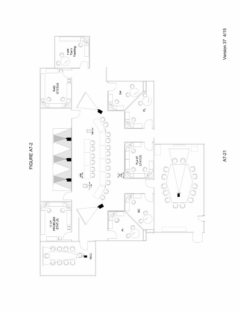
FIG
UR
E A
7-2
A7-
21
Ver
sion
37
4/1
5

APPENDIX 8
HATCH NUCLEAR PLANT
EMERGENCY ACTION LEVELS INITIATING CONDITIONS, THRESHOLD VALUES,
AND BASIS

TABLE OF CONTENTS
Section Title Page
A8-1 Version 37 4/15
1.0 Purpose ............................................................................................................................. A8-2
2.0 Background ....................................................................................................................... A8-3
3.0 Acronyms ........................................................................................................................... A8-5
4.0 Definitions .......................................................................................................................... A8-8
5.0 Mode Description ............................................................................................................. A8-15
6.0 Initiating conditions, Threshold Values & Basis ............................................................... A8-16
6.1 Category R – Abnormal Radiological ...................................................................... A8-17
6.2 Category F – Fission Product Barrier ...................................................................... A8-32
6.3 Category S – System Malfunctions – Hot Matrix ..................................................... A8-38
6.4 Category C – Cold Shutdown System Malfunctions ............................................... A8-61
6.5 Category E – ISFSI Events ..................................................................................... A8-80
6.6 Category H – Hazards and Others .......................................................................... A8-82

A8-2 Version 37 4/15
1.0 PURPOSE The purpose of this Appendix is to provide additional guidance and clarification to the EAL classification ICs matrices in Section D of this plan. They are utilized in the classification of off-normal events into one of four emergency classification levels. This Appendix provides the IC, TVs and Basis for each EAL grouped by their Recognition Categories. If after reviewing the classification IC matrices, the classification of an event or the determination if a TV is met or exceeded is unclear, the basis information provides additional clarification for each IC. There are three considerations related to emergency classes. These are: 1. The potential impact on radiological safety, either as now known or as can be
reasonably projected;
2. How far the plant is beyond its predefined design, safety, and operating envelopes; and
3. Whether or not conditions that threaten health are expected to be confined to within the site boundary.
Although the majority of the EALs provide very specific thresholds, the ED must remain alert to events or conditions that lead to the conclusion that exceeding the EAL threshold is imminent. If, in the judgment of the ED, an imminent situation is at hand, the classification should be made as if the threshold has been exceeded. While this is particularly prudent at the higher emergency classes (as the early classification may provide for more effective implementation of protective measures), it is nonetheless applicable to all emergency classes. At all times, when conditions present themselves that are not explicitly provided in the EAL scheme, the ED has discretion to declare an event based on his knowledge of the emergency classes and judgment of the situation or condition. Specific EALs (HU5, HA6, HS3, & HG2) are provided within the scheme to allow these discretionary classifications. The classification scheme is written to classify events based on meeting the IC and a TV for an EAL considering each unit independently. The IC matrices are human factored to read from top to bottom (i.e., General Emergency down to Notification of Unusual Event) within a category or subcategory to eliminate the higher classifications before reaching a lower classification. This arrangement lessens the possibility of under-classifying a condition. During events, the ICs and TVs are monitored, and if conditions meet another higher EAL, that higher emergency classification is declared and appropriate notifications are made. The notifications are made on a site basis, not a unit (1 or 2) basis. If both units are in concurrent classifications, the highest classification must be used for the notification and the other unit events noted on the SNC Emergency Notification form. The SNC policy is that once an emergency classification is made, it cannot be downgraded to a lower classification. Termination criteria contained in Procedure 73EP-EIP-002-0, Recovery, shall be completed for an event to be terminated. At termination, on an event-specific basis, the site can either enter normal operating conditions or enter a recovery condition with a recovery organization established for turnover from the ERO.

A8-3 Version 37 4/15
2.0 BACKGROUND HNP must respond to a formal set of threshold conditions that require plant personnel to take specific actions with regard to notifying State and local governments and the public when certain off-normal indicators or events are recognized. Emergency classes are defined in 10 CFR 50. The levels of response and conditions leading to those responses are defined in joint NRC/FEMA guidelines contained in Appendix 1 of NUREG-0654/FEMA-REP-1, Rev. 1, “Criteria for Preparation and Evaluation of Radiological Emergency Response Plans and Preparedness in Support of Nuclear Power Plants,” October 1980. The nuclear industry has developed NEI 99-01, Revision 4, a set of generic EAL guidelines and supporting basis, to use to develop the site-specific EALs, their TVs, and Basis. This generic guidance is intended to clearly define conditions that represent increasing risk to the public and can give consistent classifications when applied at different sites. It is a NRC endorsed acceptable alternative to the guidance in NUREG-0654. This information is presented by Recognition Category: R - Abnormal Rad Levels/Radiological Effluent
C - Cold Shutdown/Refueling System Malfunction
E - Events Related to Independent Spent Fuel Storage Installations (ISFSI)
F - Fission Product Barrier Degradation
H - Hazards and Other Conditions Affecting Plant Safety
S - System Malfunction In this appendix each of the EALs in Recognition Categories R, C, D, E, H, and S are structured in the following way: Recognition Category - As listed above.
Emergency Class - NUE, Alert, Site Area Emergency or General Emergency.
Initiating Condition - Symptom or Event-Based, Generic Identification and Title.
Operating Mode Applicability - Power Operation, Startup, Hot Shutdown, Cold Shutdown, Refueling, Defueled, or All.
TV(s) corresponding to the IC.
Basis information for plant-specific readings and factors that may relate to changing the generic IC or EAL to a different emergency class, such as for Loss of All AC Power.
For Recognition Category F, the EAL information is presented in a matrix format. The method was chosen to clearly show the synergism among the EALs and to support more accurate dynamic assessments. For category F, the EALs are arranged by fission product barrier. Classifications are based on various combinations of barrier challenges. Emergency classes were established by the NRC for grouping off-normal nuclear power plant conditions according to (1) their relative radiological seriousness, and (2) the time-sensitive onsite and offsite radiological emergency preparedness actions necessary to respond to such conditions. The existing radiological emergency classes, in ascending order of seriousness, are called: Notification of Unusual Event, Alert, Site Area Emergency, and General Emergency.

A8-4 Version 37 4/15
With the emergency classes defined, the ICs and TVs that must be met for each EAL to be placed under the emergency class can be determined. There are two basic approaches to determining these EALs. EALs and emergency class boundaries coincide for those continuously measurable, instrumented ICs such as radioactivity, core temperature, coolant levels, etc. For these ICs, the EAL will be the threshold reading that most closely corresponds to the emergency class description using the best available information. For discrete (discontinuous) events, the approach will have to be somewhat different. Typically, in this category are internal and external hazards such as fire or earthquake. The purpose for including hazards in EALs is to assure that station personnel and offsite emergency response organizations are prepared to deal with consequential damage these hazards may cause. If, indeed, hazards have caused damage to safety functions or fission product barriers, this should be confirmed by symptoms or by observation of such failures. Of course, security events must reflect potential for increasing security threat levels. The EALs and ICs can be grouped in one of several schemes. The classification scheme incorporates symptom-based, event-based, and barrier-based EALs and ICs. Symptom-based EALs and ICs refer to those indicators that are measurable over some continuous spectrum, such as core temperature, coolant levels, containment pressure, etc. The level of seriousness indicated by these symptoms depends on the degree to which they have exceeded technical specifications, the other symptoms or events that are occurring contemporaneously, and the capability of the licensed operators to gain control and bring the indicator back to safe levels. Event-based EALs and ICs refer to occurrences with potential safety significance, such as the failure of a high-pressure safety injection pump, a safety relief valve failure, or a loss of electric power to some part of the plant. The range of seriousness of these “events” is dependent on the location, number of contemporaneous events, remaining plant safety margin, etc. Several categories of emergencies have no instrumentation to indicate a developing problem, or the event may be identified before any other indications are recognized. For emergencies related to the reactor system and safety systems, the ICs shift to an event-based scheme as the plant mode moves toward cold shutdown and refueling modes. For nonradiological events, such as FIRE, floods, wind loads, etc., event-based ICs are the norm. Barrier-based EALs and ICs refer to the level of challenge to principal barriers used to assure containment of radioactive materials contained within a nuclear power plant. For radioactive materials that are contained within the reactor core, these barriers are: fuel cladding, reactor coolant system pressure boundary, and primary containment. The level of challenge to these barriers encompasses the extent of damage (loss or potential loss) and the number of barriers concurrently under challenge. The fission product barrier matrix is a hybrid approach that recognizes that some events may represent a challenge to more than one barrier, and that the containment barrier is weighted less than the reactor coolant system pressure boundary and the fuel clad barriers. The most common bases for establishing TVs are the technical specifications and setpoints for each plant that have been developed in the design basis calculations and the Final Safety Analysis Report (FSAR). For those conditions that are easily measurable and instrumented, the boundary is likely to be the EAL (observable by plant staff, instrument reading, alarm setpoint, etc.) that indicates entry into a particular emergency class. That radiation level also may be the setpoint that closes the main steam isolation valves (MSIV) and initiates the reactor scram. This same radiation level threshold, depending on plant-specific parameters, also may be the appropriate EAL for a direct entry into an emergency class.
A8-5 Version 37 4/15
3.0 Acronyms Acronyms, when used within an IC, TV or the basis, are defined within the body of the document. With this method, the user has a direct reference to the acronym’s usage without having to go to this section to determine its particular contextual meaning. Some exceptions exist for common nuclear power applications. In general the following list is provided for review purposes: µCi/gm Micro-Curie per gram
µCi/sec Micro-Curie per second
AC Alternating Current
AOP Abnormal Operating Procedure
ARI Alternate Rod Insertion
ARM Area Radiation Monitor, Alarm Response Manual
ATWS Anticipated Transient Without Scram
BWR Boiling Water Reactor
CAS Central Alarm Station
CDE Committed Dose Equivalent
CFR Code of Federal Regulations
CMT, CNMT, CTMT Containment
CO2 Carbon Dioxide
CPM Counts Per minute
CPS Counts Per second
CRD Control Rod Drive
DBE Design Basis Earthquake
DC Direct Current
DEI, DEI131 Dose equivalent Iodine 131
DW Drywell
DWRRM Drywell Wide Range Radiation Monitor
EAL Emergency Action Level
ECCS Emergency Core Cooling System
ECL Emergency Classification Level
ED Emergency Director
EDG Emergency Diesel Generator
ENN Emergency Notification Network
ENS Emergency Notification System
EOF Emergency Operations Facility
EOP Emergency Operating Procedure
EPA Environmental Protection Agency
EPIP, EIP Emergency Plan Implementing Procedure
ERG Emergency Response Guideline
ERO Emergency Response Organization
ESF Engineered Safeguards Feature

A8-6 Version 37 4/15
FAA Federal Aviation Administration
FBI Federal Bureau of Investigation
FEMA Federal Emergency Management Agency
FPB Fission Product Barrier
FSAR Final Safety Analysis Report
GE General Emergency, General Electric
GDC General Design Criteria
GPM Gallons per minute
HCTL Heat Capacity Temperature Limit
HNP Hatch Nuclear Plant
HPCI High Pressure Coolant Injection
H2 Hydrogen
IC Initiating Condition
ID Inside Diameter
IDLH Immediately Dangerous to Life and Health
IPEEE Individual Plant Examination of External Events (GL 88-20)
IRM Intermediate Range Monitor
ISFSI Independent Spent Fuel Storage Installation
LCO Limiting Condition of Operation
LER Licensee Event Report
LFL Lower Flammability Limit
LOCA Loss of Coolant Accident
LPSI Low Pressure Safety Injection
MCR Main Control Room
MSIV Main Steam Isolation Valve
MSL Main Steam Line
mR millirem
mR/hr millirem per hour
Mw Megawatt
NEI Nuclear Energy Institute
NORAD North American Aerospace Defense Command
NPP Nuclear Power Plant
NRC Nuclear Regulatory Commission
NOUE, NUE Notification of Unusual Event
OBE Operating Basis Earthquake
OCA Owner Controlled Area
ODCM Offsite Dose Calculation Manual
OPX Off Premise Extension
ORO Offsite Response Organization
O2 Oxygen
PA Protected Area
PAG Protective Action Guide

A8-7 Version 37 4/15
PAR Protective Action Recommendation
PBX Private Business Exchange
PRA/PSA Probabilistic Risk Assessment/Probabilistic Safety Assessment
PSIG Pounds per square inch Gauge
R/hr Rem per hour
R Rem
RAS Required Action Statement
RB Reactor Building
RECP Radiological Effluent Control Plan
RETS Radiological Effluent Technical Specification
RCIC Reactor Core Isolation Cooling
RCS Reactor Coolant System
RPS Reactor Protection System
RPV Reactor Pressure Vessel
RWL Reactor Water Level
Rx Reactor
SAE Site Area Emergency
SAS Secondary Alarm Station
SAT Startup Auxiliary Transformer
SBGTS Stand-By Gas Treatment System
SFP Spent Fuel Pool
SI Safety Injection
SM Shift Manager
SPDS Safety Parameter Display System
SRM Source Range Monitor
TEDE Total Effective Dose Equivalent
TOAF, TAF Top of Active Fuel
TS Technical Specification
TSC Technical Support Center
TV Threshold Value
VA Vital Area
VAC Volts Alternating Current
VDC Volts Direct Current
VOIP Voice Over Internet Protocol
A8-8 Version 37 4/15
4.0 DEFINITIONS
4.1 ALERT A condition where events are in process or have occurred which involve an actual or
potential substantial degradation of the level of safety of the plant. Any releases are expected to be limited to small fractions of the EPA Protective Action Guideline exposure levels. Discussion: Rather than discussing the distinguishing features of “potential degradation” and “potential substantial degradation,” a comparative approach would be to determine whether increased monitoring of plant functions is warranted at the Alert level as a result of safety system degradation. This addresses the operations staff’s need for help, independent of whether an actual decrease in plant safety is determined. This increased monitoring can then be used to better determine the actual plant safety state, whether escalation to a higher emergency class is warranted, or whether de-escalation or termination of the emergency class declaration is warranted. Dose consequences from these events are small fractions of the EPA PAG plume exposure levels, i.e., about 10 mR to 100 mR TEDE.
4.2 CIVIL DISTURBANCE An organized demonstration by an individual or group of unexpected, unidentified, or
unauthorized people within the Owner Controlled Area (OCA) which is used to promote a political or social issue or belief.
4.3 CLOSED WINDOW
A term indicating the position of the Beta radiation shield on a dose rate instrument or
its probe. It allows the instrument to read Gamma radiation only for use in measuring/estimating the DDE.
4.4 COMMITTED DOSE EQUIVALENT (CDE)
This term means the dose equivalent to organs or tissues of reference that will be
received from an intake of radioactive material by an individual during the 50-year period following the intake.
4.5 COMMITTED EFFECTIVE DOSE EQUIVALENT (CEDE)
The sum of the products of the weighting factors applicable to each of the body organs
or tissues that are irradiated and the committed dose equivalent to these organs or tissues.
4.6 CONFINEMENT BOUNDARY
The barrier(s) between areas containing radioactive substances and the environment.
This term is used in reference to ISFSI ICs. 4.7 CONTAINMENT INTEGRITY
The Primary Containment is OPERABLE per Technical Specification 3.6.1.1. The
Secondary Containment is OPERABLE per Technical Specification 3.6.4.1.

A8-9 Version 37 4/15
4.8 CONTAINMENT BARRIER
The Primary Containment Barrier includes the Drywell, the Torus, their respective interconnecting paths, and other connections up to and including the outermost containment isolation valves.
4.9 CREDIBLE THREAT
A threat is considered credible through use of 82SS-SEC-051-0, Threat Assessment. A
threat is credible when (1) physical evidence supporting the threat exists, or (2) information independent from the actual threat message exists that supports the threat, or (3) a specific group or organization claims responsibility for the threat, or (4) a message (written or verbal) is received that contains specific information about plant locations, systems, or device description an average person would most likely not know. The determination of credibility should be made by the Shift Manager with input from the Shift Captain or their designated representatives.
4.10 DEEP DOSE EQUIVALENT (DDE)
A term which applies to external whole body exposure, it is the dose equivalent at a
tissue depth of 1 cm. 4.11 EMERGENCY ACTION LEVEL (EAL)
A predetermined, site-specific, observable threshold for a plant IC that places the plant
in a given emergency class. An EAL can be: an instrument reading; an equipment status indicator; a measurable parameter (onsite or offsite); a discrete, observable event; results of analyses; entry into specific emergency operating procedures; or another phenomenon which, if it occurs, indicates entry into a particular emergency class. Discussion: There are times when an EAL will be a threshold point on a measurable continuous function, such as a primary system coolant leak that has exceeded technical specifications for a specific plant. At other times, the EAL and the IC will coincide, both identified by a discrete event that places the plant in a particular emergency class.
4.12 EXPLOSION
A rapid, violent, unconfined combustion or catastrophic failure of pressurized
equipment that imparts energy of sufficient force to potentially damage permanent structures, systems, or components.
4.13 FUEL CLAD BARRIER
The Fuel Clad Barrier is the zircalloy tubes that contain the fuel pellets. 4.14 FIRE
Combustion characterized by heat and light. Sources of smoke (i.e., slipping belts,
overheated electrical equipment) do not constitute FIREs. Observation of flame is preferred but NOT required if large quantities of smoke and heat are observed.

A8-10 Version 37 4/15
4.15 GENERAL EMERGENCY (GE)
A condition where events are in process or have occurred which involve actual or imminent substantial core degradation or melting with a potential for loss of CONTAINMENT INTEGRITY. Releases can be reasonably expected to exceed EPA PAG exposure levels offsite for more than the immediate site area. Discussion: The bottom line for the General Emergency is whether evacuation or sheltering of the general public is indicated based on EPA PAGs, and therefore should be interpreted to include radionuclide release regardless of cause. In addition, it should address concerns as to uncertainties in systems or structures (e.g., containment) response, and also events such as severe spent fuel pool events. To better assure timely notification, EALs in this category must primarily be expressed in terms of plant function status, with secondary reliance on dose projection. In terms of fission product barriers, loss of two barriers with loss or potential loss of the third barrier constitutes a General Emergency.
4.16 HOSTILE ACTION
An act toward an NPP or its personnel that includes the use of violent force to destroy
equipment, takes hostages, and /or intimidates the licensee to achieve an end. This includes attack by air, land, or water using guns, explosives, projectiles, vehicles, or other devices used to deliver destructive force. Other acts that satisfy the overall intent may be included. HOSTILE ACTION should not be construed to include acts of civil disobedience or felonious acts that are not part of a concerted attack on the NPP. Nonterrorism-based EALs should be used to address such activities, (e.g., violent acts between individuals in the owner-controlled area.)
4.17 HOSTILE FORCE
One or more individuals who are engaged in a determined assault, overtly or by stealth
and deception, equipped with suitable weapons capable of killing, maiming, or causing destruction.
4.18 IDENTIFIED leakage
Is defined as the measured leakage into the Drywell equipment drain system 4.19 IMMEDIATELY DANGEROUS TO LIFE AND HEALTH (IDLH)
A condition that either poses an immediate threat to life and health or an immediate
threat of severe exposure to contaminants which are likely to have adverse delayed effects on health.
4.20 IMMINENT
Mitigation actions have been ineffective, additional actions are not expected to be successful, and trended information indicates that the event or condition will occur.

A8-11 Version 37 4/15
4.21 IMPEDE
As used in this procedure, includes hindering or interfering provided that the interference or delay is sufficient to significantly threaten the safe operation of the plant.
4.22 INITIATING CONDITION (IC)
One of a predetermined subset of nuclear power plant conditions where either the
potential exists for a radiological emergency, or such an emergency has occurred. This term may be analogous to EAL is some cases. Discussion: Defined in this manner, an IC is an emergency condition which sets it apart from the broad class of conditions that may or may not have the potential to escalate into a radiological emergency. It can be a continuous, measurable function that is outside technical specifications, such as elevated RCS temperature or falling reactor coolant level (a symptom). It also encompasses occurrences such as FIRE (an event) or reactor coolant pipe failure (an event or a barrier breach).
4.23 LOWER FLAMMABILITY LIMIT (LFL)
The minimum concentration of a combustible substance that is capable of propagating
a flame through a homogenous mixture of the combustible and a gaseous oxidizer. 4.24 NORMAL PLANT OPERATIONS
Are activities at the plant site associated with routine testing, maintenance, or
equipment operations, in accordance with normal operating or administrative procedures. Entry into abnormal or emergency operating procedures, or deviation from normal security or radiological controls posture, is a departure from NORMAL PLANT OPERATIONS.
4.25 NOTIFICATION OF UNUSUAL EVENT (NUE)
A condition where events are in process or have occurred which indicates a potential
degradation of the level of safety of the plant. No releases of radioactive material requiring offsite response or monitoring are expected unless further degradation of safety systems occurs. Discussion: Potential degradation of the level of safety of the plant is indicated primarily by exceeding plant technical specification Limiting Condition of Operation (LCO) allowable action statement time for achieving required mode change. Precursors of more serious events should also be included because precursors do represent a potential degradation in the level of safety of the plant. Minor releases of radioactive materials are included. In this emergency class, however, releases do not require monitoring or offsite response (e.g., dose consequences of < 10 mR).
4.26 OWNER CONTROLLED AREA
The utility owned property around the plant where access is controlled during declared
emergencies by the plant security force.

A8-12 Version 37 4/15
4.27 PROTECTED AREA (PA)
The area which normally encompasses all controlled areas within the security protected area fence. The IFSFI “protected area” is not included in this general definition because it has a separate category for its ICs.
4.28 REACTOR COOLANT SYSTEM (RCS) BARRIER
The RCS Barrier is the reactor coolant system pressure boundary and includes the
reactor vessel and all reactor coolant system piping up to the isolation valves. 4.29 RECOGNITION CATEGORY
A term that describes the broad categories that the IC (i.e., EALs) have been divided
into to make the correct IC selection easier for the user. These categories have distinct letters associated with them which are used as the first letter of the IC.
These are: S – System Malfunction, H – Hazards and Other, F – Fission Product Barrier, R – Abnormal Radiation (Radiological), C – Cold Shutdown System Malfunctions, and E – ISFSI Events. 4.30 SECURITY CONDITION
Any security event as listed in the approved security contingency plan that constitutes a threat/compromise to site security, threat/risk to site personnel, or a potential degradation to the level of safety of the plant. A security condition does not involve a hostile action.
4.31 SIGNIFICANT TRANSIENT
An UNPLANNED event involving one or more of the following: (1) automatic runback
> 25% thermal reactor power, (2) electrical load rejection > 25% full electrical load, (3) Reactor Scram, (4) Safety System Injection Activation, or (5) thermal power oscillations > 10%.
4.32 SITE AREA EMERGENCY (SAE)
A condition where events are in process or have occurred which involve actual or likely
major failures of plant functions needed for protection of the public. Any releases are not expected to result in exposure levels which exceed EPA Protective Action Guideline exposure levels beyond the site boundary. Discussion: The discriminator (threshold) between Site Area Emergency and General Emergency is whether or not the EPA PAG plume exposure levels are expected to be exceeded outside the site boundary. This threshold, in addition to dynamic dose assessment considerations discussed in the EAL guidelines, clearly addresses NRC and offsite emergency response agency concerns as to timely declaration of a General Emergency.

A8-13 Version 37 4/15
4.33 STATION BLACKOUT
A complete loss of offsite and onsite AC power, as indicated by failure to energize any 4160-VAC Emergency bus.
4.34 STRIKE ACTION
A work stoppage within the PROTECTED AREA by a body of workers to enforce
compliance with demands. The STRIKE ACTION must threaten to interrupt NORMAL PLANT OPERATIONS.
4.35 SUBCRITICL
SUBCRITICAL: IRMs below Range 6 and Period is negative. Discussion: The
definition of SUBCRITICAL (IRMs below Range 6 and Period is negative) is the point at which the EOP guidance directs the operators to exit the EOPs and continue shutdown activities with normal plant procedures.
4.36 THRESHOLD VALUE (TV)
Is a predetermined, site-specific, observable threshold for a plant IC that places the
plant in a given emergency classification. A TV can be: an instrument reading; an equipment status indicator; a measurable parameter (onsite or offsite); a discrete, observable event; results of analyses; entry into specific emergency operating procedures; or another phenomenon which, if it occurs, indicates entry into a particular emergency class. This term is analogous to the term EAL in most cases.
4.37 TOTAL EFFECTIVE DOSE EQUIVALENT (TEDE)
Is a term that means the sum of the deep dose equivalent (for external exposures) and
the committed effective dose equivalent (for internal exposures). 4.38 UNIDENTIFIED leakage
Is defined as the measured leakage into the Drywell floor drain system 4.39 UNPLANNED
Is a parameter change or an event that is NOT the result of an intended evolution and
requires corrective or mitigative actions. This includes any release for which a radioactivity discharge permit was not prepared, or a release that exceeds the conditions (e.g., minimum dilution flow, maximum discharge flow, alarm setpoints, etc.) on the applicable permit.
4.40 VALID
An indication, report, or condition, is considered to be VALID when it is verified by (1)
an instrument channel check, or (2) indications on related or redundant indicators, or (3) by direct observation by plant personnel, such that doubt related to the indicator’s operability, the condition’s existence, or the report’s accuracy is removed. Implicit in this definition is the need for timely assessment.

A8-14 Version 37 4/15
4.41 VISIBLE DAMAGE
Is damage to equipment or structure that is readily observable without measurements, testing, or analysis. Damage is sufficient to cause concern regarding the continued operability or reliability of affected safety structure, system, or component. Example damage includes: deformation due to heat or impact, denting, penetration, rupture, cracking, paint blistering. Surface blemishes (e.g., paint chipping, scratches) should not be included.
4.42 VITAL AREA
Any area, normally within the PROTECTED AREA, which contains equipment,
systems, components, or material the failure, destruction, or release of which could directly or indirectly endanger the public health and safety by exposure to radiation. This includes the Control Building, Reactor Building, Diesel Generator Building, Intake Structure, and Primary containment.

A8-15 Version 37 4/15
5.0 MODE DESCRIPTION
Hatch Units 1 and 2 Technical Specifications Table 1.1-1 provides the following mode definitions:
Mode Title Reactor Mode Switch Position
Average RCS Temperature (oF)
1 Power Operation Run NA
2 Startup Refuel(a) or Startup/Hot Standby
NA
3 Hot Shutdown (a) Shutdown > 212
4 Cold Shutdown (a) Shutdown ≤ 212
5 Refueling (b) Shutdown or Refueling NA
(a) All reactor vessel head closure bolts fully tensioned.
(b) One or more reactor vessel head closure bolts less than fully tensioned
These modes are used throughout the Hatch EALs with no modifications from NEI 99-01. For the condition when a unit is defueled, the ICs designated as Mode Condition “ALL” or “Defueled” are applicable.

A8-16 Version 37 4/15
6.0
HNP EALS – INITIATING CONDITIONS, THRESHOLD VALUES AND BASIS

A8-17 Version 37 4/15
6.1 Category R - Abnormal Radiological

A8-18 Version 37 4/15
Initiating Condition RRGG11 Offsite Dose Resulting from an Actual or Imminent Release of Gaseous Radioactivity Exceeds 1000 mR TEDE OR 5000 mR Thyroid CDE for the Actual or Projected Duration of the Release Using Actual Meteorology.
Operating Mode Applicability: All
Threshold Values: (1 OR 2 OR 3)
NOTES: • If dose assessment results are available at the time of declaration, the classification should be based on TV #2 instead of TV #1. While necessary declarations should not be delayed awaiting results, the dose assessment should be initiated/completed in order to determine if the classification should be subsequently escalated.
• The ED should not wait until 15 minutes have elapsed, but should declare the event as soon as it is determined that the duration has or will likely exceed 15 minutes.
1. VALID reading on either of the following radiation monitors that exceeds or is expected to
exceed the reading shown for 15 minutes or longer:
Reactor Building Vent Accident Range Monitor – 1/2D11-P005 2.6 µCi/cc
Main Stack Accident Range Monitor- 1D11-P006 8.1 x 10³ µCi/cc
OR
2. Dose assessment using actual meteorology indicates doses greater than 1000 mR TEDE OR 5000 mR thyroid CDE at or beyond the site boundary.
OR
3. Field survey results indicate CLOSED WINDOW dose rates exceeding 1000 mR/hr expected to continue for more than 1 hour; OR analyses of field survey samples indicate thyroid CDE of 5000 mR for 1 hour of inhalation, at or beyond site boundary.

A8-19 Version 37 4/15
Basis: RRGG11
NOTE: The values used in TV# 1 are based on detailed calculations contained in calculation SMNH-05-009 Version 2.
CLOSED WINDOW: is a term indicating the position of the Beta radiation shield on a dose rate instrument or its probe. It allows the instrument to read Gamma radiation only for use in measuring/estimating the Deep Dose Equivalent (DDE). VALID: an indication, report, or condition is considered to be VALID when it is verified by (1) an instrument channel check, (2) indications on related or redundant indicators, or (3) by direct observation by plant personnel, such that doubt related to the indicator’s operability, the condition’s existence, or the report’s accuracy is removed. Implicit in this definition is the need for timely assessment. This IC addresses radioactivity releases that result in doses at or beyond the site boundary that exceed the EPA PAGs. Public protective actions will be necessary. Releases of this magnitude are associated with the failure of plant systems needed for the protection of the public and likely involve fuel damage. While these failures are addressed by other ICs, this IC provides appropriate diversity and addresses events which may not be able to be classified on the basis of plant status alone. The ED should not wait until 15 minutes have elapsed but should declare the event as soon as it is determined that the release duration has or will likely exceed 15 minutes. The monitor list in TV #1 includes monitors on potential release pathways. The monitor reading TVs are determined using a dose assessment method that back calculates from the dose values specified in the IC. The meteorology and source term used are the same as those used for determining the monitor reading TVs in ICs RU1 and RA1. Since doses are generally not monitored in real-time, a release duration of 1 hour is assumed, and that the TVs are based on a site boundary (or beyond) dose of 1000 mR/hour whole body or 5000 mR/hour thyroid, whichever is more limiting. Since dose assessment (Utilizing NMP-EP-104, Dose Assessment) is based on actual meteorology, whereas the monitor reading TVs are not, the results from these assessments may indicate that the classification is not warranted, or may indicate that a higher classification is warranted. For this reason, emergency implementing procedures call for the timely performance of dose assessments using actual meteorology and release information. If the results of these dose assessments are available when the classification is made, the dose assessment results override the monitor reading TVs. Classification should NOT be delayed pending the results of these dose assessments.

A8-20 Version 37 4/15
Initiating Condition RRSS11 Offsite Dose Resulting from an Actual or Imminent Release of Gaseous Radioactivity Exceeds 100 mR TEDE OR 500 mR Thyroid CDE for the Actual or Projected Duration of the Release.
Operating Mode Applicability: All
Threshold Values: (1 OR 2 OR 3)
NOTES: • If dose assessment results are available at the time of declaration, the classification should be based on TV #2 instead of TV #1. While necessary declarations should not be delayed awaiting results, the dose assessment should be initiated/completed in order to determine if the classification should be subsequently escalated.
• The ED should not wait until 15 minutes have elapsed, but should declare the event as soon as it is determined that the duration has or will likely exceed 15 minutes.
1. VALID reading on either of the following radiation monitors that exceeds or is expected to
exceed the reading shown for 15 minutes or longer:
Reactor Building Vent Accident Range Monitor – 1/2D11-P005 0.26 µCi/cc
Main Stack Accident Range Monitor - 1D11-P006 8.1 x 10² µCi/cc
OR
2. Dose assessment using actual meteorology indicates doses > 100 mR TEDE OR 500 mR thyroid CDE at or beyond the site boundary.
OR
3. Field survey results indicate CLOSED WINDOW dose rates > 100 mR/hr expected to continue for more than 1 hour; OR analyses of field survey samples indicate thyroid CDE of 500 mR for 1 hour of inhalation, at or beyond the site boundary.

A8-21 Version 37 4/15
Basis: RRSS11
NOTE: The values used in TV# 1 are based on detailed calculations contained in calculation SMNH-05-009 Version 2.
VALID: An indication, report, or condition, is considered to be VALID when it is verified by (1) an instrument channel check, (2) indications on related or redundant indicators, or (3) by direct observation by plant personnel such that doubt related to the indicator’s operability, the condition’s existence, or the report’s accuracy is removed. Implicit in this definition is the need for timely assessment. CLOSED WINDOW: is a term indicating the position of the Beta radiation shield on a dose rate instrument or its probe. It allows the instrument to read Gamma radiation only for use in measuring/estimating the DDE. This IC addresses radioactivity releases that result in doses at or beyond the site boundary that exceed a small fraction of the EPA PAGs. Releases of this magnitude are associated with the failure of plant systems needed for the protection of the public. While these failures are addressed by other ICs, this IC provides appropriate diversity and addresses events which may not be able to be classified on the basis of plant status alone. The ED should not wait until 15 minutes have elapsed, but should declare the event as soon as it is determined that the release duration has or will likely exceed 15 minutes. The monitor list in TV #1 includes monitors on potential release pathways. The monitor reading TVs are determined using a dose assessment method that back calculates from the dose values specified in the IC. The meteorology and source term used is the same as those used for determining the monitor reading TVs in ICs RU1 and RA1. Since doses are generally not monitored in real-time, a release duration of 1 hour is assumed and the TVs are based on a site boundary (or beyond) dose of 100 mR/hour whole body or 500 mR/hour thyroid, whichever is more limiting. Since dose assessment (Utilizing procedure NMP-EP-104, Dose Assessment) is based on actual meteorology, whereas the monitor reading TVs are not, the results from these assessments may indicate that the classification is not warranted or may indicate that a higher classification is warranted. For this reason, emergency implementing procedures call for the timely performance of dose assessments using actual meteorology and release information. If the results of these dose assessments are available when the classification is made, the dose assessment results override the monitor reading TVs. Classification should not be delayed pending the results of these dose assessments.

A8-22 Version 37 4/15
Initiating Condition RRAA11 Any UNPLANNED Release of Gaseous or Liquid Radioactivity to the Environment that Exceeds 200 Times the Radiological Effluent Technical Specifications for 15 Minutes or Longer.
Operating Mode Applicability: All
Threshold Values: (1 OR 2) .
NOTES: • The ED should not wait until 15 minutes have elapsed, but should declare the event as soon as it is determined that the duration has or will likely exceed 15 minutes.
1. VALID reading on any of the following effluent monitors that exceeds 200 times the alarm
setpoint established by a current radioactivity discharge permit for 15 minutes or longer.
Monitor
Liquid Radwaste Effluent Line Monitor – 1/2D11-K604
Service Water System Effluent Line Monitor - 1/2D11-K605
Reactor Building Vent Normal Range Monitor – 1D11-K619 A(B) & 2D11-K636 A(B)
Recombiner Building Vent Monitor – 1D11-R763 A(B)
Main Stack Normal Range Monitor - 1D11-K600 A(B)
OR
2. Confirmed sample analyses for gaseous or liquid releases indicates concentrations or release rates in excess of 200 times the values indicated in the Offsite Dose Calculation Manual (ODCM), with a release duration of 15 minutes or longer.

A8-23 Version 37 4/15
Basis: RRAA11 UNPLANNED: a parameter change or an event that is NOT the result of an intended evolution and requires corrective or mitigative actions. VALID: an indication, report, or condition is considered to be VALID when it is verified by (1) an instrument channel check, (2) indications on related or redundant indicators, or (3) by direct observation by plant personnel, such that doubt related to the indicator’s operability, the condition’s existence, or the report’s accuracy is removed. Implicit in this definition is the need for timely assessment. This IC addresses a potential or actual decline in the level of safety of the plant as indicated by a radiological release that exceeds regulatory commitments for an extended period of time. Nuclear power plants incorporate features intended to control the release of radioactive effluents to the environment. Administrative controls are established to prevent unintentional releases and to control and monitor intentional releases. These controls are located in the ODCM. The occurrence of extended, uncontrolled radioactive releases to the environment is indicative of degradation in these features and/or controls. The Radiological Effluent Control Program (RECP) multiples are specified in ICs RU1 and RA1 only to distinguish between nonemergency conditions and from each other. While these multiples obviously correspond to an offsite dose or dose rate, the emphasis in classifying these events is the degradation in the level of safety of the plant, NOT the magnitude of the associated dose or dose rate. Releases should not be prorated or averaged. UNPLANNED, as used in this context, includes any release for which a radioactivity discharge permit was not prepared, or a release that exceeds the conditions (e.g., minimum dilution flow, maximum discharge flow, alarm setpoints, etc.) on the applicable permit. The ED should not wait until 15 minutes have elapsed but should declare the event as soon as it is determined that the release duration has or will likely exceed 15 minutes. Also, if an ongoing release is detected and the starting time for that release is unknown, the ED should, in the absence of data to the contrary, assume that the release has exceeded 15 minutes. TV #1 addresses radioactivity releases that for whatever reason cause effluent radiation monitor readings that exceed 200 times the alarm setpoint established by the radioactivity discharge permit. This alarm setpoint may be associated with a planned batch release or a continuous release path. Indexing the TV to the ODCM setpoints in this manner ensures that the TV will never be less than the setpoint established by a specific discharge permit. Setpoints are 100 times those of RU1. TV # 2 addresses uncontrolled releases that are detected by sample analyses, particularly on unmonitored pathways, e.g., spills of radioactive liquids into storm drains, heat exchanger leakage in river water systems, etc. TVs #1 and #2 directly correlate with the IC since annual average meteorology is required to be used in showing compliance with the RECP and is used in calculating the alarm setpoints. The fundamental basis of this IC is NOT a dose or dose rate, but rather the degradation in the level of safety of the plant implied by the uncontrolled release.

A8-24 Version 37 4/15
Initiating Condition RRAA22 Damage to Irradiated Fuel OR Loss of Water Level that Has or Will Result in the Uncovering of Irradiated Fuel Outside the Reactor Vessel.
Operating Mode Applicability: All Threshold Values: (1 OR 2) 1. UNPLANNED VALID alarm on any of the following radiation monitors:
Refuel Floor Area Radiation Monitors:
• 1D21-K601 A - Rx Head Laydown Area
• 1D21-K601 D - Refuel Floor
• 1D21-K601 E - Drywell Shield Plug
• 1D21-K601 M - Spent Fuel Pool and New Fuel Storage area
• 2D21-K601 A - Rx Head Laydown Area
• 2D21-K601 M - Spent Fuel/Fuel Pool Areas
• 2D21-K601 E - Dryer/Separator Pool
• 2D21-K611 K - RPV Refuel Floor 228’
• 2D21-K611 L - RPV Refuel Floor 228’
Refuel Floor Ventilation Monitors:
• 1/2D11-K609 A-D - Rx Bldg. Potential Contaminate Area Vent Exhaust Rad Monitor
• 1/2D11-K611 A-D - Refuel Floor Vent Exhaust
• 2D11-K634 A-D - Refuel Floor Rx Well Vent. Exhaust
• 2D11-K635 A-D - Refuel Floor DW/Sep. Vent. Exhaust
OR
2. Loss of water level that has or will result in the uncovering of irradiated fuel outside the Reactor Vessel as indicated by ANY of the following:
Personnel report of irradiated fuel uncovered during fuel assembly movements.
Spent Fuel Pool - < 203’ elevation (Top of Fuel Racks)
Fuel Transfer Canal - < 218’ elevation (Top of Fuel Bundle in Transit)

A8-25 Version 37 4/15
Basis: RRAA22 UNPLANNED: a parameter change or an event that is not the result of an intended evolution and requires corrective or mitigative actions. VALID: an indication, report, or condition is considered to be VALID when it is verified by (1) an instrument channel check or (2) indications on related or redundant indicators, or (3) by direct observation by plant personnel, such that doubt related to the indicator’s operability, the condition’s existence, or the report’s accuracy is removed. Implicit in this definition is the need for timely assessment. This IC addresses specific events that have resulted or may result in unexpected rises in radiation dose rates within plant buildings and may be a precursor to a radioactivity release to the environment. These events represent a loss of control over radioactive material and represent degradation in the level of safety of the plant. TV #1 addresses radiation monitor indications of fuel uncovery and/or fuel damage. Raised readings on ventilation monitors may be indication of a radioactivity release from the fuel, confirming that damage has occurred. Raised background at the monitor due to water level lowering may mask raised ventilation exhaust airborne activity and needs to be considered. While a radiation monitor could detect a rise in dose rate due to a drop in the water level, it might not be a reliable indication of whether or not the fuel is covered. In TV #2, indications include water level and personnel reports. Visual observation will be the primary indicator for spent fuel pool and fuel movement activities. Personnel report of personnel during fuel assembly movements is included to ensure that reports of actual or potential fuel uncovery are classified. Depending on available level indication, the declaration threshold may need to be based on indications of water makeup rate or lowering in makeup tank level.

A8-26 Version 37 4/15
Initiating Condition RRAA33 Release of Radioactive Material or Rises in Radiation Levels Within the Facility That IMPEDES Operation of Systems Required to Maintain Safe Operations or to Establish or Maintain Cold Shutdown
Operating Mode Applicability: All Threshold Values: (1 OR 2) 1. VALID radiation readings greater than 15 mR/hr in areas requiring continuous occupancy to
maintain plant safety functions:
Control Room area radiation monitor 1D21-K600 B or C
Central Alarm Station (by survey)
OR
2. UNPLANNED VALID ARM readings greater than 1000 mR/hr in areas requiring infrequent access to maintain plant safety functions.
U1 Reactor Building as indicated by ARMs:
1D21-K601 C Spent Fuel Pool Demin Equipment 1D21-K601 F Tip Area 1D21-K601 G 130’ NE Working Area 1D21-K601 H 130’ SW Working Area 1D21-K601 K 158’ Working Area 1D21-K601 L Decant Pump and Equip Room 1D21-K601 N South CRD Hydraulic Units 1D21-K601 P North CRD Hydraulic Units 1D21-K601 R South Core Spray and RHR Area 1D21-K601 S Equipment Access Airlock 1D21-K601 T HPCI Turbine Area 1D21-K601 U Tip (Core) Probe Drive Area 1D21-K601 V RCIC Equipment Area SW 1D21-K601 W CRD Pump Room NW 1D21-K601 X RB 203’ Working Area 1D21-K601 Y North Core Spray and RHR Area
U2 Reactor Building as indicated by ARMs:
2D21-K601 B 158’ Level SE 2D21-K601 C 158’ Level NE 2D21-K601 D 158’ Level NW 2D21-K601 F Tip Area 2D21-K601 G 130’ NE Working Area 2D21-K601 H 130’ SW Working Area 2D21-K601 L Decant Pump & Equip Room 2D21-K601 N South CRD Hydraulic Units 2D21-K601 P Spent Fuel Pool Passageway 2D21-K601 R 185’ Level Operating Floor 2D21-K601 S 185’ Level Sample Panel 2D21-K601 T CRD Repair Area 2D21-K601 U 185’ Level RWCU Control Panel 2D21-K601 V RCIC Equipment Area 2D21-K601 W CRD Pump Room SW 2D21-K601 X RHR & Core Spray Room NE 2D21-K601 Y RHR & Core Spray Room SE

A8-27 Version 37 4/15
Basis: RRAA33 VALID: an indication, report, or condition is considered to be VALID when it is verified by (1) an instrument channel check, (2) indications on related or redundant indicators, or (3) by direct observation by plant personnel, such that doubt related to the indicator’s operability, the condition’s existence, or the report’s accuracy is removed. Implicit in this definition is the need for timely assessment. IMPEDE: As used here, includes hindering or interfering provided that the interference or delay is sufficient to significantly threaten the safe operation of the plant. This IC addresses raised radiation levels that impede necessary access to operating stations, or other areas containing equipment that must be operated manually or that requires local monitoring, in order to maintain safe operation or perform a safe shutdown. It is this impaired ability to operate the plant that results in the actual or potential substantial degradation of the level of safety of the plant. The cause and/or magnitude of the rise in radiation levels is not a concern of this IC. The ED must consider the source or cause of the raised radiation levels and determine if any other IC may be involved. This IC is not meant to apply to raises in the containment radiation monitors as these are events which are addressed in the fission product barrier matrix ICs. Nor is it intended to apply to anticipated temporary rises due to planned events (e.g., incore detector movement, Radwaste container movement, depleted resin transfers, etc.). The monitored area requiring continuous occupancy is the Control Room. The value of 15 mR/hr is derived from the GDC 19 value of 5 Rem in 30 days with adjustment for expected occupancy times. For areas requiring infrequent access, the 1000 mR/hr (Locked High Rad Area) is based on radiation levels which result in exposure control measures intended to maintain doses within normal occupational exposure guidelines and limits, and in doing so, will IMPEDE necessary access.

A8-28 Version 37 4/15
Initiating Condition RRUU11 Any UNPLANNED Release of Gaseous or Liquid Radioactivity to the Environment that Exceeds Two Times the Radiological Effluent Technical Specifications for 60 Minutes or Longer.
Operating Mode Applicability: All
Threshold Values: (1 OR 2)
NOTE: • The ED should not wait until 60 minutes have elapsed, but should declare the event as soon as it is determined that the duration has or will likely exceed 60 minutes.
1. VALID reading on any of the following effluent monitors that exceeds two times the alarm
setpoint established by a current radioactivity discharge permit for 60 minutes or longer.
Monitor
Liquid Radwaste Effluent Line Monitor – 1/2D11-K604
Service Water System Effluent Line Monitor - 1/2D11-K605
Reactor Building Vent Normal Range Monitor – 1D11-K619 A(B) & 2D11-K636 A(B)
Recombiner Building Vent Monitor – 1D11-R763 A(B)
Main Stack Normal Range Monitor- 1D11-K600 A(B)
OR
2. Confirmed sample analyses for UNPLANNED gaseous or liquid releases indicates concentrations with a release duration of 60 minutes or longer, in excess of two times Technical Specification 5.5.4 as confirmed by Offsite Dose Calculation Manual (ODCM).

A8-29 Version 37 4/15
Basis: RRUU11
VALID: an indication, report, or condition, is considered to be VALID when it is verified by (1) an instrument channel check, or (2) indications on related or redundant indicators, or (3) by direct observation by plant personnel, such that doubt related to the indicator’s operability, the condition’s existence, or the report’s accuracy is removed. Implicit in this definition is the need for timely assessment.
UNPLANNED: a parameter change or an event that is not the result of an intended evolution and requires corrective or mitigative actions. As used in this context, UNPLANNED includes any release for which a radioactivity discharge permit was not prepared, or a release that exceeds the conditions (e.g., minimum dilution flow, maximum discharge flow, alarm setpoints, etc.) on the applicable permit. The ED should not wait until 60 minutes have elapsed, but should declare the event as soon as it is determined that the release duration has or will likely exceed 60 minutes. Also, if an ongoing release is detected and the starting time for that release is unknown, the ED should, in the absence of data to the contrary, assume that the release has exceeded 60 minutes.
This IC addresses a potential or actual decline in the level of safety of the plant as indicated by a radiological release that exceeds regulatory commitments for an extended period of time. Administrative controls are established to prevent unintentional releases, or control and monitor intentional releases. These controls are located in the ODCM. The occurrence of extended, uncontrolled radioactive releases to the environment is indicative of degradation in these features and/or controls.
TV #1 addresses radioactivity releases that, for whatever reason, cause effluent radiation monitor readings to exceed two times the Technical Specification limit and releases are not terminated within 60 minutes. This alarm setpoint may be associated with a planned batch release or a continuous release path. In either case, the setpoint is established by the ODCM to warn of a release that is not in compliance with the Tech Spec 5.5.4. Indexing the TV to the ODCM setpoints in this manner ensures that the TV will never be less than the setpoint established by a specific discharge permit. Sixty minutes is used because it signifies a degradation in the level of plant safety because of the ongoing release vs. a single discharge over the ODCM limits which have terminated.
TV 2 addresses UNPLANNED uncontrolled releases that are detected by sample analyses, particularly on unmonitored pathways, e.g., spills of radioactive liquids into storm drains, heat exchanger leakage in river water systems, etc.
Thresholds #1 and #2 directly correlate with the IC since annual average meteorology is required to be used in showing compliance with the TS 5.5.4 and is used in calculating the alarm setpoints. However, the fundamental basis of this IC is NOT a dose or dose rate, but rather the degradation in the level of safety of the plant implied by the uncontrolled release.

A8-30 Version 37 4/15
Initiating Condition RRUU22 Unexpected Rise in Plant Radiation.
Operating Mode Applicability: All Threshold Values: [(1.a AND 1.b.) OR 2] 1. a. VALID indication of uncontrolled water level lowering in the reactor refueling cavity,
spent fuel pool (SFP) or fuel transfer canal with all irradiated fuel assemblies remaining covered by water as indicated by any of the following:
Personnel report of low water level
SFP low level alarm annunciator - Spent Fuel Storage Pool Level Low 654-022-1/2
AND
b. UNPLANNED VALID Area Radiation Monitor (ARM) reading rise on any of the following:
1D21-K601 A - Rx Head Laydown Area
1D11-K601 D - Refuel Floor
1D21-K601 E –Drywell Shield Plug
1D21-K601 M - Spent Fuel Pool and New Fuel Storage area
2D21-K601 A - Rx Head Laydown Area
2D21-K601 M – Spent Fuel/Fuel Pool Areas
2D21-K601 E - Dryer/Separator Pool
2D21-K611 K – RPV Refuel Floor 228’
2D21-K611 L – RPV Refuel Floor 228’
OR
NOTE: • Normal levels can be considered as the highest reading in the past 24 hours excluding the current peak value.
2. UNPLANNED VALID ARM readings rise by a factor of 1000 over normal levels.

A8-31 Version 37 4/15
Basis: RRUU22 UNPLANNED: a parameter change or an event that is not the result of an intended evolution and requires corrective or mitigative actions. VALID: an indication, report, or condition is considered to be VALID when it is verified by (1) an instrument channel check, or (2) indications on related or redundant indicators, or (3) by direct observation by plant personnel, such that doubt related to the indicator’s operability, the condition’s existence, or the report’s accuracy is removed. Implicit in this definition is the need for timely assessment. This IC addresses raised radiation levels as a result of water level lowering above the RPV flange or events that have resulted, or may result, in unexpected rises in radiation dose rates within plant buildings. These radiation rises represent a loss of control over radioactive material and may represent a potential degradation in the level of safety of the plant. Threshold 1a limits: Personnel report of low water level is the primary indicator. While other radiation monitors could detect a rise in dose rate due to a drop in the water level, it might not be a reliable indication of whether or not the fuel is covered. Increased radiation monitor indications will need to be combined with another indicator (or personnel report) of water loss. TV #2 addresses UNPLANNED rises in in-plant radiation levels that represent a degradation in the control of radioactive material and a potential degradation in the level of safety of the plant.

A8-32 Version 37 4/15
6.2 Category F - Fission Product Barrier

A8-33 Version 37 4/15
Fission Product Barrier Evaluation GENERAL EMERGENCY Initiating Condition FG1 - Loss of ANY Two Barriers AND Loss or Potential Loss of Third Barrier SITE AREA EMERGENCY Initiating Condition FS1 - Loss or Potential Loss of ANY Two Barriers ALERT Initiating Condition
FA1 - ANY Loss or ANY Potential Loss of EITHER Fuel Clad OR RCS BarrierA1 UNUSUAL EVENT Initiating Condition FU1 - ANY Loss or ANY Potential Loss of Containment Barrier Operating Mode Applicability: Power Operation (Mode 1) Startup (Mode 2) Hot Shutdown (Mode 3)
FUEL CLAD BARRIER THRESHOLD VALUES The Fuel Clad barrier is the zircalloy tubes that contain the fuel pellets. 1. Primary Coolant Activity Level The “Loss” value 300 µCi/gm DEI131 RCS activity corresponds to 300 μCi/gm I131 equivalent. Assessment indicates that this amount of coolant activity is well above that expected for iodine spikes and corresponds to < 5% fuel clad damage. This amount of radioactivity indicates significant clad damage, and thus, the Fuel Clad Barrier is considered lost. There is no “Potential Loss” Threshold associated with this item. 2. Reactor Vessel Water Level The “Loss” Threshold (< -193 inches) is the minimum value to assure core cooling without further degradation of the clad. This value corresponds to 2/3 coverage of active fuel. The “Potential Loss” Threshold (< -155 inches) is the same as the RCS barrier “Loss” Threshold #2 below and is -155 inches which is used in the EOPs for operator actions. Thus, this Threshold indicates a “Loss” of RCS barrier and a “Potential Loss” of the Fuel Clad Barrier. This Threshold appropriately escalates the emergency class to a Site Area Emergency.

A8-34 Version 37 4/15
3. Drywell Radiation Monitoring The 1400 R/hr DWRRM reading is a value which indicates the release of Reactor coolant, with elevated activity indicative of fuel damage, into the Drywell. The reading should be calculated assuming the instantaneous release and dispersal of the reactor coolant noble gas and iodine inventory associated with a concentration of 300 μCi/gm dose equivalent I131 or the calculated concentration equivalent to the clad damage used in Threshold #1 into the drywell atmosphere. Reactor coolant concentrations of this magnitude are several times larger than the maximum concentrations (including iodine spiking) allowed within technical specifications and are therefore indicative of fuel damage. This value is higher than that specified for RCS barrier Loss Threshold #4. Thus, this Threshold indicates a loss of both Fuel Clad barrier and RCS barrier. There is no “Potential Loss” Threshold associated with this item. 4. Other Indications Offgas pre- and post-treatment monitors Offscale High and Drywell Fission Products Monitor Offscale High detect the effluent of the Offgas system and therefore indicate fission products escaping the clad. There is no “Potential Loss” Threshold associated with this item. 5. Emergency Director Judgment This Threshold addresses any other factors that are to be used by the ED in determining whether the Fuel Clad barrier is lost or potentially lost. In addition, the inability to monitor the barrier should also be incorporated in this Threshold as a factor in ED’s judgment that the barrier may be considered lost or potentially lost. (See also IC# SG1, “Prolonged Loss of All Offsite Power and Prolonged Loss of All Onsite AC Power,” for additional information.)
RCS BARRIER THRESHOLD VALUES
The RCS Barrier is the reactor coolant system pressure boundary and includes the reactor vessel and all reactor coolant system piping up to the isolation valves. 1. Drywell Pressure The 1.85 psig drywell pressure is based on the drywell high pressure setpoint which indicates a LOCA by automatically initiating the ECCS or equivalent makeup system. Pressure increases requiring containment venting for temperature or pressure (i.e., loss of chillers, Drywell Nitrogen fill event, etc.) when not in an accident situation should not be considered. There is no “Potential Loss” Threshold associated with this item.

A8-35 Version 37 4/15
2. Reactor Vessel Water Level This “Loss” Threshold is the same as “Potential Loss” Fuel Clad Barrier Threshold #2. The -155” water level corresponds to the level which is used in EOPs to indicate challenge of core cooling. This Threshold appropriately escalates the emergency class to a Site Area Emergency. Thus, this Threshold indicates a loss of the RCS barrier and a Potential Loss of the Fuel Clad Barrier. There is no “Potential Loss” Threshold associated with this item. 3. RCS Leak Rate An unisolable MSL break is a breach of the RCS barrier. Thus, this Threshold is included for consistency with the Alert emergency classification. The potential loss of RCS based on leakage is set at a level indicative of a small breach of the RCS but which is well within the makeup capability of normal and emergency high pressure systems. Core uncovery is not a significant concern for a 50-gpm leak; however, break propagation leading to significantly larger loss of inventory is possible. Potential loss of RCS based on primary system leakage outside the drywell is determined from temperature or area radiation alarms setpoint in the areas of the main steam line tunnel, main turbine generator, RCIC, HPCI, etc., which indicate a direct path from the RCS to areas outside primary containment. The indicators should be confirmed to be caused by RCS leakage. The area temperature or radiation alarm setpoints are indicated for this example to enable an Alert classification. 4. Drywell Radiation Monitoring The 40 R/hr reading is a value which indicates the release of reactor coolant to the drywell. The reading was calculated assuming the instantaneous release and dispersal of the reactor coolant noble gas and iodine inventory associated with normal operating concentrations (i.e., within T/S) into the drywell atmosphere. This reading will be less than that specified for Fuel Clad Barrier Threshold #3. Thus, this Threshold would be indicative of a RCS leak only. There is no “Potential Loss” Threshold associated with this item. 5. Other (Site-Specific) Indications For the Loss, Drywell Fission Products Monitor 5.0E5 cpm indicates a breach of the RCS as an effluent. (The monitor value calculated in calculation SMNH-05-009 Version 2 was 1.008E6 cpm; however, top of scale for this monitor is 1E6. Therefore, the EAL setpoint has been established at one half decade below top of scale to aid the operator in distinguishing between a loss of RCS event and an instrument failure resulting in the monitor reading high off scale.) No radiation monitors capable of indicating a potential loss of the RCS barrier were identified. There is no “Potential Loss” Threshold associated with this item.

A8-36 Version 37 4/15
6. Emergency Director Judgment This Threshold addresses any other factors that are to be used by the ED in determining whether the RCS barrier is lost or potentially lost. In addition, the inability to monitor the barrier should also be incorporated in this Threshold as a factor in ED’s judgment that the barrier may be considered lost or potentially lost. (See also IC SG1, “Prolonged Loss of Offsite Power and Prolonged Loss of All Onsite AC Power,” for additional information.)

A8-37 Version 37 4/15
PRIMARY CONTAINMENT BARRIER THRESHOLD VALUES The Primary Containment Barrier includes the Drywell, the Torus, their respective interconnecting paths, and other connections up to and including the outermost containment isolation valves. Containment Barrier Thresholds are used primarily as discriminators for escalation from an Alert to a Site Area Emergency or a General Emergency. 1. Drywell Pressure CONTAINMENT INTEGRITY: Primary Containment OPERABLE per Technical Specification 3.6.1.1. Secondary Containment OPERABLE per Technical Specification 3.6.4.1. Rapid unexplained loss of pressure (i.e., not attributable to Containment spray or condensation effects) following an initial pressure increase indicates a loss of Primary CONTAINMENT INTEGRITY. Drywell pressure should rise as a result of mass and energy release into containment from a LOCA. Thus, drywell pressure not rising under these conditions indicates a loss of Primary CONTAINMENT INTEGRITY. This indicator relies on the operator’s recognition of an unexpected response for the condition and therefore does not have a specific value associated. The unexpected response is important because it is the indicator for a containment bypass condition. The 56 psig for potential loss of containment is based on the containment drywell design pressure. Existence of an explosive mixture means a Hydrogen and Oxygen concentration of at least the lower deflagration limit curve exists. Explosive mixture inside containment ≥ 6% Hydrogen and ≥ 5% Oxygen.
2. Reactor Vessel Water Level There is no “Loss” Threshold associated with this item. The entry into the Primary Containment Flooding emergency procedure indicates reactor vessel water level cannot be restored and that a core melt sequence is in progress. EOPs direct the operators to enter Containment Flooding when Reactor Vessel Level cannot be restored to greater than 2/3 core height or is unknown. Entry into Containment Flooding procedures is a logical escalation in response to the inability to maintain reactor vessel level. The conditions in this potential loss Threshold represents imminent core melt sequences which, if not corrected, could lead to vessel failure and increased potential for containment failure. If the emergency operating procedures have been ineffective in restoring reactor vessel level above the RCS and Fuel Clad Barrier TVs, there is not a “success” path and a core melt sequence is in progress. Entry into Containment flooding procedures is a logical escalation in response to the inability to maintain reactor vessel level. Severe accident analysis (e.g., NUREG-1150) has concluded that function restoration procedures can arrest core degradation with the reactor vessel in a significant fraction of the core damage scenarios, and the likelihood of containment failure is very small in these events. Given this, it is appropriate to provide a reasonable period to allow emergency operating procedures to arrest the core melt sequence. Whether or not the procedures will be effective should be apparent within the time provided. The ED should make the declaration as soon as it is determined that the procedures have been, or will be, ineffective.

A8-38 Version 37 4/15
3. Containment Isolation Failure or Bypass This Threshold is intended to cover the inability to isolate the containment when containment isolation is required. In addition, the presence of area radiation or temperature alarms high setpoint indicating unisolable primary system leakage outside the drywell are covered after a containment isolation. The indicators should be confirmed to be caused by RCS leakage. Also, an intentional venting of primary containment for pressure control per EOPs to the secondary containment and/or the environment is considered a loss of containment. Containment venting for temperature or pressure when not in an accident situation (i.e., loss of chillers, Drywell Nitrogen fill event, etc.) should not be considered. There is no “Potential Loss” Threshold associated with this item. 4. Significant Radioactive Inventory in Containment
NOTE: TV#4 is based on detailed calculations contained in SMNH-05-009 Version 2.
There is no “Loss” Threshold associated with this item. The -2.6E4 R/hr DWRRM reading is a value which indicates significant fuel damage well in excess of that required for loss of RCS and Fuel Clad. A major release of radioactivity requiring offsite protective actions from core damage is not possible unless a major failure of fuel cladding allows radioactive material to be released from the core into the reactor coolant. Regardless of whether containment is challenged, this amount of activity in containment, if released, could have such severe consequences that it is prudent to treat this as a potential loss of containment, such that a General Emergency declaration is warranted. Such conditions do not exist when the amount of clad damage is < 20%. 6. Emergency Director Judgment This Threshold addresses any other factors that are to be used by the ED in determining whether the Containment barrier is lost or potentially lost. In addition, the inability to monitor the barrier should also be incorporated in this Threshold as a factor in ED’s judgment that the barrier may be considered lost or potentially lost. (See also IC SG1, “Prolonged Loss of All Offsite Power and Prolonged Loss of All Onsite AC Power,” for additional information.)

A8-39 Version 37 4/15
6.3 Category S - System Malfunctions - Hot Matrix
A8-40 Version 37 4/15
Initiating Condition SSGG11 Prolonged Loss of All Offsite Power AND Prolonged Loss of All Onsite AC Power to Essential Busses.
Operating Mode Applicability: Power Operation (Mode 1) Startup (Mode 2) Hot Shutdown (Mode 3) Threshold Value: [(1.a AND 1.b.) AND (2 OR 3)] 1. Loss of all AC power indicated by:
a. Loss of power to or from Startup Auxiliary Transformers (SAT) 1/2C and 1/2D resulting in loss of all off-site electrical power to 4160 VAC Emergency Busses 1/2E, 1/2F, and 1/2G for > 15 minutes
AND
b. Failure of emergency diesel generators to supply power to emergency busses.
AND EITHER
2. Restoration of at least one 4160-VAC Emergency Bus, 1/2E, 1/2F, or 1/2G within 4 hours of time of loss is NOT likely.
OR
3. Fuel Clad Barrier Evaluation indicates continuing degradation (Loss OR Potential Loss) of core cooling.
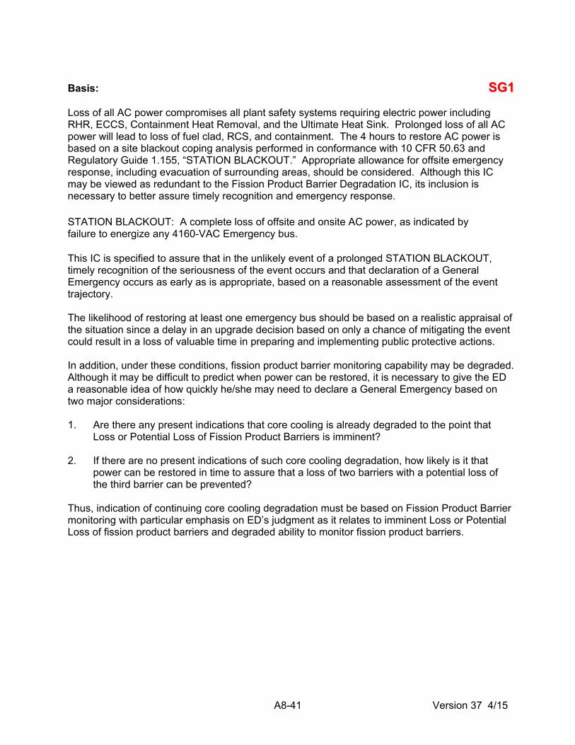
A8-41 Version 37 4/15
Basis: SSGG11 Loss of all AC power compromises all plant safety systems requiring electric power including RHR, ECCS, Containment Heat Removal, and the Ultimate Heat Sink. Prolonged loss of all AC power will lead to loss of fuel clad, RCS, and containment. The 4 hours to restore AC power is based on a site blackout coping analysis performed in conformance with 10 CFR 50.63 and Regulatory Guide 1.155, “STATION BLACKOUT.” Appropriate allowance for offsite emergency response, including evacuation of surrounding areas, should be considered. Although this IC may be viewed as redundant to the Fission Product Barrier Degradation IC, its inclusion is necessary to better assure timely recognition and emergency response. STATION BLACKOUT: A complete loss of offsite and onsite AC power, as indicated by failure to energize any 4160-VAC Emergency bus. This IC is specified to assure that in the unlikely event of a prolonged STATION BLACKOUT, timely recognition of the seriousness of the event occurs and that declaration of a General Emergency occurs as early as is appropriate, based on a reasonable assessment of the event trajectory. The likelihood of restoring at least one emergency bus should be based on a realistic appraisal of the situation since a delay in an upgrade decision based on only a chance of mitigating the event could result in a loss of valuable time in preparing and implementing public protective actions. In addition, under these conditions, fission product barrier monitoring capability may be degraded. Although it may be difficult to predict when power can be restored, it is necessary to give the ED a reasonable idea of how quickly he/she may need to declare a General Emergency based on two major considerations: 1. Are there any present indications that core cooling is already degraded to the point that
Loss or Potential Loss of Fission Product Barriers is imminent? 2. If there are no present indications of such core cooling degradation, how likely is it that
power can be restored in time to assure that a loss of two barriers with a potential loss of the third barrier can be prevented?
Thus, indication of continuing core cooling degradation must be based on Fission Product Barrier monitoring with particular emphasis on ED’s judgment as it relates to imminent Loss or Potential Loss of fission product barriers and degraded ability to monitor fission product barriers.

A8-42 Version 37 4/15
Initiating Condition SSGG22 Failure of the Reactor Protection System to Complete an Automatic Scram AND Manual Scram was NOT Successful AND there is Indication of an Extreme Challenge to the Ability to Cool the Core.
Operating Mode Applicability: Power Operation (Mode 1) Startup (Mode 2) Threshold Value: [(1.a. AND 1.b.) AND (2.a. OR 2.b.)] 1. Indications exist that a reactor protection system setpoint was exceeded and automatic
scram did not occur and a manual scram did not result in the reactor being made SUBCRITICAL (IRMs below Range 6 and Period is negative).
AND
2. EITHER of the following:
a. Core cooling is severely challenged as indicated by inability to restore and maintain Reactor Water Level > -185” on the affected unit.
OR
b. Heat removal is extremely challenged as indicated by Exceeding the Heat Capacity Temperature Limit (HCTL) Curve (EOP Graph 2).

A8-43 Version 37 4/15
Basis: SSGG22 SUBCRITICAL: IRMs below Range 6 and Period is negative. Automatic and manual SCRAM are NOT considered successful if action away from the reactor control console (1/2H11-P603 Panel) is required to SCRAM the reactor. Under the conditions of this IC and its associated TVs, the efforts to bring the reactor subcritical have been unsuccessful and, as a result, the reactor is producing more heat than the maximum decay heat load for which the safety systems were designed. Although there are capabilities, such as standby liquid control, the continuing temperature rise indicates that these capabilities are not effective. This situation could be a precursor for a core melt sequence. The extreme challenge to the ability to cool the core is intended to mean that the reactor vessel water level cannot be restored and maintained above Minimum Steam Cooling RPV Water Level (-185”) as described in the EOP bases. Another consideration is the inability to initially remove heat during the early stages of this sequence. Considerations include inability to remove heat via the main condenser, or via the torus (e.g., due to high water temperature). In the event either of these challenges exist at a time that the reactor has not been brought below the power associated with the safety system design (5% power) a core melt sequence exists. In this situation, core degradation can occur rapidly. For this reason, the General Emergency declaration is intended to be anticipatory of the fission product barrier matrix declaration to permit maximum offsite intervention time. The Reactor should be considered SUBCRITICAL when IRMs below Range 6 and Period is negative. A failure of the RPS to shut down the reactor (as indicated by reactor NOT being SUBCRITICAL) is a degraded plant condition that may require the injection of boron to shut down the reactor per EOP guidance. The definition of SUBCRITICAL (IRMs below Range 6 and Period is negative) is the point at which the EOP guidance directs the operators to exit the EOPs and continue shutdown activities with normal plant procedures.

A8-44 Version 37 4/15
Initiating Condition SSSS11 Loss of All Offsite Power AND Loss of All Onsite AC Power to Essential Busses.
Operating Mode Applicability: Power Operation (Mode 1) Startup (Mode 2) Hot Shutdown (Mode 3) Threshold Value: (1.a AND 1.b AND 1.c) 1. Loss of all AC power indicated by: a. Loss of power to or from Startup Auxiliary Transformers (SAT) 1/2C and 1/2D resulting in
loss of all off-site electrical power to 4160-VAC Emergency Busses 1/2E, 1/2F, and 1/2G for > 15 minutes
AND
b. Failure of emergency diesel generators to supply power to emergency busses
AND
c. Restoration of at least one 4160-VAC Emergency bus, 1/2E, 1/2F, or 1/2G has NOT occurred within 15 minutes of time of loss of all AC power
Basis: CONTAINMENT INTEGRITY: Primary Containment OPERABLE per Technical Specification 3.6.1.1. Secondary Containment OPERABLE per Technical Specification 3.6.4.1. Loss of all AC power compromises all plant safety systems requiring electric power including RHR, ECCS, Containment Heat Removal, and the Ultimate Heat Sink. Prolonged loss of all AC power will cause core uncovering and loss of CONTAINMENT INTEGRITY, thus this event can escalate to a General Emergency. The 15-minute time duration is to exclude transient or momentary power losses. Consideration should be given to operable loads necessary to remove decay heat or provide Reactor Vessel makeup capability when evaluating loss of AC power to emergency busses. Even though an emergency bus may be energized, if necessary loads (i.e., loads that if lost would inhibit decay heat removal capability or Reactor Vessel makeup capability) are not operable on the energized bus, then the bus should not be considered operable.

A8-45 Version 37 4/15
Initiating Condition SSSS22
Failure of Reactor Protection System Instrumentation to Complete or Initiate an Automatic Reactor Scram Once a Reactor Protection System Setpoint Has Been Exceeded AND Manual Scram Was NOT Successful.
Operating Mode Applicability: Power Operation (Mode 1) Startup (Mode 2) Threshold Value:
1. Indications exist that a reactor protection system setpoint was exceeded
AND
Automatic scram did NOT occur,
AND
A manual scram did NOT result in the reactor being made SUBCRITICAL (IRMs below Range 6 and Period is negative).
Basis:
SUBCRITICAL: IRMs below Range 6 and Period is negative
Automatic and manual scram are not considered successful if action away from the reactor control console (1/2H11-P603 Panel) was required to scram the reactor.
This TV is not applicable if no RPS setpoints are exceeded prior to initiating a successful manual scram. RPS setpoints may be exceeded following a successful SCRAM when the mode switch is taken to the shutdown position. This may cause an RPS setpoint to be exceeded due to the change in Nuclear Instrumentation Scram setpoint when the mode switch is taken out of the Run position. If the RPS then fails to initiate a scram, then this should be evaluated as an automatic RPS setpoint being exceeded.
The RPS is designed to function to shut down the reactor. The system is “fail safe,” in that it de-energizes to function. An Anticipated Transient Without Scram (ATWS) event results from either a failure of RPS (electrical failure) or the Control Rod Drive system to permit the control rods to insert. The Reactor should be considered SUBCRITICAL when IRMs below Range 6 and Period is negative. A failure of the RPS to shut down the reactor (as indicated by reactor NOT being SUBCRITICAL) is a degraded plant condition that may require the injection of boron to shut down the reactor per EOP guidance. The definition of SUBCRITICAL IRMs below Range 6 and Period is negative is the point at which the EOP guidance directs the operators to exit the EOPs and continue shutdown activities with normal plant procedures. Under these continued power operation conditions, the reactor may be producing more heat than the maximum decay heat load for which the safety systems are designed. A Site Area Emergency is indicated because conditions exist that may lead to imminent loss or potential loss of both fuel clad and RCS. Although this IC may be viewed as redundant to the Fission Product Barrier Degradation IC, its inclusion is necessary to better assure timely recognition and emergency response. Escalation of this event to a General Emergency would be via Fission Product Barrier Degradation or ED Judgment ICs.

A8-46 Version 37 4/15
Initiating Condition SSSS33 Loss of All Vital DC Power.
Operating Mode Applicability: Power Operation (Mode 1) Startup (Mode 2) Hot Shutdown (Mode 3) Threshold Value: 1. Loss of DC power to 125/250-VDC Bus 1/2R22-S016 and 1/2R22-S017 indicated by bus
voltage indications < 105/210 VDC for > 15 minutes. Basis: CONTAINMENT INTEGRITY: Primary Containment OPERABLE per Technical Specification 3.6.1.1. Secondary Containment OPERABLE per Technical Specification 3.6.4.1. Loss of DC power compromises ability to monitor and control plant safety functions. Prolonged loss of all DC power will cause core uncovering and loss of CONTAINMENT INTEGRITY when there is significant decay heat and sensible heat in the reactor system. 105/210-VDC bus voltage is based on the minimum bus voltage necessary for the operation of safety related equipment. Fifteen minutes was selected as a threshold to exclude transient or momentary power losses.

A8-47 Version 37 4/15
Initiating Condition SSSS44 Complete Loss of Heat Removal Capability.
Operating Mode Applicability: Power Operation (Mode 1) Startup (Mode 2) Hot Shutdown (Mode 3) Threshold Value: 1. Heat Capacity Temperature Limit (HCTL) Curve (EOP Graph 2) CANNOT be maintained in
the “Safe” region. Basis: This TV addresses a severe challenge to Primary Containment at pressure and temperature. Under these conditions, there is an actual major failure of a system intended for protection of the public. Thus, declaration of a Site Area Emergency is warranted.

A8-48 Version 37 4/15
Initiating Condition SSSS66 Inability to Monitor a SIGNIFICANT TRANSIENT in Progress.
Operating Mode Applicability: Power Operation (Mode 1) Startup (Mode 2) Hot Shutdown (Mode 3) Threshold Value: (1.a. AND 1.b. AND 1.c. AND 1.d.) 1. a. A SIGNIFICANT TRANSIENT in progress AND b. Loss of most or all (approximately 75% of annunciators on panels 601, 602, & 603)
annunciators or indicators associated with safety systems AND c. Compensatory non-alarming indications are NOT available
AND
d. Indications needed to monitor Safety System Functions and critical Reactor
parameters are NOT available.
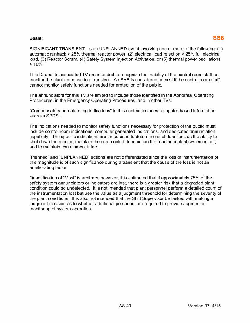
A8-49 Version 37 4/15
Basis: SSSS66 SIGNIFICANT TRANSIENT: is an UNPLANNED event involving one or more of the following: (1) automatic runback > 25% thermal reactor power, (2) electrical load rejection > 25% full electrical load, (3) Reactor Scram, (4) Safety System Injection Activation, or (5) thermal power oscillations > 10%. This IC and its associated TV are intended to recognize the inability of the control room staff to monitor the plant response to a transient. An SAE is considered to exist if the control room staff cannot monitor safety functions needed for protection of the public. The annunciators for this TV are limited to include those identified in the Abnormal Operating Procedures, in the Emergency Operating Procedures, and in other TVs. “Compensatory non-alarming indications” in this context includes computer-based information such as SPDS. The indications needed to monitor safety functions necessary for protection of the public must include control room indications, computer generated indications, and dedicated annunciation capability. The specific indications are those used to determine such functions as the ability to shut down the reactor, maintain the core cooled, to maintain the reactor coolant system intact, and to maintain containment intact. “Planned” and “UNPLANNED” actions are not differentiated since the loss of instrumentation of this magnitude is of such significance during a transient that the cause of the loss is not an ameliorating factor. Quantification of “Most” is arbitrary, however, it is estimated that if approximately 75% of the safety system annunciators or indicators are lost, there is a greater risk that a degraded plant condition could go undetected. It is not intended that plant personnel perform a detailed count of the instrumentation lost but use the value as a judgment threshold for determining the severity of the plant conditions. It is also not intended that the Shift Supervisor be tasked with making a judgment decision as to whether additional personnel are required to provide augmented monitoring of system operation.

A8-50 Version 37 4/15
Initiating Condition: SSAA22 Failure of Reactor Protection System Instrumentation to Complete or Initiate an Automatic Reactor Scram Once a Reactor Protection System Setpoint Has Been Exceeded AND Manual Scram Was Successful.
Operating Mode Applicability: Power Operation (Mode 1) Startup (Mode 2) Threshold Value:
1. Indication(s) exist that a reactor protection setpoint was exceeded
AND
An automatic scram did NOT occur,
AND
A manual scram resulted in the reactor being SUBCRITICAL (IRMs below Range 6 and Period is negative).
Basis: SUBCRITICAL: IRMs below Range 6 and Period is negative This condition indicates failure of the automatic protection system to SCRAM the reactor. This condition is more than a potential degradation of a safety system in that a front line automatic protection system did not function in response to a plant transient and thus the plant safety has been compromised, and design limits of the fuel may have been exceeded. An Alert is indicated because conditions exist that lead to potential loss of fuel clad or RCS. Reactor protection system setpoint being exceeded, rather than limiting safety system setpoint being exceeded, is specified here because failure of the automatic protection system is the issue. A manual scram is any set of actions by the reactor operator(s) at the reactor control console (1/2H11-P603 Panel) which causes control rods to be rapidly inserted into the core and brings the reactor SUBCRITICAL (e.g., reactor trip button, Alternate Rod Insertion). Failure of manual scram would escalate the event to an SAE. The Reactor should be considered SUBCRITICAL when IRMs below Range 6 and Period is negative. A failure of the RPS to shut down the reactor (as indicated by reactor NOT being SUBCRITICAL) is a degraded plant condition that may require the injection of boron to shut down the reactor per EOP guidance. The definition of SUBCRITICAL (IRMs below Range 6 and Period is negative) is the point at which the EOP guidance directs the operators to exit the EOPs and continue shutdown activities with normal plant procedures.

A8-51 Version 37 4/15
Initiating Condition SSAA44
UNPLANNED Loss of Most or All Safety System Annunciation or Indication in Control Room With EITHER (1) a SIGNIFICANT TRANSIENT in Progress, OR (2) Compensatory Non-Alarming Indicators are Unavailable.
Operating Mode Applicability: Power Operation (Mode 1) Startup (Mode 2) Hot Shutdown (Mode 3) Threshold Value: [1 AND (a. OR b.)] 1. UNPLANNED loss of most or all (approximately 75% of annunciators on panels 601, 602, &
603) MCR annunciators or indicators associated with safety systems for > 15 minutes
AND EITHER
a. A SIGNIFICANT TRANSIENT is in progress
OR
b. Compensatory non-alarming indications are NOT available
Basis: UNPLANNED: a parameter change or an event that is not the result of an intended evolution and requires corrective or mitigative actions. SIGNIFICANT TRANSIENT: is an UNPLANNED event involving one or more of the following: (1) automatic runback > 25% thermal reactor power, (2) electrical load rejection > 25% full electrical load, (3) Reactor Scram, (4) Safety System Injection Activation, or (5) thermal power oscillations > 10%. This IC and its associated TVs are intended to recognize the difficulty associated with monitoring changing plant conditions without the use of a major portion of the annunciation or indication equipment during a transient. Recognition of the availability of computer-based indication equipment is considered. “Planned” loss of annunciators or indicators includes scheduled maintenance and testing activities. Quantification of “Most” is arbitrary, however, it is estimated that if approximately 75% of the safety system annunciators or indicators are lost, there is a greater risk that a degraded plant condition could go undetected. It is not intended that plant personnel perform a detailed count of the instrumentation lost but use the value as a judgment threshold for determining the severity of the plant conditions. The concern in this TV is the difficulty associated with assessment of plant conditions. The annunciators or indicators for this TV include those identified in the Abnormal Operating Procedures, in the Emergency Operating Procedures, and in other TVs. “Compensatory non-alarming indications” in this context includes computer based information such as SPDS. If both a major portion of the annunciation system and all computer monitoring are unavailable, the Alert is required.

A8-52 Version 37 4/15
Initiating Condition SSAA55 AC power capability to essential busses reduced to a single power source for greater than 15 minutes such that any additional single failure would result in STATION BLACKOUT.
Operating Mode Applicability: Power Operation (Mode 1) Startup (Mode 2) Hot Shutdown (Mode 3) Threshold Value: (1.a AND 1.b) 1. a. AC power capability to 4160-VAC Emergency Busses 1/2E, 1/2F, and 1/2G reduced to a
single power source for > 15 minutes
AND
b. ANY additional single failure will result in STATION BLACKOUT. Basis: STATION BLACKOUT: is a complete loss of offsite and onsite emergency AC power, as indicated by failure to energize any 4160-VAC Emergency bus. This IC and the associated TVs are intended to provide an escalation from IC SU1, “Loss of All Offsite Power To Essential Busses for Greater Than 15 Minutes.” The condition indicated by this IC is the degradation of the offsite and onsite power systems such that any additional single failure would result in a STATION BLACKOUT. This condition could occur due to a loss of offsite power with a concurrent failure of one emergency generator to supply power to its emergency busses on the Unit NOT being supplied power by the “Swing” diesel generator or two DGs on the other unit.
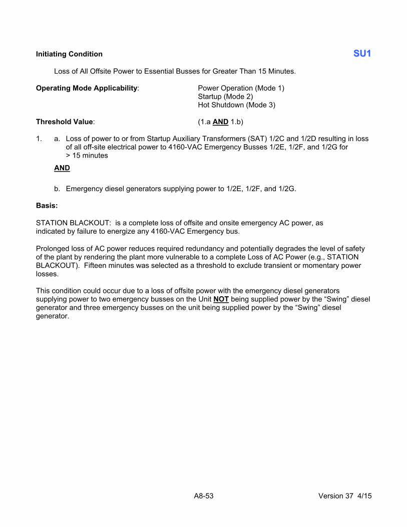
A8-53 Version 37 4/15
Initiating Condition SSUU11 Loss of All Offsite Power to Essential Busses for Greater Than 15 Minutes.
Operating Mode Applicability: Power Operation (Mode 1) Startup (Mode 2) Hot Shutdown (Mode 3) Threshold Value: (1.a AND 1.b) 1. a. Loss of power to or from Startup Auxiliary Transformers (SAT) 1/2C and 1/2D resulting in loss
of all off-site electrical power to 4160-VAC Emergency Busses 1/2E, 1/2F, and 1/2G for > 15 minutes
AND
b. Emergency diesel generators supplying power to 1/2E, 1/2F, and 1/2G. Basis: STATION BLACKOUT: is a complete loss of offsite and onsite emergency AC power, as indicated by failure to energize any 4160-VAC Emergency bus. Prolonged loss of AC power reduces required redundancy and potentially degrades the level of safety of the plant by rendering the plant more vulnerable to a complete Loss of AC Power (e.g., STATION BLACKOUT). Fifteen minutes was selected as a threshold to exclude transient or momentary power losses. This condition could occur due to a loss of offsite power with the emergency diesel generators supplying power to two emergency busses on the Unit NOT being supplied power by the “Swing” diesel generator and three emergency busses on the unit being supplied power by the “Swing” diesel generator.

A8-54 Version 37 4/15
Initiating Condition SSUU22 Inability to Reach Required Shutdown Within Technical Specification Limits.
Operating Mode Applicability: Power Operation (Mode 1) Startup (Mode 2) Hot Shutdown (Mode 3) Threshold Value: 1. Plant is NOT brought to required operating mode within Technical Specifications Limiting
Condition for Operation (LCO) Required Action Statement (RAS) Time limit. Basis: LCOs require the plant to be brought to a designed shutdown mode when the Technical Specification required configuration cannot be restored. Depending on the circumstances, this may or may not be an emergency or precursor to a more severe condition. In any case, the initiation of plant shutdown required by the Technical Specifications requires a 4-hour report under 10 CFR 50.72 (b)(2) Non-emergency events. The plant is within its safety envelope when being shut down within the allowable action statement time in the Technical Specifications. An NUE is required when the plant is not brought to the required operating mode within the allowable action statement time in the Technical Specifications. Declaration of a NUE is based on the time at which the LCO-specified action statement time period elapses under the site Technical Specifications and is not related to how long a condition may have existed. Other required Technical Specification shutdowns that involve precursors to more serious events are addressed by other System Malfunction, Hazards, or Fission Product Barrier Degradation ICs.

A8-55 Version 37 4/15
Initiating Condition SSUU33 UNPLANNED Loss of Most or All Safety System Annunciation or Indication in the Control Room for Greater Than 15 Minutes
Operating Mode Applicability: Power Operation (Mode 1) Startup (Mode 2) Hot Shutdown (Mode 3) Threshold Value: 1. UNPLANNED loss of most or all (approximately 75% of annunciators on panels 601, 602, & 603)
MCR annunciators or indicators associated with safety systems for > 15 minutes. Basis: UNPLANNED: a parameter change or an event that is not the result of an intended evolution and requires corrective or mitigative actions. This IC and its associated TV are intended to recognize the difficulty associated with monitoring changing plant conditions without the use of a major portion of the annunciation or indication equipment. Recognition of the availability of computer-based indication equipment is considered. Quantification of “Most” is arbitrary, however, it is estimated that if approximately 75% of the safety system annunciators or indicators are lost, there is a greater risk that a degraded plant condition could go undetected. It is not intended that plant personnel perform a detailed count of the instrumentation lost, but use the value as a judgment threshold for determining the severity of the plant conditions. The concern in this TV is the difficulty associated with assessment of plant conditions. The annunciators or indicators for this TV include those identified in the Abnormal Operating Procedures, in the Emergency Operating Procedures, and in other TVs. Fifteen minutes was selected as a threshold to exclude transient or momentary power losses. Due to the limited number of safety systems in operation during cold shutdown, refueling, and defueled modes, no IC is indicated during these modes of operation.

A8-56 Version 37 4/15
Initiating Condition SSUU44 Fuel Clad Degradation.
Operating Mode Applicability: Power Operation (Mode 1) Startup (Mode 2) Hot Shutdown (Mode 3) Threshold Values: (1 OR 2)
NOTE: Use the Unit 1 or Unit 2 Pretreatment (Flow vs. mR/hr) Graphs in the Curve Book in the Control Room to determine if the Pretreatment Radiation Monitor exceeds the TV of 240,000 µCi/sec.
1. Valid reading on Pretreatment Radiation Monitor greater than 240,000 µCi/sec for greater than
60 minutes.
OR
2. Reactor coolant specific activity > 0.2 µCi/gm and ≤ 2.0 µCi/gm dose equivalent I-131 for > 48 hours.
OR Reactor coolant specific activity > 2.0 µCi/gm dose equivalent I-131. Basis: VALID: an indication, report, or condition, is considered to be VALID when it is verified by (1) an instrument channel check, or (2) indications on related or redundant indicators, or (3) by direct observation by plant personnel, such that doubt related to the indicator’s operability, the condition’s existence, or the report’s accuracy is removed. Implicit in this definition is the need for timely assessment. This IC is included as a NUE because it is considered to be a potential degradation in the level of safety of the plant and a potential precursor of more serious problems. TV #1 addresses the specific failed fuel monitor that provides indication of fuel clad integrity. TV #2 addresses coolant samples exceeding coolant technical specifications for iodine spike.

A8-57 Version 37 4/15
Initiating Condition SSUU55 RCS Leakage.
Operating Mode Applicability: Power Operation (Mode 1) Startup (Mode 2) Hot Shutdown (Mode 3) Threshold Values: (1 OR 2) 1. UNIDENTIFIED OR pressure boundary leakage > 10 gpm.
OR
2. IDENTIFIED leakage > 25 gpm. Basis: IDENTIFIED leakage: Is defined as the rate of leakage into the Drywell equipment drain system. UNIDENTIFIED leakage: Is defined as the rate of leakage into the Drywell floor drain system. This IC is included as a NUE because it may be a precursor of more serious conditions and, as a result, is considered to be a potential degradation of the level of safety of the plant. The 10-gpm value for the UNIDENTIFIED and pressure boundary leakage was selected as it is observable with normal control room indications. Lesser values must generally be determined through time-consuming surveillance tests. The TV for identified leakage is set at a higher value due to the lesser significance of IDENTIFIED leakage in comparison to UNIDENTIFIED or pressure boundary leakage.

A8-58 Version 37 4/15
Initiating Condition SSUU66 UNPLANNED Loss of All Onsite OR Offsite Communications Capabilities.
Operating Mode Applicability: Power Operation (Mode 1) Startup (Mode 2) Hot Shutdown (Mode 3) Threshold Values: (1 OR 2) 1. UNPLANNED loss of ALL of the following onsite communications capability affecting the ability to
perform routine operations:
In-plant telephones (includes hardwired and wireless)
Plant page
Plant radio systems
OR
2. UNPLANNED loss of ALL of the following offsite communications capability:
ENN (Emergency Notification Network)
ENS (Emergency Notification System)
Commercial phones (Radio, PBX, Satellite, Wireless)
VOIP (Voice Over Internet Protocol)
OPX (Off Premise Extension)
Basis: UNPLANNED: a parameter change or an event that is not the result of an intended evolution and requires corrective or mitigative actions. The purpose of this IC and its associated TVs is to recognize a loss of communications capability that either defeats the plant operations staff ability to perform routine tasks necessary for plant operations or the ability to communicate problems with offsite authorities. The availability of one method of ordinary offsite communications is sufficient to inform State and local authorities of plant conditions. This TV is intended to be used only when extraordinary means are being used to make communications possible. The list for onsite communications loss encompasses the loss of all means of routine communications. The list for offsite communications loss encompasses the loss of all means of communications with offsite authorities.

A8-59 Version 37 4/15
Initiating Condition SSUU88 Inadvertent Criticality.
Operating Mode Applicability: Hot Shutdown (Mode 3) Threshold Value: 1. An UNPLANNED extended positive period observed on nuclear instrumentation. Basis: UNPLANNED: a parameter change or an event that is not the result of an intended evolution and requires corrective or mitigative actions. This IC addresses inadvertent criticality events. While the primary concern of this IC is criticality events that occur in Cold Shutdown or Refueling modes, the IC is applicable in other modes in which inadvertent criticalities are possible. This IC indicates a potential degradation of the level of safety of the plant, warranting a NUE classification. This condition is identified using the period monitors. The term “extended” is used in order to allow exclusion of expected short-term positive period from planned control rod movements. These short-term positive periods are the result of the rise in neutron population due to SUBCRITICAL multiplication.

6.4 Category C - Cold Shutdown System Malfunctions

A8-61 Version 37 4/15
Initiating Condition CCGG11 Loss of RPV Inventory Affecting Fuel Clad Integrity with Containment Challenged with Irradiated Fuel in the RPV.
Operating Mode Applicability: Cold Shutdown (Mode 4) Refueling (Mode 5) Threshold Values: [1 AND (2.a. OR 2.b.) AND 3] 1. Loss of RPV inventory as indicated by unexplained level rise in any of the following:
Drywell Floor Drain Sumps
Drywell Equipment Drain Sumps
Torus
Torus Room Sumps
Reactor Building Floor Drain Sumps
Turbine Building Floor Drain Sumps
Rad Waste Tanks
AND
2. RPV Level:
a. Less than -155” (TAF) for > 30 minutes
OR
b. RPV level CANNOT be monitored WITH indication of core uncovery for > 30 minutes as evidenced by EITHER of the following:
DWRRM 1/2D11-K621A(B): > 9.5 R/hr
Erratic Source Range Monitor Indication
AND
3. Primary Containment challenged as indicated by any of the following:
Explosive mixture inside Primary Containment: H2 ≥ 6%
AND
O2 ≥ 5%
Primary Containment Pressure: ≥ 56 psig
Secondary CONTAINMENT INTEGRITY NOT established
Secondary Containment radiation monitors: Greater than Max Safe values (SC EOP - Table 6)

A8-62 Version 37 4/15
Basis: CCGG11 CONTAINMENT INTEGRITY: Primary Containment OPERABLE per Technical Specification 3.6.1.1. Secondary Containment OPERABLE per Technical Specification 3.6.4.1. For TV 1 in the cold shutdown mode, normal RCS level and RPV level instrumentation systems will normally be available. In the refueling mode, normal means of RPV level indication may not be available. Redundant means of RPV level indication will be normally installed to assure that the ability to monitor level will not be interrupted. For both cold shutdown and refueling modes sump and tank level rises must be evaluated against other potential sources of leakage such as cooling water sources inside the containment to ensure they are indicative of RCS leakage. TV 2 represents the inability to restore and maintain RPV level to above the top of active fuel. Fuel damage is probable if RPV level cannot be restored, as available decay heat will cause boiling, further reducing the RPV level. (Water level calculated for top of active fuel in calculation SMNH-05-009 Version 2 was -158.44”. Although slightly more conservative, the -155” EOP value for top of active fuel is provided for this EAL to aid in operator recognition of this event.) NRC analysis indicates that core damage may occur within an hour following continued core uncovery therefore, conservatively, 30 minutes was chosen. As water level in the RPV lowers, the dose rate above the core will rise. The dose rate due to this core shine should result in elevated DWRRM indication and possible alarm. Post-TMI studies indicated that the installed nuclear instrumentation will operate erratically when the core is uncovered and that this should be used as a tool for making such determinations. The GE is declared on the occurrence of the loss or imminent loss of function of all three barriers. Based on the above discussion, RCS barrier failure resulting in core uncovery for 30 minutes or more may cause fuel clad failure. With the primary containment breached or challenged then the potential for unmonitored fission product release to the environment is high. This represents a direct path for radioactive inventory to be released to the environment. This is consistent with the definition of a GE. In the early stages of a core uncovery event, it is unlikely that hydrogen buildup due to a core uncovery could result in an explosive mixture of dissolved gasses in CONTAINMENT. However, CONTAINMENT monitoring and/or sampling should be performed to verify this assumption and a GE declared if it is determined that an explosive mixture exists.

A8-63 Version 37 4/15
Initiating Condition CCSS11 Loss of RPV Inventory Affecting Core Decay Heat Removal Capability.
Operating Mode Applicability: Cold Shutdown (Mode 4) Threshold Values: [(1.a. OR 1.b.) OR (2.a. OR 2.b.)] 1. Loss of RPV inventory affecting core decay heat removal capability with Secondary
CONTAINMENT INTEGRITY NOT established as indicated by:
a. RPV level < - 41” (6” below the Level 2 actuation setpoint)
OR
b. RPV level CANNOT be monitored for > 30 minutes with a possible loss of RPV inventory as indicated by unexplained level rise in any of the following:
Drywell Floor Drain Sumps
Drywell Equipment Drain Sumps
Torus
Torus Room Sumps
Reactor Building Floor Drain Sumps
Turbine Building Floor Drain Sumps
Rad Waste Tanks
OR
2. Loss of RPV inventory affecting core decay heat removal capability with Secondary CONTAINMENT INTEGRITY established as indicated by:
a. RPV level < -155” (TAF)
OR
b. RPV level CANNOT be monitored for > 30 minutes with a possible loss of RPV inventory as indicated by EITHER:
Unexplained level rise in any of the following:
Drywell Floor Drain Sumps
Drywell Equipment Drain Sumps
Torus
Torus Room Sumps
Reactor Building Floor Drain Sumps
Turbine Building Floor Drain Sumps
Rad Waste Tanks
OR
Erratic Source Range Monitor Indication

A8-64 Version 37 4/15
Basis: CCSS11 CONTAINMENT INTEGRITY: Primary Containment OPERABLE per Technical Specification 3.6.1.1. Secondary Containment OPERABLE per Technical Specification 3.6.4.1. Under the conditions specified by this IC, continued lowering in RPV level is indicative of a loss of inventory control. Inventory loss may be due to an RPV breach, pressure boundary leakage, or continued boiling in the RPV. In cold shutdown the decay heat available to raise RCS temperature during a loss of inventory or heat removal event may be significantly greater than in the refueling mode. Sump and tank level rises must be evaluated against other potential sources of leakage such as cooling water sources inside the containment to ensure they are indicative of RCS leakage. The 30-minute duration allows sufficient time for actions to be performed to recover needed cooling equipment. (Water level calculated for top of active fuel in calculation SMNH-05-009 Version 2 was -158.44”. Although slightly more conservative, the -155” EOP value for top of active fuel is provided for this EAL to aid in operator recognition of this event.) Post-TMI studies indicated that the installed nuclear instrumentation will operate erratically when the core is uncovered and that this should be used as a tool for making such determinations.

A8-65 Version 37 4/15
Initiating Condition CCSS22 Loss of RPV Inventory Affecting Core Decay Heat Removal Capability with Irradiated Fuel in the RPV.
Operating Mode Applicability: Refueling (Mode 5) Threshold Values: [(1.a. OR 1.b.) OR (2.a. OR 2.b.)] 1. WITH Secondary CONTAINMENT INTEGRITY NOT established:
a. RPV level < - 41” (6” below the Level 2 actuation setpoint)
OR
b. RPV level CANNOT be monitored WITH indication of core uncovery as evidenced by EITHER of the following:
Drywell Wide Range Radiation Monitor (DWRRM) 1/2D11-K621A(B) > 9.5 R/hr.
Erratic Source Range Monitor Indication
OR
2. WITH Secondary CONTAINMENT INTEGRITY established
a. RPV level < -155” (TAF)
OR
b. RPV level CANNOT be monitored WITH Indication of core uncovery as evidenced by EITHER of the following:
DWRRM 1/2D11-K621A(B) > 9.5 R/hr
Erratic Source Range Monitor Indication

A8-66 Version 37 4/15
Basis: CCSS22 CONTAINMENT INTEGRITY: Primary Containment OPERABLE per Technical Specification 3.6.1.1. Secondary Containment OPERABLE per Technical Specification 3.6.4.1. Under the conditions specified by this IC, continued lowering in RPV level is indicative of a loss of inventory control. Inventory loss may be due to an RPV breach or continued boiling in the RPV. In cold shutdown the decay heat available to raise RCS temperature during a loss of inventory or heat removal event may be significantly greater than in the refueling mode. As water level in the RPV lowers, the dose rate above the core will rise. The dose rate due to this core shine should result in elevated DWRRM indication and possible alarm. For TV 1.b and TV 2.b, calculations were performed to conservatively estimate a site-specific dose rate setpoint indicative of core uncovery. Additionally, post-TMI studies indicated that the installed nuclear instrumentation will operate erratically when the core is uncovered and that this should be used as a tool for making such determinations. For TV 2 in the refueling mode, normal means of RPV level indication may not be available. Redundant means of RPV level indication will be normally installed to assure that the ability to monitor level will not be interrupted. (Water level calculated for top of active fuel in calculation SMNH-05-009 Version 2 was -158.44”. Although slightly more conservative, the -155” EOP value for top of active fuel is provided for this EAL to aid in operator recognition of this event.) This effluent release is not expected with Secondary CONTAINMENT INTEGRITY established.

A8-67 Version 37 4/15
Initiating Condition CCAA11 Loss of RCS Inventory.
Operating Mode Applicability: Cold Shutdown (Mode 4) Threshold Values: [1 OR (2.a. AND 2.b.)] 1. Loss of RCS inventory as indicated by RPV level < -35” (Level 2 actuation setpoint)
OR
2. a. RPV level CANNOT be monitored for > 15 minutes
AND
b. A loss of RCS inventory may be occurring as indicated by unexplained level rise in any of the following:
Drywell Floor Drain Sumps
Drywell Equipment Drain Sumps
Torus
Torus Room Sumps
Reactor Building Floor Drain Sumps
Turbine Building Floor Drain Sumps
Rad Waste Tanks
Basis: These TVs serve as precursors to a loss of ability to adequately cool the fuel. The magnitude of this loss of water indicates that makeup systems have not been effective and may not be capable of preventing further RPV level lowering and potential core uncovery. The Level 2 Actuation Setpoint was chosen because it is a standard setpoint at which High Pressure injection systems automatically start during normal operations (Modes 1-3). The inability to restore and maintain level after reaching this setpoint would therefore be indicative of a failure of the RCS barrier. In the cold shutdown mode, normal RCS level and RPV level instrumentation systems will normally be available. However, if all level indication were to be lost during a loss of RCS inventory event, the operators would need to determine that RPV inventory loss was occurring by observing sump and tank level changes. Sump and tank level rises must be evaluated against other potential sources of leakage such as cooling water sources inside the containment to ensure they are indicative of RCS leakage.

A8-68 Version 37 4/15
Initiating Condition CCAA22 Loss of RPV Inventory with Irradiated Fuel in the RPV.
Operating Mode Applicability: Refueling (Mode 5) Threshold Values: [1 OR (2.a. AND 2.b.)] 1. Loss of RCS inventory as indicated by RPV level < -35” (Level 2 actuation setpoint)
OR
2. a. RPV level CANNOT be monitored for > 15 minutes
AND
b. A loss of RCS inventory may be occurring as indicated by unexplained level rise in any of the following:
Drywell Floor Drain Sumps
Drywell Equipment Drain Sumps
Torus
Torus Room Sumps
Reactor Building Floor Drain Sumps
Turbine Building Floor Drain Sumps
Rad Waste Tanks
Basis: These TVs serve as precursors to a loss of heat removal. The magnitude of this loss of water indicates that makeup systems have not been effective and may not be capable of preventing further RPV level lowering and potential core uncovery. The Level 2 Actuation Setpoint was chosen because it is a standard setpoint at which High Pressure injection systems automatically start during normal operations (Modes 1-3). The inability to restore and maintain level after reaching this setpoint would therefore be indicative of a failure of the RCS barrier. In the refueling mode, normal means of RPV level indication may not be available. Redundant means of RPV level indication will be normally installed to assure that the ability to monitor level will not be interrupted. Sump and tank level rises must be evaluated against other potential sources of leakage such as cooling water sources inside the containment to ensure they are indicative of RCS leakage.

A8-69 Version 37 4/15
Initiating Condition CCAA33 Loss of All Offsite Power AND Loss of All Onsite AC Power to Essential Busses.
Operating Mode Applicability: Cold Shutdown (Mode 4) Refueling (Mode 5) Defueled Threshold Value: (1.a AND 1.b AND 1.c) 1. a. Loss of power to or from Startup Auxiliary Transformers (SAT) 1/2C and 1/2D resulting in loss
of all offsite electrical power to 4160-VAC Emergency Busses 1/2E, 1/2F, and 1/2G.
AND
b. Failure of emergency diesel generators to supply power to emergency busses.
AND
c. Failure to restore power to at least one emergency bus within 15 minutes from the time of loss of both offsite and onsite AC power.
Basis: Loss of all AC power compromises all plant safety systems requiring electric power including RHR, ECCS, Containment Heat Removal, Spent Fuel Heat Removal, and the Ultimate Heat Sink. When in cold shutdown, refueling, or defueled mode the event can be classified as an Alert, because of the significantly reduced decay heat, lower temperature, and pressure, increasing the time available to restore one of the emergency busses relative to that specified for the SAE TV. Fifteen minutes was selected as a threshold to exclude transient or momentary power losses. Consideration should be given to operable loads necessary to remove decay heat or provide Reactor Vessel makeup capability when evaluating loss of AC power to emergency busses. Even though an emergency bus may be energized, if necessary loads are not operable on the energized bus then the bus should not be considered operable.

A8-70 Version 37 4/15
Initiating Condition CCAA44 Inability to Maintain Plant in Cold Shutdown with Irradiated Fuel in the RPV.
Operating Mode Applicability: Cold Shutdown (Mode 4) Refueling (Mode 5)
Threshold Values: [1.a. AND 1.b.] OR [2.a. AND (2.b. OR 2.c.)] OR [3.a. OR 3.b.] 1. An UNPLANNED event results in RCS temperature exceeding 212oF with:
a. Secondary CONTAINMENT INTEGRITY NOT established
AND
b. RCS integrity NOT established
NOTES: • The ED should not wait until the indicated time of TVs 2 or 3 have elapsed, but should declare the event as soon as it is determined that the duration that RCS temperature exceeds 212o F has or will likely be exceeded.
• If an RCS heat removal system is in operation within this time frame and RCS temperature is being reduced, then TVs 2 and 3 are not applicable.
OR
2. An UNPLANNED event results in RCS temperature exceeding 212oF for > 20 minutes with:
a. Secondary CONTAINMENT INTEGRITY established
AND
b. RCS integrity NOT established
OR
c. RCS inventory reduced.
OR
3. An UNPLANNED event results in:
a. RCS temperature exceeding 212oF for > 60 minutes
OR
b. RPV pressure increasing > 10 psig

A8-71 Version 37 4/15
Basis: CCAA44 UNPLANNED: a parameter change or an event that is not the result of an intended evolution and requires corrective or mitigative actions. CONTAINMENT INTEGRITY: Primary Containment OPERABLE per Technical Specification 3.6.1.1. Secondary Containment OPERABLE per Technical Specification 3.6.4.1. TV 1 addresses complete loss of functions required for core cooling during refueling and cold shutdown modes when neither Secondary CONTAINMENT INTEGRITY nor RCS integrity are established. No delay time is allowed for TV 1 because the evaporated reactor coolant that may be released into the Containment during this heatup condition could also be directly released to the environment. RCS integrity is in place when the RCS pressure boundary is in its normal condition for the cold shutdown mode of operation (e.g., no freeze seals or nozzle dams). TV 2 addresses the complete loss of functions required for core cooling for GREATER THAN 20 minutes during refueling and cold shutdown modes when Secondary CONTAINMENT INTEGRITY is established but RCS integrity is not established or RCS inventory is reduced. The allowed 20 minute time frame was included to allow operator action to restore the heat removal function, if possible. TV 3 addresses complete loss of functions required for core cooling for > 60 minutes during refueling and cold shutdown modes when RCS integrity is established. As in TV 1 and 2, RCS integrity should be considered to be in place when the RCS pressure boundary is in its normal condition for the cold shutdown mode of operation. The status of Secondary CONTAINMENT INTEGRITY in this TV is immaterial given that the RCS is providing a high pressure barrier to fission product release to the environment. The 60-minute time frame should allow sufficient time to restore cooling without there being a substantial degradation in plant safety. The 10-psig pressure rise covers situations where, due to high decay heat loads, the time provided to restore temperature control should be less than 60 minutes. The RCS pressure setpoint chosen is 10 psig and can be read on Control Board instrumentation. The Note indicates that TV 3 is not applicable if actions are successful in restoring an RCS heat removal system to operation and RCS temperature is being reduced within the 60-minute time frame, assuming that the RCS pressure rise has remained < 10 psig. NRC analyses show that sequences can cause core uncovery in 15 to 20 minutes and severe core damage within an hour after decay heat removal is lost. The ED must remain alert to events or conditions that lead to the conclusion that exceeding the TV is imminent. If, in the judgment of the ED, an imminent situation is at hand, the classification should be made as if the threshold has been exceeded.

A8-72 Version 37 4/15
Initiating Condition CCUU11 RCS Leakage.
Operating Mode Applicability: Cold Shutdown (Mode 4) Threshold Values: 1. Unable to establish or maintain RPV level > +3”. Basis: This IC is included as a NUE because it is considered to be a potential degradation of the level of safety of the plant. Prolonged loss of RCS Inventory may result in escalation to the Alert level via either IC CA1 (Loss of RCS Inventory) or CA4 (Inability to Maintain Plant in Cold Shutdown with Irradiated Fuel in the RPV). The difference between CU1 and CU2 deals with the RCS conditions that exist between cold shutdown and refueling mode applicability. In cold shutdown the RCS will normally be intact and RCS inventory and level monitoring means are normally available. In the refueling mode the RCS is not intact and RPV level and inventory are monitored by different means. Expanded basis for these assumptions is provided NEI 99-01, Rev. 4 (NUMARC/NESP-007), ”Methodology for Development of Emergency Action Levels”, January 2003.

A8-73 Version 37 4/15
Initiating Condition CCUU22 UNPLANNED Loss of RCS Inventory with Irradiated Fuel in the RPV.
Operating Mode Applicability: Refueling (Mode 5) Threshold Values: [1 OR (2.a. AND 2.b.)] 1. UNPLANNED RWL lowering below the RPV flange for ≥ 15 minutes
OR
2. a. RPV level CANNOT be monitored
AND
b. A loss of RPV inventory may be occurring as indicated by unexplained level rise in any of the following:
Drywell Floor Drain Sumps
Drywell Equipment Drain Sumps
Torus
Torus Room Sumps
Reactor Building Floor Drain Sumps
Turbine Building Floor Drain Sumps
Rad Waste Tanks Basis: UNPLANNED: a parameter change or an event that is not the result of an intended evolution and requires corrective or mitigative actions. This IC is included as a NUE because it may be a precursor of more serious conditions and, as a result, is considered to be a potential degradation of the level of safety of the plant. Refueling evolutions that lower RWL below the RPV flange are carefully planned and procedurally controlled. An UNPLANNED event that results in water level decreasing below the RPV flange warrants declaration of a NUE due to the reduced RCS inventory that is available to keep the core covered. TV 1 involves a lowering in RWL below the top of the RPV flange that continues for 15 minutes due to an UNPLANNED event. The allowance of 15 minutes was chosen because it is reasonable to assume that level can be restored within this time frame using any of the redundant means of refill that should be available. In the refueling mode, normal means of core temperature indication and RWL indication may not be available. Redundant means of RPV level indication will normally be installed (including the ability to monitor level visually) to assure that the ability to monitor level will not be interrupted. However, if all level indication were to be lost during a loss of RCS inventory event, the operators would need to determine that RPV inventory loss was occurring by observing sump and tank level changes. Sump and tank level rises must be evaluated against other potential sources of leakage such as cooling water sources inside the containment to ensure they are indicative of RCS leakage.

A8-74 Version 37 4/15
Initiating Condition CCUU33 Loss of All Offsite Power to Essential Busses for Greater Than 15 Minutes.
Operating Mode Applicability: Cold Shutdown (Mode 4) Refueling (Mode 5) Threshold Value: (1.a. AND 1.b.) 1. a. Loss of power to or from Startup Auxiliary Transformers (SAT) 1/2C and 1/2D resulting in loss of
all offsite electrical power to 4160-VAC Emergency Busses 1/2E, 1/2F, and 1/2G for > 15 minutes
AND
b. One emergency diesel generator supplying power to 1/2E, 1/2F, or 1/2G. Basis: Prolonged loss of AC power reduces required redundancy and potentially degrades the level of safety of the plant by rendering the plant more vulnerable to a complete Loss of AC Power. Fifteen minutes was selected as a threshold to exclude transient or momentary power losses.

A8-75 Version 37 4/15
Initiating Condition CCUU44 UNPLANNED Loss of Decay Heat Removal Capability with Irradiated Fuel in the RPV.
Operating Mode Applicability: Cold Shutdown (Mode 4) Refueling (Mode 5) Threshold Values: (1 OR 2)
NOTE: The ED should not wait until 15 minutes have elapsed, but should declare the event as soon as it is determined that the duration of the loss of RCS temperature AND RPV level indication has or will likely exceed 15 minutes.
1. An UNPLANNED event results in RCS temperature exceeding 212°F.
OR
2. Loss of all RCS temperature AND RPV level indication for > 15 minutes. Basis: UNPLANNED: a parameter change or an event that is not the result of an intended evolution and requires corrective or mitigative actions. This IC is included as a NUE because it may be a precursor of more serious conditions and, as a result, is considered to be a potential degradation of the level of safety of the plant. During refueling the level in the RPV will normally be maintained above the RPV flange. Refueling evolutions that lower water level below the RPV flange are carefully planned and procedurally controlled. Loss of forced decay heat removal at reduced inventory may result in more rapid rises in RCS/RPV temperatures depending on the time since shutdown. The ED must remain attentive to events or conditions that lead to the conclusion that exceeding the TV is imminent. If, in the judgment of the ED, an imminent situation is at hand, the classification should be made as if the threshold has been exceeded.

A8-76 Version 37 4/15
Initiating Condition CCUU66 UNPLANNED Loss of All Onsite OR Offsite Communications Capabilities.
Operating Mode Applicability: Cold Shutdown (Mode 4) Refueling (Mode 5) Threshold Values: (1 OR 2) 1. UNPLANNED loss of ALL of the following onsite communications capability affecting the ability
to perform routine operations:
Plant telephones (Includes hardwired and wireless)
Plant page
Plant radio systems
OR
2. UNPLANNED loss of ALL of the following offsite communications capability:
ENN (Emergency Notification Network)
ENS (Emergency Notification System)
Commercial phones (Radio, PBX, Satellite, Wireless)
VOIP (Voice Over Internet Protocol)
OPX (Off Premise Extension)
Basis: UNPLANNED: a parameter change or an event that is not the result of an intended evolution and requires corrective or mitigative actions. The purpose of this IC and its associated TVs is to recognize a loss of communications capability that either defeats the plant operations staff ability to perform routine tasks necessary for plant operations or the ability to communicate problems with offsite authorities. The availability of one method of ordinary offsite communications is sufficient to inform State and local authorities of plant problems. This TV is intended to be used only when extraordinary means are being utilized to make communications possible.

A8-77 Version 37 4/15
Initiating Condition CCUU77 UNPLANNED Loss of Required DC Power for Greater than 15 Minutes.
Operating Mode Applicability: Cold Shutdown (Mode 4) Refueling (Mode 5)
Threshold Value: (1.a. AND 1.b.) 1. a. UNPLANNED loss of DC power to 125/250 VDC Bus 1/2R22-S016 & 1/2R22-S017
indicated by bus voltage indications < 105/210 VDC
AND
b. Failure to restore power to at least one DC bus within 15 minutes from the time of loss. Basis: UNPLANNED: a parameter change or an event that is not the result of an intended evolution and requires corrective or mitigative actions. The purpose of this IC and its associated TVs is to recognize a loss of DC power compromising the ability to monitor and control the removal of decay heat during Cold Shutdown or Refueling operations. This TV is intended to be anticipatory in as much as the operating crew may not have necessary indication and control of equipment needed to respond to the loss. UNPLANNED is included to preclude the declaration of an emergency as a result of planned maintenance activities. 105/210-VDC bus voltage is based on the minimum bus voltage necessary for the operation of safety-related equipment. This voltage value incorporates a margin of at least 15 minutes of operation before the onset of inability to operate those loads.

A8-78 Version 37 4/15
Initiating Condition CCUU88 Inadvertent Criticality.
Operating Mode Applicability: Cold Shutdown (Mode 4) Refueling (Mode 5) Threshold Values: 1. An UNPLANNED extended positive period observed on nuclear instrumentation. Basis: UNPLANNED: a parameter change or an event that is not the result of an intended evolution and requires corrective or mitigative actions. This IC indicates a potential degradation of the level of safety of the plant, warranting a NUE classification. The term “extended” is used in order to allow exclusion of expected short-term positive periods from planned fuel bundle or control rod movements during core alterations. These short term positive periods are the result of the rise in neutron population due to SUBCRITICAL multiplication.

6.5 Category E - ISFSI Events

A8-80 Version 37 4/15
Initiating Condition EE--HHUU11 Damage to a loaded cask CONFINEMENT BOUNDARY.
Operating Mode Applicability: ALL Threshold Value: 1. Damage to a loaded dry fuel storage cask CONFINEMENT BOUNDARY due to natural
phenomena events, accident conditions, or any condition in the opinion of the ED that affects or causes a loss of loaded dry fuel storage cask CONFINEMENT BOUNDARY.
Basis: CONFINEMENT BOUNDARY: is the barrier(s) between areas containing radioactive substances and the environment. A NUE in this IC is categorized on the basis of the occurrence of an event of sufficient magnitude that a loaded cask CONFINEMENT BOUNDARY is damaged or violated. This includes classification based on a loaded fuel storage cask CONFINEMENT BOUNDARY loss leading to the degradation of the fuel during storage or posing an operational safety problem with respect to its removal from storage. Any condition not explicitly detailed as a TV, which, in the judgment of the ED, is a potential degradation in the level of safety of the ISFSI. ED judgment is to be based on known conditions and the expected response to mitigating activities within a short time period.

A8-81 Version 37 4/15
6.6 Category H - Hazards and Others

A8-82 Version 37 4/15
Initiating Condition HHGG11 HOSTILE ACTION resulting in loss of physical control of the facility.
Operating Mode Applicability: All Threshold Value: (1 OR 2) 1. A HOSTILE ACTION has occurred such that plant personnel are unable to operate equipment
required to maintain safety functions. OR 2. A HOSTILE ACTION has caused failure of Spent Fuel Cooling Systems and IMMINENT fuel
damage is likely when calculated SFP Time to Boil (Saturation Time) is 2 hours or less as defined in 34AB-G41-001-1/2 or 34AB-E11-001-1/2.
Basis: HOSTILE ACTION: An act toward a NPP or its personnel that includes the use of violent force to destroy equipment, take HOSTAGES, and/or intimidate the licensee to achieve an end. This includes attack by air, land, or water using guns, explosives, PROJECTILEs, vehicles, or other devices used to deliver destructive force. Other acts that satisfy the overall intent may be included. HOSTILE ACTION should not be construed to include acts of civil disobedience or felonious acts that are not part of a concerted attack on the NPP. Non-terrorism based EALs should be used to address such activities (i.e., this may include violent acts between individuals in the owner controlled area).
IMMINENT: Mitigation actions have been ineffective, additional actions are not expected to be successful, and trended information indicates that the event or condition will occur. The first TV encompasses conditions under which a HOSTILE ACTION has resulted in loss of physical control of VITAL AREAs (containing vital equipment or controls of vital equipment) required to maintain safety functions and control of that equipment cannot be transferred to and operated from another location. These safety functions are reactivity control, reactor water level, and decay heat removal. If control of the plant equipment necessary to maintain safety functions can be transferred to another location, then the above initiating condition is not met. Loss of physical control of the control room or remote shutdown capability alone may not prevent the ability to maintain safety functions per se. Design of the remote shutdown capability and the location of the transfer switches should be taken into account. The second TV addresses the loss of physical control of spent fuel pool cooling systems if imminent fuel damage is likely. This EAL addresses failure of spent fuel cooling systems as a result of HOSTILE ACTION if IMMINENT fuel damage is likely, such as when a freshly off-loaded reactor core is in the spent fuel pool or RPV cavity. IMMINENT fuel damage is likely when the calculated SFP Time to Boil (Saturation Time) in 34AB-G41-001-1/2 or 34AB-E11-001-1/2 is 2 hours or less.

A8-83 Version 37 4/15
Initiating Condition HHGG22 Other Conditions Existing Which in the Judgment of the ED Warrant Declaration of General Emergency.
Operating Mode Applicability: All Threshold Value: 1. Other conditions exist which in the judgment of the ED indicate that events are in process or have
occurred which involve actual or imminent substantial core degradation or melting with potential for loss of CONTAINMENT INTEGRITY or HOSTILE ACTION that results in an actual loss of physical control of the facility. Releases can be reasonably expected to exceed EPA PAG exposure levels offsite for more than the immediate site area.
Basis: CONTAINMENT INTEGRITY: Primary Containment OPERABLE per Technical Specification 3.6.1.1. Secondary Containment OPERABLE per Technical Specification 3.6.4.1. HOSTILE ACTION: An act toward an NPP or its personnel that includes the use of violent force to destroy equipment, takes hostages, and /or intimidates the licensee to achieve an end. This includes attack by air, land, or water using guns, explosives, projectiles, vehicles, or other devices used to deliver destructive force. Other acts that satisfy the overall intent may be included. HOSTILE ACTION should not be construed to include acts of civil disobedience or felonious acts that are not part of a concerted attack on the NPP. Non-terrorism-based EALs should be used to address such activities, (e.g., violent acts between individuals in the owner controlled area.) This TV is intended to address unanticipated conditions not addressed explicitly elsewhere but that warrant declaration of an emergency because conditions exist which are believed by the ED to fall under the GE class.

A8-84 Version 37 4/15
Initiating Condition HHSS22 Control Room Evacuation Has Been Initiated AND Plant Control Cannot Be Established.
Operating Mode Applicability: All Threshold Value: (1.a. AND 1.b.) 1. a. Control Room evacuation has been initiated
AND
b. Control of the plant can NOT be established per 31RS-OPS-001-1/2 “Shutdown From Outside The Control Room,” within 15 minutes.
Basis: Expeditious transfer of safety systems has not occurred but fission product barrier damage may not yet be indicated. The intent of this IC is to capture those events where control of the plant cannot be reestablished in a timely manner. The time for transfer is based on analysis or assessments as to how quickly control must be reestablished without core uncovering and/or core damage. The determination of whether or not control is established at the remote shutdown panel is based on ED judgment. The ED is expected to make a reasonable, informed judgment within the time for transfer that the operators have control of the plant. The intent of the TV is to establish control of important plant equipment and knowledge of important plant parameters in a timely manner. Primary emphasis should be placed on those components and instruments that supply protection for and information about safety functions. These safety functions are reactivity control (ability to shutdown the reactor and maintain it shutdown), reactor water level (ability to cool the core), and decay heat removal (ability to maintain a heat sink).

A8-85 Version 37 4/15
Initiating Condition HHSS33 Other Conditions Existing Which in the Judgment of the ED Warrant Declaration of Site Area Emergency.
Operating Mode Applicability: All Threshold Value: 1. Other conditions exist which in the judgment of the ED indicate that Events are in process or have
occurred which involve actual or likely major failures of plant functions needed for protection of the public or HOSTILE ACTION that results in intentional damage or malicious acts (1) toward site personnel or equipment that could lead to the likely failure of, or (2) that prevent effective access to, equipment needed for the protection of the public. Any releases are not expected to result in exposure levels that exceed EPA PAG exposure levels beyond the site boundary.
Basis: HOSTILE ACTION: An act toward an NPP or its personnel that includes the use of violent force to destroy equipment, take hostages, and /or intimidate the licensee to achieve an end. This includes attack by air, land, or water using weapons, explosives, projectiles, vehicles, or other devices used to deliver destructive force. Other acts that satisfy the overall intent may be included. HOSTILE ACTION should not be construed to include acts of civil disobedience or felonious acts that are not part of a concerted attack on the NPP. Non-terrorism-based EALs should be used to address such activities, (e.g., violent acts between individuals in the owner controlled area.) This TV is intended to address unanticipated conditions not addressed explicitly elsewhere but that warrant declaration of an emergency because conditions exist which are believed by the ED to fall under the emergency class description for SAE.

A8-86 Version 37 4/15
Initiating Condition HHSS44
HOSTILE ACTION within the PROTECTED AREA. Operating Mode Applicability: All Threshold Value: 1. A HOSTILE ACTION is occurring or has occurred within the PROTECTED AREA as reported by
the Security Shift Captain or designee.
Basis: HOSTILE ACTION: An act toward a Nuclear Power Plant (NPP) or its personnel that includes the use of violent force to destroy equipment, take hostages, and /or intimidate the licensee to achieve an end. This includes attack by air, land, or water using weapons, explosives, projectiles, vehicles, or other devices used to deliver destructive force. Other acts that satisfy the overall intent may be included. HOSTILE ACTION should not be construed to include acts of civil disobedience or felonious acts that are not part of a concerted attack on the NPP. Non-terrorism-based EALs should be used to address such activities, (e.g., violent acts between individuals in the owner controlled area.) PROTECTED AREA: the area which normally encompasses all controlled areas within the security protected area fence. This condition represents an escalated threat to plant safety above that contained in the Alert in that a HOSTILE FORCE has progressed from the OWNER CONTROLLED AREA to the PROTECTED AREA. This EAL addresses the contingency for a very rapid progression of events, such as that experienced on September 11, 2001. It is not premised solely on the potential for a radiological release. Rather the issue includes the need for rapid assistance due to the possibility for significant and indeterminate damage from additional air, land or water attack elements. The fact that the site is under serious attack with minimal time available for further preparation or additional assistance to arrive requires ORO readiness and preparation for the implementation of protective measures. This EAL addresses the potential for a very rapid progression of events due to a HOSTILE ACTION. It is not intended to address incidents that are accidental events or acts of civil disobedience, such as small aircraft impact, hunters, or physical disputes between employees within the PROTECTED AREA. Those events are adequately addressed by other EALs. Escalation of this emergency classification level, if appropriate, would be based on actual plant status after impact or progression of attack.

A8-87 Version 37 4/15
Initiating Condition HHAA11 Natural and Destructive Phenomena Affecting the Plant VITAL AREA.
Operating Mode Applicability: All Threshold Values: [(1.a. AND 1.b.) OR 2 OR 3 OR 4 OR 5 OR 6] 1. a. “Seismic Instrumentation Triggered” (Unit 2) alarm indicating horizontal acceleration greater
than or equal to 0.08g Operating Basis Earthquake (OBE) Level
OR
Any horizontal (N-S, E-W) peak shock annunciator 12.7 Hz amber light illuminated indicates 100% OBE actuated on Panel 1H11-P701
AND
b. “Seismic Instrumentation Triggered” (Unit 1) alarm indicating horizontal acceleration greater than 0.005 g
OR
Unit 1 OR Unit 2 Seismic Peak Shock Recorder High “G” Alarm
OR
Unit 1 AND Unit 2 Time-History Recorders start
OR
2. Tornado or high winds > 100 mph within the PROTECTED AREA boundary resulting in VISIBLE DAMAGE to any of the following plant structures/equipment OR the Control Room has indication of degraded performance of those systems:
OR
3. Vehicle crash within PROTECTED AREA boundary resulting in VISIBLE DAMAGE to any of the following plant structures or equipment therein OR Control Room indication of degraded performance of systems required for safe shutdown of the plant
Continued on the Next Page
Primary Containment Reactor Building
Diesel Generator Building Intake Structure
Control Building
Primary Containment Reactor Building
Diesel Generator Building Intake Structure
Control Building

A8-88 Version 37 4/15
Initiating Condition (cont.) HHAA11 Operating Mode Applicability: All Threshold Values: [(1.a. AND 1.b.) OR 2 OR 3 OR 4 OR 5 OR 6]
OR
4. Turbine failure-generated missiles result in any VISIBLE DAMAGE to or penetration of any area containing safety-related equipment, their controls or their power supplies.
Primary Containment Reactor Building
Control Building Diesel Generator Building
OR
NOTE: Applicable Areas are:
Unit 1/2 Southeast Diagonal Rooms (RHR Diagonals)
Unit 1/2 Northeast Diagonal Rooms (RHR Diagonals)
Unit 1/2 HPCI Rooms
Unit 1 Southwest Diagonal Room (RCIC Diagonal)
Unit 2 Northwest Diagonal Room (RCIC Diagonal)
The plant’s IPE Internal Floods Analysis determined that the RHR systems in the Unit 1/2 Southeast and Northeast Diagonal Rooms are required for all modes of operation. The high pressure ECCS systems located in the HPCI Rooms adjacent to U1 Northeast and U2 Southeast diagonals and Unit 1 Southwest Diagonal and Unit 2 Northwest Diagonal Room (RCIC Diagonals) are only included in the list because they are required by Technical Specifications for modes 1 and 2 (i.e., these rooms are only applicable for this threshold in modes 1 and 2).
5. Exceeding Max Normal Operating Values specified in EOP 31EO-EOP-014-1(2) SC - Secondary
Containment Control/RR-Radioactivity Release Control Table 5 Secondary Containment Operating Water Levels
OR Flooding that creates industrial safety hazards (e.g., electric shock) that preclude access necessary to operate or monitor safety equipment in the Reactor Buildings (see note), Control Building, Diesel Generator Building, or Intake Structure.
OR
6. Sustained hurricane winds > 74 mph onsite resulting in VISIBLE DAMAGE to plant structures within the PROTECTED AREA boundary VITAL AREAS containing equipment necessary for safe shutdown OR has caused damage as evidenced by control room indication of degraded performance of those systems.

A8-89 Version 37 4/15
Basis HHAA11 PROTECTED AREA: the area which normally encompasses all controlled areas within the security protected area fence. VISIBLE DAMAGE: is damage to equipment or structure that is readily observable without measurements, testing, or analysis. Damage is sufficient to cause concern regarding the continued operability or reliability of affected safety structure, system, or component. Example damage includes: deformation due to heat or impact, denting, penetration, rupture, cracking, paint blistering. Surface blemishes (e.g., paint chipping, scratches) should not be included. VITAL AREA: Any area, normally within the PROTECTED AREA, which contains equipment, systems, components, or material the failure, destruction, or release of which could directly or indirectly endanger the public health and safety by exposure to radiation. This includes the Control Building, Reactor Building, Diesel Generator Building, Intake Structure, and Primary containment. The TVs in this IC escalate from the NUE TVs in HU1 in that the occurrence of the event has resulted in VISIBLE DAMAGE to plant structures or areas containing equipment necessary for a safe shutdown, or has caused damage to the safety systems in those structures evidenced by control indications of degraded system response or performance. The occurrence of VISIBLE DAMAGE and/or degraded system response is intended to discriminate against lesser events. The initial "report" should not be interpreted as mandating a lengthy damage assessment prior to classification. No attempt is made in this TV to assess the actual magnitude of the damage. The significance here is not that a particular system or structure was damaged but, rather, that the event was of sufficient magnitude to cause this degradation. Escalation to higher classifications occur on the basis of other ICs (e.g., System Malfunction). TV #1 is based on the OBE earthquake FSAR design basis. Seismic events of this magnitude can result in a plant VITAL AREA being subjected to forces beyond design limits and, thus, damage may be assumed to have occurred to plant safety systems. TV #2 is based on the FSAR design basis. The high wind 100-mph value is based on FSAR design basis (105-mph design) and the highest meter reading available (100 mph). Wind loads > 115 mph can cause damage to safety functions. TV #3 addresses crashes of vehicle types large enough to cause significant damage to plant structures containing functions and systems required for safe shutdown of the plant. TV #4 addresses the threat to safety related equipment imposed by missiles generated by main turbine rotating component failures. This list of areas include safety-related equipment, their controls, and their power supplies.

A8-90 Version 37 4/15
Basis (cont.): HHAA11 EAL #5 addresses the effect of internal flooding that has resulted in degraded performance of systems affected by the flooding, or has created industrial safety hazards (e.g., electrical shock) that preclude necessary access to operate or monitor safety equipment. The inability to operate or monitor safety equipment represents a potential for substantial degradation of the level of safety of the plant. This flooding may have been caused by internal events such as component failures, equipment misalignment, or outage activity mishaps. The site-specific areas include those areas that contain systems required for safe shutdown of the plant that are not designed to be wetted or submerged. The plant’s IPE Flooding Analysis (Hatch U1 Internal Floods Analysis H96-0 and Hatch U2 Internal Floods Analysis H97-0) were used to determine the areas for the first condition when developing this EAL. The second condition addresses the high-pressure ECCS systems (HPCI & RCIC) required by Technical Specifications for modes 1 and 2 (i.e., these rooms are only applicable for this threshold in modes 1 and 2). HPCI Room, Unit 1 Southwest Diagonal Room, and Unit 2 Northwest Diagonal Room (RCIC Diagonals) were included for completeness, even though not a part of the IPE Flooding Analysis. TV # 6 covers site-specific phenomena of a hurricane. The TV is based on damage attributable to the wind.

A8-91 Version 37 4/15
Initiating Condition HHAA22
FIRE OR EXPLOSION Affecting the Operability of Plant Safety Systems Required to Establish or Maintain Safe Shutdown.
Operating Mode Applicability: All Threshold Value: 1. FIRE OR EXPLOSION
AND
Affected system parameter indications show degraded performance
OR
Plant personnel report VISIBLE DAMAGE to permanent structures or safety-related equipment in any of the following Vital Areas:
Primary Containment Reactor Building
Diesel Generator Building Intake Structure
Control Building

A8-92 Version 37 4/15
Basis: HHAA22 FIRE: is combustion characterized by heat and light. Sources of smoke such as slipping drive belts or overheated electrical equipment do not constitute FIREs. Observation of flame is preferred but is NOT required if large quantities of smoke and heat are observed. EXPLOSION: is a rapid, violent, unconfined combustion or catastrophic failure of pressurized equipment that imparts energy of sufficient force to potentially damage permanent structures, systems, or components. VITAL AREA: any area, normally within the PROTECTED AREA, which contains equipment, systems, components, or material the failure, destruction, or release of which could directly or indirectly endanger the public health and safety by exposure to radiation. This includes the Control Building, Reactor Building, Diesel Generator Building, Intake Structure, and Primary Containment. VISIBLE DAMAGE: is damage to equipment or a structure that is readily observable without measurements, testing, or analysis. Damage is sufficient to cause concern regarding the continued operability or reliability of affected safety structure, system, or component. Examples of damage include: deformation due to heat or impact, denting, penetration, rupture, cracking, paint blistering. Surface blemishes (e.g., paint chipping, scratches) should not be included. Areas containing functions and systems required for the safe shutdown of the plant are specified to determine if the FIRE or EXPLOSION is potentially affecting any redundant trains of safety systems. Escalation to a higher emergency class, if appropriate, will be based on System Malfunction, Fission Product Barrier Degradation, Abnormal Rad Levels/Radiological Effluent, or ED Judgment ICs. This TV addresses a FIRE/EXPLOSION and not the degradation in performance of affected systems. System degradation is addressed in the System Malfunction TVs. The reference to damage of systems is used to identify the magnitude of the FIRE/EXPLOSION and to discriminate against minor FIREs/EXPLOSIONs. The reference to safety systems is included to discriminate against FIREs/EXPLOSIONs in areas having a low probability of affecting safe operation. The significance here is not that a safety system was degraded but the fact that the FIRE/EXPLOSION was large enough to cause damage to these systems. Thus, the designation of a single train was intentional and is appropriate when the FIRE/EXPLOSION is large enough to affect more than one component. This situation is not the same as removing equipment for maintenance that is covered by a plant’s Technical Specifications. Removal of equipment for maintenance is a planned activity controlled in accordance with procedures and, as such, does not constitute a substantial degradation in the level of safety of the plant. A FIRE/EXPLOSION is an UNPLANNED activity and, as such, does constitute a substantial degradation in the level of safety of the plant. In this situation, an Alert classification is warranted. The inclusion of a "report of VISIBLE DAMAGE" should not be interpreted as mandating a lengthy damage assessment prior to classification. No attempt is made in this TV to assess the actual magnitude of the damage. The occurrence of the EXPLOSION with reports of evidence of damage is sufficient for declaration. The declaration of an Alert and the activation of the Technical Support Center will provide the ED with the resources needed to perform these damage assessments. The ED also needs to consider any security aspects of the EXPLOSIONs, if applicable.

A8-93 Version 37 4/15
Initiating Condition HHAA33 Release of Toxic, Asphyxiant, or Flammable Gases Within or Adjacent to a VITAL AREA Which Jeopardizes Operation of Systems Required to Maintain Safe Operations or Establish or Maintain Safe Shutdown.
Operating Mode Applicability: All Threshold Values: (1 OR 2) 1. Report or detection of toxic or asphyxiant gas within or adjacent to a VITAL AREA in
concentrations that may result in an atmosphere IMMEDIATELY DANGEROUS TO LIFE AND HEALTH (IDLH).
OR
2. Report or detection of flammable gases in concentration greater than the LOWER FLAMMABILITY LIMIT within or adjacent to a VITAL AREA.
Basis: VITAL AREA: any area, normally within the PROTECTED AREA, which contains equipment, systems, components, or material the failure, destruction, or release of which could directly or indirectly endanger the public health and safety by exposure to radiation. This includes the Control Building, Reactor Building, Diesel Generator Building, Intake Structure, and Primary containment. IMMEDIATELY DANGEROUS TO LIFE AND HEALTH (IDLH): A condition that either poses an immediate threat to life and health or an immediate threat of severe exposure to contaminants which are likely to have adverse delayed effects on health. LOWER FLAMMABILITY LIMIT (LFL): The minimum concentration of a combustible substance that is capable of propagating a flame through a homogenous mixture of the combustible and gaseous oxidizer. This IC is based on gases that affect the safe operation of the plant. This IC applies to buildings and areas contiguous to plant VITAL AREAs or other significant buildings or areas. TV # 1 is met if measurement of toxic gas concentration results in an atmosphere that is IDLH within a VITAL AREA or any area or building contiguous to VITAL AREA. Exposure to an IDLH atmosphere will result in immediate harm to unprotected personnel and would preclude access to any such affected areas. TV # 2 is met when the flammable gas concentration in a VITAL AREA or any building or area contiguous to a VITAL AREA exceed the LOWER FLAMMABILITY LIMIT. This TV addresses concentrations at which gases can ignite/support combustion. An uncontrolled release of flammable gasses within a facility structure has the potential to affect safe operation of the plant by limiting either operator or equipment operations due to the potential for ignition and resulting equipment damage/personnel injury.

A8-94 Version 37 4/15
Initiating Condition - ALERT HA4
HOSTILE ACTION within the OWNER CONTROLLED AREA or airborne attack threat.
Operating Mode Applicability: (1 OR 2)
1. A HOSTILE ACTION is occurring or has occurred within the OWNER CONTROLLED AREA as reported by the Security Shift Captain or Designee.
OR
2. A validated notification from NRC of an airliner attack threat within 30 minutes of the site.
Basis: HOSTILE ACTION - An act toward an NPP or its personnel that includes the use of violent force to destroy equipment, takes hostages, and /or intimidates the licensee to achieve an end. This includes attack by air, land, or water using guns, explosives, projectiles, vehicles, or other devices used to deliver destructive force. Other acts that satisfy the overall intent may be included. HOSTILE ACTION should not be construed to include acts of civil disobedience or felonious acts that are not part of a concerted attack on the NPP. Non-terrorism based EALs should be used to address such activities, (e.g., violent acts between individuals in the owner-controlled area.) OWNER CONTROLLED AREA - The utility owned property around the plant where access is controlled during declared emergencies by the plant security force.
Note: Timely and accurate communication between Security Shift Supervision and the Control Room is crucial for the implementation of effective Security EALs.
These EALs address the contingency for a very rapid progression of events, such as that experienced on September 11, 2001. They are not premised solely on the potential for a radiological release. Rather the issue includes the need for rapid assistance due to the possibility for significant and indeterminate damage from additional air, land or water attack elements.
The fact that the site is under serious attack or is an identified attack target with minimal time available for further preparation or additional assistance to arrive requires a heightened state of readiness and implementation of protective measures that can be effective (such as on-site evacuation, dispersal or sheltering).
Threshold 1 addresses the potential for a very rapid progression of events due to a HOSTILE ACTION. It is not intended to address incidents that are accidental events or acts of civil disobedience, such as small aircraft impact, hunters, or physical disputes between employees within the OCA. Those events are adequately addressed by other EALs.
Note that this EAL is applicable for any HOSTILE ACTION occurring, or that has occurred, in the OWNER CONTROLLED AREA. This includes ISFSI’s that may be outside the PROTECTED AREA but still within the OWNER CONTROLLED AREA.

A8-95 Version 37 4/15
Basis (cont.): HA4 Threshold 2 addresses the immediacy of an expected threat arrival or impact on the site within a relatively short time.
The intent of this EAL is to ensure that notifications for the airliner attack threat are made in a timely manner and that OROs and plant personnel are at a state of heightened awareness regarding the credible threat. Airliner is meant to be a large aircraft with the potential for causing significant damage to the plant.
This EAL is met when a plant receives information regarding an airliner attack threat from NRC and the airliner is within 30 minutes of the plant. Only the plant to which the specific threat is made need declare the Alert.
The NRC Headquarters Operations Officer (HOO) will communicate to the licensee if the threat involves an airliner (airliner is meant to be a large aircraft with the potential for causing significant damage to the plant). The status and size of the plane may be provided by NORAD through the NRC.

A8-96 Version 37 4/15
Initiating Condition HHAA55 Control Room Evacuation Has Been Initiated.
Operating Mode Applicability: All Threshold Value: 1. Entry into 31RS-OPS-001-1/2 “Shutdown From Outside The Control Room” for Control Room
evacuation. Basis: With the control room evacuated, additional support, monitoring and direction through the Technical Support Center and/or other emergency response facility is necessary. Inability to establish plant control from outside the control room will escalate this event to an SAE.

A8-97 Version 37 4/15
Initiating Condition HHAA66 Other Conditions Existing Which in the Judgment of the ED Warrant Declaration of an Alert.
Operating Mode Applicability: All Threshold Value: 1. Other conditions exist which in the judgment of the ED indicate that events are in process or have
occurred which involve actual or likely potential substantial degradation of the level of safety of the plant or a security event that involves probable life threatening risk to site personnel or damage to site equipment because of intentional malicious dedicated efforts of HOSTILE ACTION. Any releases are expected to be limited to small fractions of the EPA PAG exposure levels.
Basis: HOSTILE ACTION: An act toward a Nuclear Power Plant (NPP) or its personnel that includes the use of violent force to destroy equipment, take hostages, and/or intimidate the licensee to achieve an end. This includes attack by air, land, or water using weapons, explosives, projectiles, vehicles, or other devices used to deliver destructive force. Other acts that satisfy the overall intent may be included. HOSTILE ACTION should not be construed to include acts of civil disobedience or felonious acts that are not part of a concerted attack on the NPP. Non-terrorism-based EALs should be used to address such activities, (e.g., violent acts between individuals in the owner controlled area.) This TV is intended to address unanticipated conditions not addressed explicitly elsewhere but that warrant declaration of an emergency because conditions exist which are believed by the ED to fall under the Alert emergency class.

A8-98 Version 37 4/15
Initiating Condition HHUU11 Natural and Destructive Phenomena Affecting the PROTECTED AREA.
Operating Mode Applicability: All Threshold Value: (1 OR 2 OR 3 OR 4 OR 5 OR 6 OR 7) 1. Confirmed “Seismic Instrumentation Triggered” (Unit 1) alarm indicating horizontal acceleration
> 0.005 g or report by plant personnel that an earthquake was “felt”.
OR
2. Report by plant personnel of a tornado or high winds > 100 mph striking within the PROTECTED AREA.
OR
3. Crash of vehicle, large enough to cause significant damage, into plant structures containing functions or systems required for safe shutdown within the PROTECTED AREA boundary.
OR
4. Report by plant personnel of an unanticipated EXPLOSION within the PROTECTED AREA boundary resulting in VISIBLE DAMAGE to permanent structure or equipment.
OR
5. Report of turbine failure resulting in casing penetration or damage to turbine or generator seals.
OR
NOTE: Applicable Areas are:
Unit 1/2 Southeast Diagonal Rooms (RHR Diagonals)
Unit 1/2 Northeast Diagonal Rooms (RHR Diagonals)
Unit 1/2 HPCI Rooms
Unit 1 Southwest Diagonal Room (RCIC Diagonal)
Unit 2 Northwest Diagonal Room (RCIC Diagonal)
The plant’s IPE Internal Floods Analysis determined that the RHR systems in the Unit 1/2 Southeast and Northeast Diagonal Rooms are required for all modes of operation. The high pressure ECCS systems located in the HPCI Rooms adjacent to U1 Northeast and U2 Southeast diagonals and Unit 1 Southwest Diagonal and Unit 2 Northwest Diagonal Room (RCIC Diagonals) are only included in the list because they are required by Technical Specifications for modes 1 and 2 (i.e., these rooms are only applicable for this threshold in modes 1 and 2).
6. Exceeding Max Normal Operating Values specified in EOP 31EO-EOP-014-1(2) SC - Secondary Containment Control/RR – Radioactivity Release Control Table 5 Secondary Containment Operating Water Levels.
OR
7. Sustained hurricane force winds > 74 mph forecast to be at the plant site in the next 4 hours in accordance with 34AB-Y22-002-0.

A8-99 Version 37 4/15
Basis: HHUU11 PROTECTED AREA: the area which normally encompasses all controlled areas within the security protected area fence. EXPLOSION: is a rapid, violent, unconfined combustion, or catastrophic failure of pressurized equipment that imparts energy of sufficient force to potentially damage permanent structures, systems, or components. VISIBLE DAMAGE: is damage to equipment or structure that is readily observable without measurements, testing, or analysis. Damage is sufficient to cause concern regarding the continued operability or reliability of affected safety structure, system, or component. Example damage includes: deformation due to heat or impact, denting, penetration, rupture, cracking, paint blistering. Surface blemishes (e.g., paint chipping, scratches) should not be included. These ICs are categorized on the basis of the occurrence of an event of sufficient magnitude to be of concern to plant operators. Areas identified in the TVs define the location of the event based on the potential for damage to equipment contained therein. TV #1 - As defined in the EPRI-sponsored “Guidelines for Nuclear Plant Response to an Earthquake”, dated October 1989, a “felt earthquake” is:
An earthquake of sufficient intensity such that: (a) the vibratory ground motion is felt at the nuclear plant site and recognized as an earthquake based on a consensus of control room operators on duty at the time, and (b) for plants with operable seismic instrumentation, the seismic switches of the plant are activated. For most plants with seismic instrumentation, the seismic switches are set at an acceleration of about 0.01g.
TV #2 is based on the assumption that a tornado striking or high winds within the PROTECTED AREA may have potentially damaged plant structures containing functions or systems required for safe shutdown of the plant. The high wind 100-mph value is based on FSAR design basis (105-mph design) and the highest meter reading available (100 mph). If such damage is confirmed visually or by other in-plant indications, the event may be escalated to Alert. TV #3 addresses crashes of vehicle types large enough to cause significant damage to plant structures containing functions and systems required for safe shutdown of the plant. For TV #4 only those EXPLOSIONs of sufficient force to damage permanent structures or equipment within the PROTECTED AREA should be considered. No attempt is made in this TV to assess the actual magnitude of the damage. The occurrence of the EXPLOSION with reports of evidence of damage is sufficient for declaration. The ED also needs to consider any security aspects of the EXPLOSION, if applicable. TV #5 addresses main turbine rotating component failures of sufficient magnitude to cause observable damage to the turbine casing or to the seals of the turbine generator. Of major concern is the potential for leakage of combustible fluids and gases to the plant environs.

A8-100 Version 37 4/15
Basis: (cont.) HHUU11 EAL #6 addresses the effect of flooding caused by internal events such as component failures, equipment misalignment, or outage activity mishaps. The site-specific areas include those areas that contain systems required for safe shutdown of the plant that are not designed to be wetted or submerged. Escalation of the emergency classification is based on the damage caused or by access restrictions that prevent necessary plant operations or systems monitoring. The plant’s IPE Flooding Analysis (Hatch U1 Internal Floods Analysis H96-0 and Hatch U2 Internal Floods Analysis H97-0) were used to determine the areas (Unit 1/2 Southeast or Northeast Diagonal Rooms) for the condition when developing this EAL. The high pressure ECCS systems (HPCI & RCIC) required by Technical Specifications for modes 1 and 2 (i.e., these rooms are only applicable for this threshold in modes 1 and 2). HPCI Room, Unit 1 Southwest Diagonal Room, and Unit 2 Northwest Diagonal Room (RCIC Diagonals) were included for completeness, even though not a part of the IPE Flooding Analysis. TV #7 covers site-specific phenomena of the hurricane based on the severe weather mitigation procedure.

A8-101 Version 37 4/15
Initiating Condition HHUU22
FIRE Within PROTECTED AREA Boundary NOT Extinguished Within 15 Minutes of Detection. Operating Mode Applicability: All Threshold Value: 1. FIRE in buildings or areas contiguous to any of the following areas NOT extinguished within 15
minutes of control room notification or control room alarm unless disproved by personnel observation within 15-minutes of the alarm:
Primary Containment
Reactor Building
Diesel Generator Building
Control Building
Intake Structure Basis: FIRE: is combustion characterized by heat and light. Sources of smoke such as slipping drive belts or overheated electrical equipment do not constitute FIREs. Observation of flame is preferred but is NOT required if large quantities of smoke and heat are observed. PROTECTED AREA: the area which normally encompasses all controlled areas within the security protected area fence. The purpose of this IC is to address the magnitude and extent of FIREs that may be potentially significant precursors to damage to safety systems. As used here, Detection is visual observation and report by plant personnel or sensor alarm indication. The 15-minute time period begins with a credible notification that a FIRE is occurring, or indication of a VALID fire detection system alarm. Verification of a fire detection system alarm includes actions that can be taken with the control room to ensure that the alarm is not spurious. A verified alarm is assumed to be an indication of a FIRE unless it is disproved within the 15-minute period by personnel dispatched to the scene. The intent of this 15-minute duration is to size the FIRE and to discriminate against small FIREs that are readily extinguished. The list is limited and applies to buildings and areas contiguous to plant VITAL AREAs or other significant buildings or areas.

A8-102 Version 37 4/15
Initiating Condition HHUU33 Release of Toxic, Asphyxiant, or Flammable Gases Deemed Detrimental to Normal Operation of the Plant.
Operating Mode Applicability: All Threshold Values: (1 OR 2) 1. Report or detection of toxic, asphyxiant, or flammable gas that has or could enter the Owner
Controlled Area in amounts greater than life threatening or flammable concentrations that can affect NORMAL PLANT OPERATIONS.
OR
2. Report by local, County, or State Officials for evacuation or sheltering of site personnel based on an offsite toxic, asphyxiant, or flammable gas event.
Basis: NORMAL PLANT OPERATIONS: activities at the plant site associated with routine testing, maintenance, or equipment operations, in accordance with normal operating or administrative procedures. Entry into abnormal or emergency operating procedures, or deviation from normal security or radiological controls posture, is a departure from NORMAL PLANT OPERATIONs. This IC is based on the existence of uncontrolled releases of toxic, asphyxiant, or flammable gas that may enter the owner-controlled area and affect normal plant operations. It is intended that releases of toxic or flammable gases are of sufficient quantity, and the release point of such gases is such that normal plant operations would be affected. Offsite events are included through a warning by local officials as the resultant affect on NORMAL PLANT OPERATIONS would be the same. This would preclude small or incidental releases, or releases that do not impact structures needed for plant operation. The TVs are not intended to require significant assessment or quantification. The IC assumes an uncontrolled process that has the potential to affect plant operations, or personnel safety.

A8-103 Version 37 4/15
Initiating Condition HHUU44 Confirmed Security CONDITION or Threat Which Indicates a Potential Degradation in the Level of Safety of the Plant.
Operating Mode Applicability: All Threshold Values: (1 OR 2 OR 3) 1. A SECURITY CONDITION that does NOT involve a HOSTILE ACTION as reported by the
Security Shift Captain or Designee.
OR
2. A CREDIBLE HNP security THREAT notification.
OR
3. A validated notification from NRC providing information of an aircraft threat. Basis: CREDIBLE THREAT: A threat is considered credible through use of 82SS-SEC-051-0, Threat Assessment. A threat is credible when (1) physical evidence supporting the threat exists, or (2) information independent from the actual threat message exists that support the threat, or (3) a specific group or organization claims responsibility for the threat, or (4) a message (written or verbal) is received that contains specific information about plant locations, systems or device description an average person would most likely not know. The determination of credibility should be made by the Shift Manager with input from the Shift Captain or their designated representatives.
HOSTILE ACTION: An act toward an NPP or its personnel that includes the use of violent force to destroy equipment, takes hostages, and /or intimidates the licensee to achieve an end. This includes attack by air, land, or water using guns, explosives, projectiles, vehicles, or other devices used to deliver destructive force. Other acts that satisfy the overall intent may be included. HOSTILE ACTION should not be construed to include acts of civil disobedience or felonious acts that are not part of a concerted attack on the NPP. Non-terrorism based EALs should be used to address such activities, (e.g., violent acts between individuals in the owner-controlled area.) SECURITY CONDITION: Any Security Event as listed in the approved security contingency plan that constitutes a threat/compromise to site security, threat/risk to site personnel, or a potential degradation to the level of safety of the plant. A SECURITY CONDITION does not involve a HOSTILE ACTION.
Note: Timely and accurate communication between Security Shift Supervision and the Control Room is crucial for the implementation of effective Security EALs.
Security events which do not represent a potential degradation in the level of safety of the plant are reported under 10 CFR 73.71 or in some cases under 10 CFR 50.72. Security events assessed as HOSTILE ACTIONS are classifiable under HA4, HS4 and HG1.

A8-104 Version 37 4/15
Basis: (cont.) HHUU44 A higher initial classification could be made based upon the nature and timing of the security threat and potential consequences. The licensee shall consider upgrading the emergency response status and emergency classification level in accordance with the site’s Safeguards Contingency Plan and Emergency Plan.
TV 1 is based on the security plan. Safeguards Contingency Plans are based on guidance provided by NEI 03-12. TV 2 ensures that appropriate notifications for the security threat are made in a timely manner. This includes information of a CREDIBLE THREAT. TV 3 ensures that notifications for the security threat are made in a timely manner and that OROs and plant personnel are at a state of heightened awareness regarding the credible threat. It is not the intent of this EAL to replace existing non-hostile related EALs involving aircraft. This TV is met when a plant receives information regarding an aircraft threat from the NRC. Validation is performed by calling the NRC or by other approved methods of authentication. The NRC Headquarters Operations Officer (HOO) will communicate to the licensee if the threat involves an airliner (airliner is meant to be a large aircraft with the potential for causing significant damage to the plant). The status and size of the plane may be provided by NORAD through the NRC.
Escalation to Alert emergency classification level would be via HA4 would be appropriate if the threat involves an airliner within 30 minutes of the plant.

A8-105 Version 37 4/15
Initiating Condition HHUU55 Other Conditions Existing Which in the Judgment of the ED Warrant Declaration of a NUE.
Operating Mode Applicability: All Threshold Value: 1. Other conditions exist which in the judgment of the ED indicate that events are in process or have
occurred which indicate a potential degradation of the level of safety of the plant or indicate a security threat to facility protection has been initiated. No releases of radioactive material requiring offsite response or monitoring are expected unless further degradation of safety systems occurs.
Basis: This TV is intended to address unanticipated conditions not addressed explicitly elsewhere but that warrant declaration of an emergency because conditions exist which are believed by the ED to fall under the NUE emergency class. From a broad perspective, one area that may warrant ED judgment is related to likely or actual breakdown of site-specific event mitigating actions. Examples to consider include inadequate emergency response procedures, transient response either unexpected or not understood, failure or unavailability of emergency systems during an accident in excess of that assumed in accident analysis, or insufficient availability of equipment and/or support personnel.