Educational Seminars Multimedia Tour · Educational Seminars Multimedia Tour 714-674-1981. 2...
139
1 CONSULTEK LLC Educational Seminars Multimedia Tour www.consultekusa.com 714-674-1981
Transcript of Educational Seminars Multimedia Tour · Educational Seminars Multimedia Tour 714-674-1981. 2...

1
CONSULTEK LLC
Educational Seminars
Multimedia Tour
www.consultekusa.com
714-674-1981

2
Seminars
Plastics A To Z (Theory and Practice) 3Residual Stress and photoelastic Analysis 27Plastics failure Analysis & Testing 35Plastics Identification and Material Selection 49Plastics Part design 61Tooling For Injection Molding 75Scientific Molding 91Micro Molding 107Energy Efficient Injection Molding Operation 120Gas Assist and Microcellular (Mucell®) Technology 131

3
PLASTICS A TO ZWorkshop for Injection Molders
Vishu ShahConsultek

4
Topics Plastics Industry Overview, History, Growth, FuturePolymer Chemistry BasicsPolymer Structure-Properties-Applications Modified Plastics-Alloys-CompositesElastomersProduct Design BasicsMaterial Selection Process & Interpreting material data sheetsPlastics Identification TechniquesProcessing TechniquesPlastics ToolingDecorating and PrintingAssembling and Secondary OperationsPart CostingTesting and Failure AnalysisPlastics Industry Standards and OrganizationsRecyclingEducations and SeminarsWhere to get more information…….

5
Polymers
Chemical compounds formed when many small chemical units (monomers) combine to form large
molecules with a regular repeating structure.
Polymer
Heat
Catalyst
Monomer

6
Size of molecules
Methane = CH4 Gas
Size of the Molecules
Octane = C8H18 Liquid
Paraffin Wax = C50H102 Solid
Polyethylene = C2000H4002 Polymer

7
Organization
Organization of the Molecules
Solid State Structure of Thermoplastics
Amorphous
No polymer structure.
Examples: PolystyrenePolycarbonatePMMA
Semi-Crystalline
Contains both crystalline (ordered)and amorphous
polymer.Examples: Polyethylene
Polypropylene PETPolyamides (nylon)

8
ACETALStructure
Properties Acetal copolymer provides:High tensile strength and stiffnessExceptional dynamic fatigue strength and dimensional stabilityHigh toughness and good resilienceMinimal moisture absorption Low friction and wear propertiesHard, high gloss surfaceSuperior property retention up to 220ºF in air and 180ºFin waterExcellent resistance to a wide range of chemical, oils,greases and solventsEasy to process and fabricate

9
POLYETHYLENEStructure
Properties Excellent dielectric properties, moisture resistance, chemical resistance, FDA approved, Poor weathering properties,
difficult to bond, easy to process.
Applications Containers, toys, Bags, film, agriculture parts, Automotive parts, tubing, bottles, Gas tanks…..Wire & Cable….
10
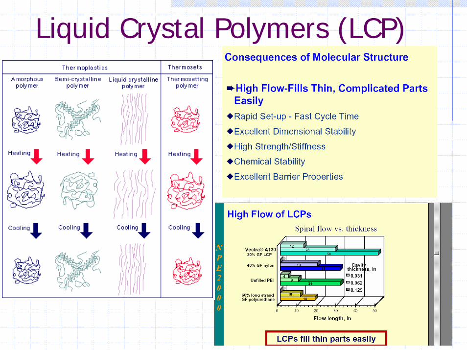
Liquid Crystal Polymers (LCP)
11
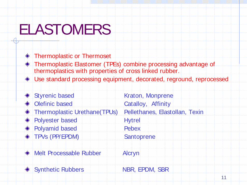
ELASTOMERS
Thermoplastic or ThermosetThermoplastic Elastomer (TPEs) combine processing advantage of thermoplastics with properties of cross linked rubber.Use standard processing equipment, decorated, reground, reprocessed
Styrenic based Kraton, MonpreneOlefinic based Catalloy, AffinityThermoplastic Urethane(TPUs) Pellethanes, Elastollan, TexinPolyester based HytrelPolyamid based PebexTPVs (PP/EPDM) Santoprene
Melt Processable Rubber Alcryn
Synthetic Rubbers NBR, EPDM, SBR
12
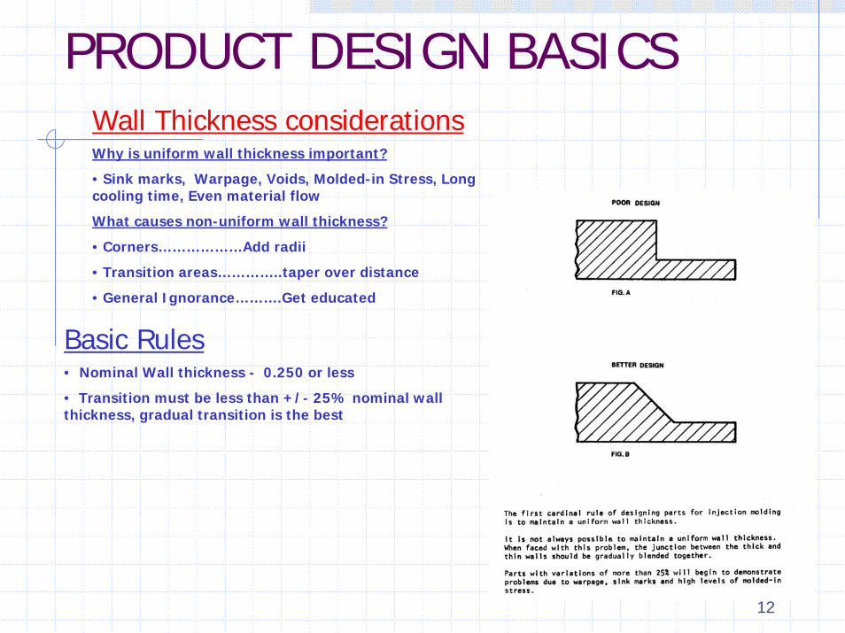
PRODUCT DESIGN BASICSWall Thickness considerationsWhy is uniform wall thickness important?
• Sink marks, Warpage, Voids, Molded-in Stress, Long cooling time, Even material flow
What causes non-uniform wall thickness?
• Corners………………Add radii
• Transition areas…………..taper over distance
• General Ignorance……….Get educated
Basic Rules• Nominal Wall thickness - 0.250 or less
• Transition must be less than +/- 25% nominal wall thickness, gradual transition is the best

13
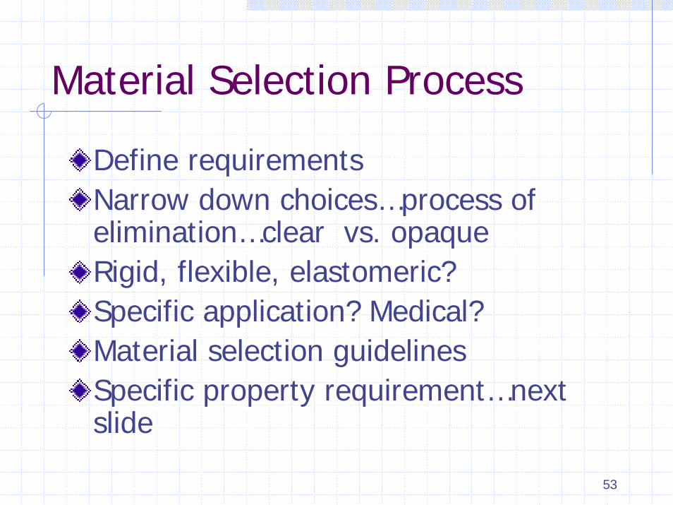
Material Selection Process
Define requirementsNarrow down choices…process of elimination…clear vs. opaqueRigid, flexible, elastomeric?Specific application? Medical?Material selection guidelinesSpecific property requirement…next slide
14
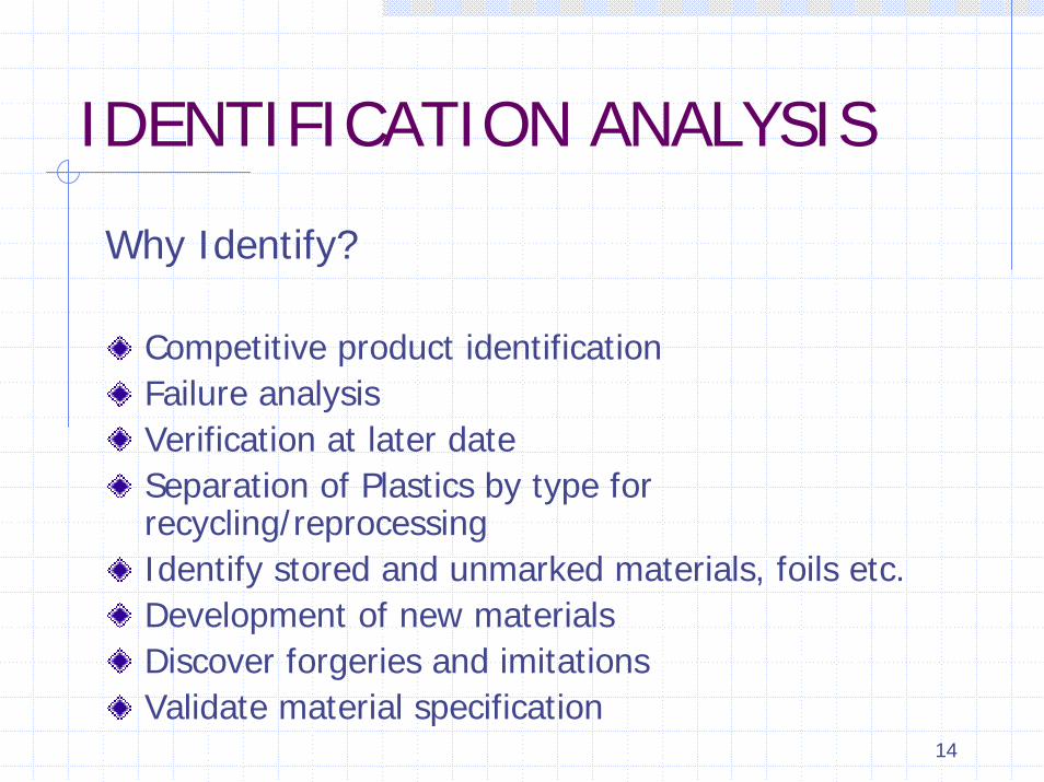
IDENTIFICATION ANALYSIS
Why Identify?
Competitive product identificationFailure analysisVerification at later dateSeparation of Plastics by type for recycling/reprocessingIdentify stored and unmarked materials, foils etc.Development of new materialsDiscover forgeries and imitationsValidate material specification

15ID Chart

16
Injection Molding Machine TypesToggle…………Small machines, Fast, High maintenance, Hydraulic……..Large machines, Slow, more expensiveElectric………..Up to 500 Tons, Accurate, excellent repeatability,
50 to 70 percent less electricity consumption, low maintenance
Injection UnitClamping UnitMachine Specifications…..Tonnage/Shot size
Tons/OzInjection Molding Cycle: Mold Close – Inject – Hold – Cooling – Open – Eject Multi-Material Molding(Coinjection)Reaction Injection Molding(RIM)Liquid Injection Molding(LIM)
Mold Filling (5)Packing (3)Holding (3)Cooling (25)Ejection (2)

17
EXTRUSION
18
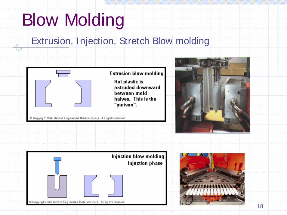
Blow MoldingExtrusion, Injection, Stretch Blow molding
19
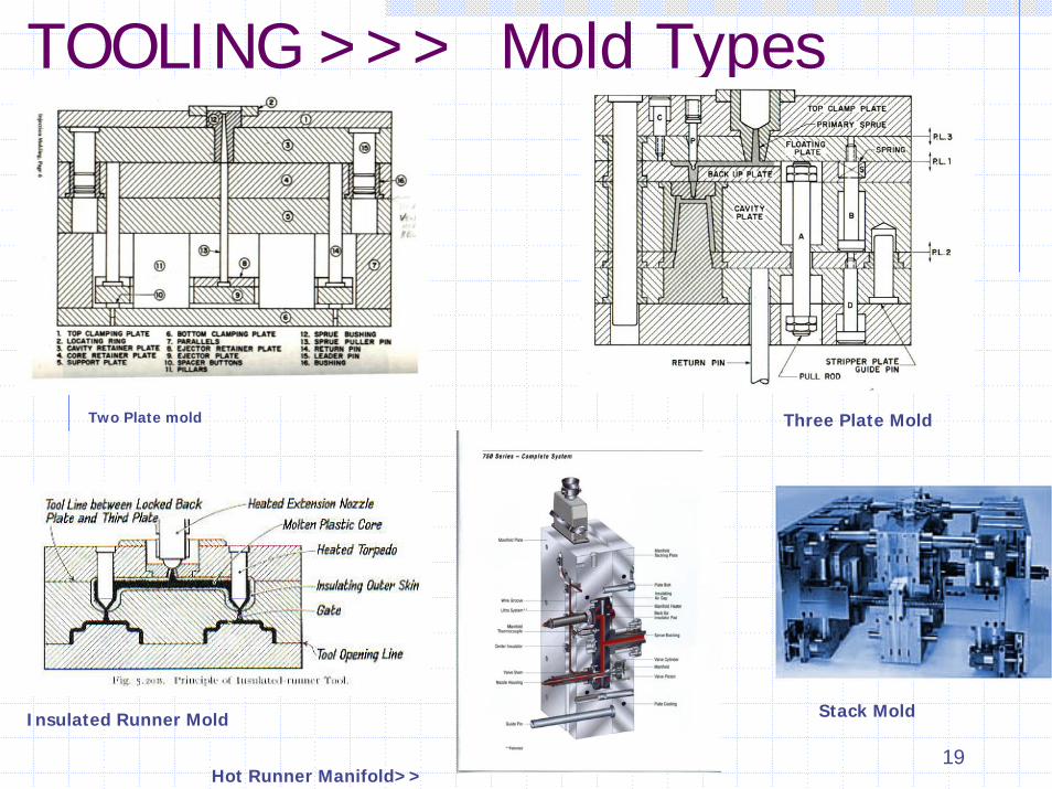
TOOLING >>> Mold Types
Two Plate mold Three Plate Mold
Stack MoldInsulated Runner Mold
Hot Runner Manifold>>

20
SPI Mold Classifications
Class 101 1MM cycles or moreClass 102 Not exceeding 1MMClass 103 Under 500,000 cyclesClass 104 Under 100,000 cyclesClass 105 Not exceeding 500
21
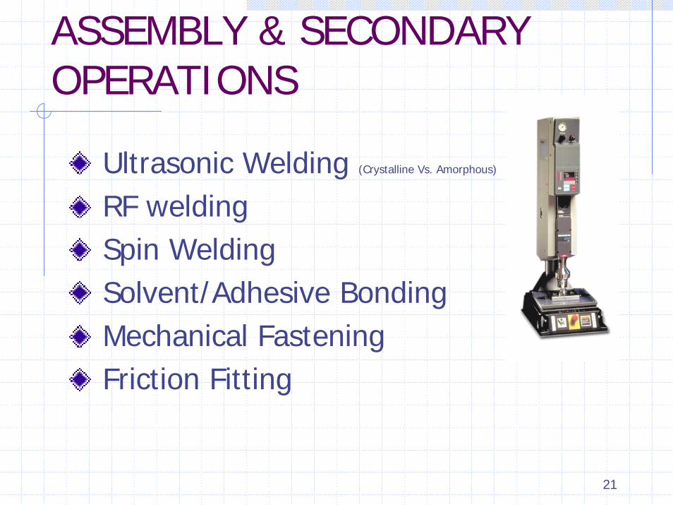
ASSEMBLY & SECONDARY OPERATIONS
Ultrasonic Welding (Crystalline Vs. Amorphous)
RF weldingSpin WeldingSolvent/Adhesive BondingMechanical FasteningFriction Fitting

22
Decorating & Printing
1. In standard open inkwell pad printing, the spatula scoops ink out of the inkwell and over the entire clichéplate surface with the doctor blade lifted off the surface.
2. The pad slide moves to the right as the doctor blade removes excess ink from the cliché.
3. The transfer pad, or tampon, is then pressed against the inked plate and lifted.
4. As the transfer pad (now holding image) moves left toward the object to be printed, new ink is deposited onto the plate.
5. With the new image now slightly tacky, the pad descends to the part, leaves the imprint, and the process is then repeated

23
TESTING & FAILURE ANALYSIS
Mechanical PropertiesThermal PropertiesElectrical PropertiesWeatheringOptical PropertiesMaterial Characterization TestsChemical propertiesFlammabilityFailure Analysis

24
Photoelastic Pattern
25
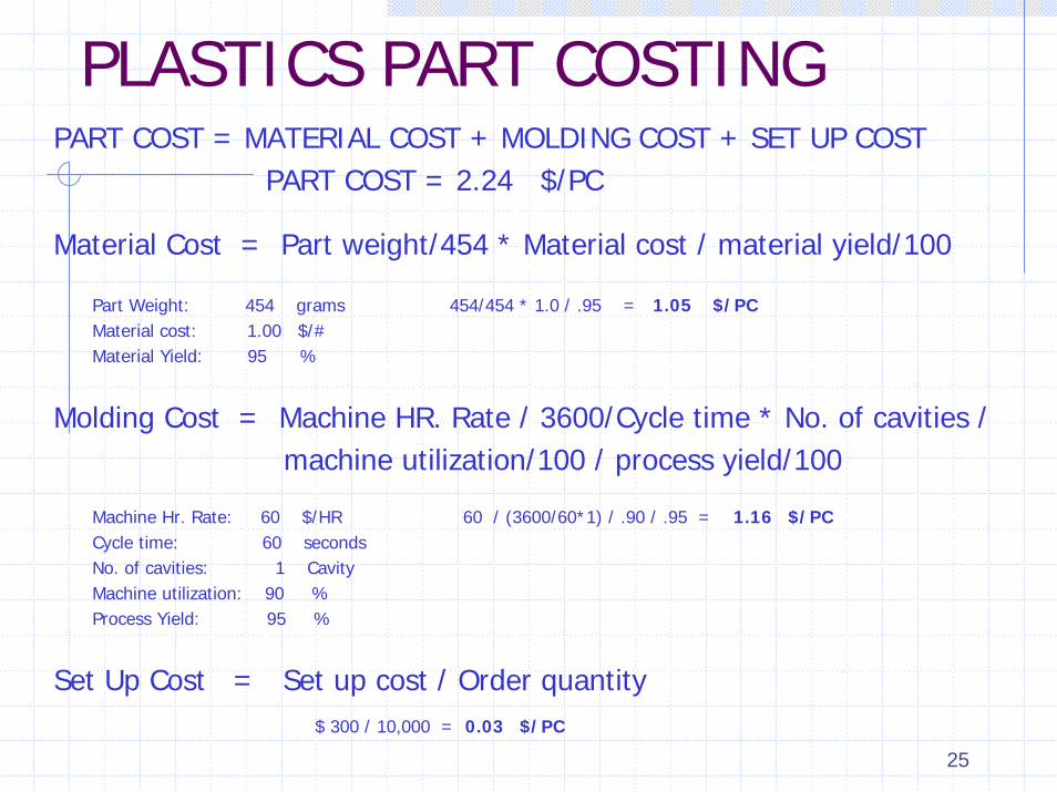
PLASTICS PART COSTINGPART COST = MATERIAL COST + MOLDING COST + SET UP COST
PART COST = 2.24 $/PC
Material Cost = Part weight/454 * Material cost / material yield/100
Part Weight: 454 grams 454/454 * 1.0 / .95 = 1.05 $/PCMaterial cost: 1.00 $/#Material Yield: 95 %
Molding Cost = Machine HR. Rate / 3600/Cycle time * No. of cavities / machine utilization/100 / process yield/100
Machine Hr. Rate: 60 $/HR 60 / (3600/60*1) / .90 / .95 = 1.16 $/PCCycle time: 60 secondsNo. of cavities: 1 Cavity Machine utilization: 90 %Process Yield: 95 %
Set Up Cost = Set up cost / Order quantity $ 300 / 10,000 = 0.03 $/PC

26
Where to Get More InformationBOOKSSPE Book Store, www.4spe.orgIMM Book Club, www.immnet.comHanser Gardner Publications, www.hansergardner.com
SEMINARSUniversity of Massachusetts Lowell Continuing Studies and Corporate Education, Lowell, MAwww.continuinged.uml.edu/plastics
Society of Manufacturing Engineers, www.sme.orgSPE Educational Seminars, www.4spe.orgTechtrax, www.techtrax.net
TRADE PUBLICATIONSInjection Molding Magazine immnet.comPlastics Engineering www.4spe.orgPlastics Technology www.plasticstechnology.comModern Plastics www.modernplas.com
INTERACTIVE TRAINING PROGRAMSPaulson Training Programs, Inc. www.paulson-training.comA. Routsis Associates Inc. www.traininteractive.com

27
Molded-in Stress in Optical Polycarbonate Applications

28
Topics of discussion
Current methods of measuring molded-in stresses in molded polycarbonates & Industry standards.How is this data being used?Pros and Cons of current testing methods.Industries perception – Perceived value or inconclusive?

29
Polycarbonate Solvent stress Analysis
GE Plastics test Method T-77
This test, developed by GE plastics, is used mainly for evaluating residual stress in molded parts. The test can also determine effect of external stress or stresses resulting from molded-in inserts or press-fit items.The combination of two solvents, Methanol and Ethyl Acetate, is used in various proportions. Effect of this mixture on specimen is observed when exposed for specified time period.
30
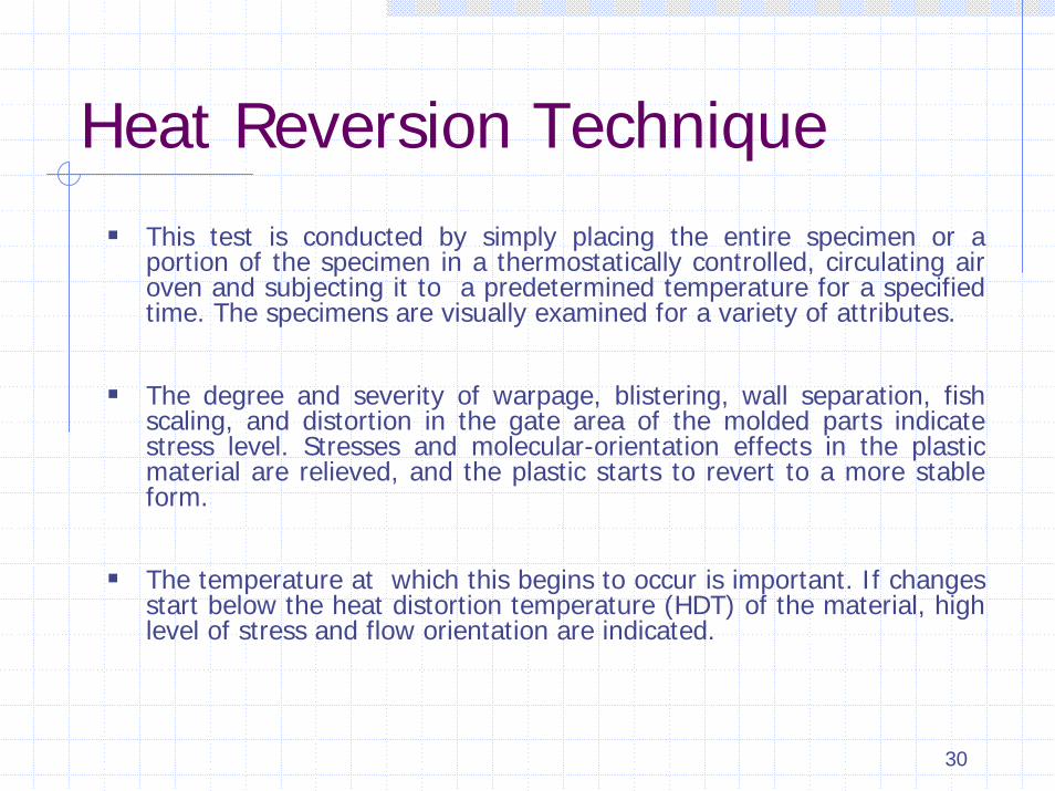
Heat Reversion TechniqueThis test is conducted by simply placing the entire specimen or a portion of the specimen in a thermostatically controlled, circulating air oven and subjecting it to a predetermined temperature for a specified time. The specimens are visually examined for a variety of attributes.
The degree and severity of warpage, blistering, wall separation, fish scaling, and distortion in the gate area of the molded parts indicate stress level. Stresses and molecular-orientation effects in the plastic material are relieved, and the plastic starts to revert to a more stable form.
The temperature at which this begins to occur is important. If changes start below the heat distortion temperature (HDT) of the material, high level of stress and flow orientation are indicated.

31
Principles of PhotoelasticityWhen polarized light passes through a material that is stressed, the light splits into two divergent polarized beams vibrating in different planes (x and y) along the direction of the principal stresses.
This phenomenon, which results in two different indices of refraction, is known as birefringence.
Reference Direction X
Direction of Stress
Light Source
Plane Polarized Light
Y Directionof Stress
Point of Interest

32
Principles of PhotoelasticityBy rotating the second polarizing filter (analyzer), the user can control the amount (intensity) of light allowed to pass through. The components of the two light waves that do pass through at any given angle of analyzer rotation interfere with each other, resulting in a characteristic color spectrum.
Plane Polarized Light
Point of Interest
Retardation
Analyzer

33
How to quantify the results…..
Qualitative…….Visual, Best guess, interpretation variationsQuantitative….reliable, measurable values, ASTM D 4093Manual measurement techniquesEquipment : Polariscope or Polarimeter with compensator and Calibrated wedge

34
Links to articles….
Measuring Residual Stress In Transparent Plasticshttp://www.devicelink.com/mpb/archive/97/01/001.html
Stress Crack Test: Makrolon moldingshttp://plastics.bayer.de/AG/AE/literature/fulltext/index.jsp
Polycarbonate: Molded Part Internal Stresshttp://www.diamondpolymers.com/techcenter/guides/pc_stresstest.pdf

35
PLASTICS FAILURE ANALYSIS AND TESTING
Vishu ShahConsultek

36
Topics Failure Analysis
Why do Plastics parts fail?Reasons behind part failures
Material selection ANALYZING FAILURES – STEPS AND TOOLSDesign CONCURRENT ENGINEERING TO PREVENT FAILURESProcessService Conditions
Types of FailuresMechanicalThermalChemicalEnvironmental
Testing
Mechanical propertiesThermal propertiesElectrical propertiesMelt Index testColor measurementWeathering PropertiesUL Flammability testingMaterial Identification TechniquesEnd Product testing

37
Material SelectionMaterial Selection Pitfalls
• Datasheet interpretation
• Synergistic effects
• Economics
• Supplier Recommendations
• Application checklist

38
Failure resulting from improper material selection

39
DesignMost Common Mistakes in Design of Plastics
• Non-uniform wall thickness
• Sharp corners, lack of radius
• Draft angle considerations
• Lack of Creep considerations
• Direct conversion from other materials

40
ProcessMost Common Process Induced Failures
• Drying of material
• Molded-in stresses
• Knit lines
• Degradation
• Shrinkage voids
• Regrind level
• Contamination

41
Service ConditionsFailures due to:
• “Reasonable” misuse…….Examples
• Use of product beyond its intended lifetime
• Unstable/Unintentional/Unanticipated service condition • Thermal, Chemical, Environmental, Physical, Biological, Mechanical
• Examples of unintentional service…..coffee can lid, cash drawer, one time short service..bags, cups
• Examples of unexpected service……underground animals
• Service conditions beyond reasonable misuse
• Simultaneous application of two stresses operating synergistically

42
Types Of Failures
MechanicalThermalChemicalEnvironmental

43
Failure Analysis Steps & Tools
Visual Analysis…..Knit line, Degradation, Discoloration, User Abuse, Examination under magnifier, Broken surfaceStress analysis, Photoelastic analysis, strain gageSimple tests…..Material IdentificationMechanical testingNondestructive testingAdvance Tests…….FTIR, DSC, TGA Microtoming(microstructuralanalysis), Pyrolysis(Burn out)
44
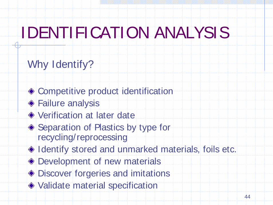
IDENTIFICATION ANALYSIS
Why Identify?
Competitive product identificationFailure analysisVerification at later dateSeparation of Plastics by type for recycling/reprocessingIdentify stored and unmarked materials, foils etc.Development of new materialsDiscover forgeries and imitationsValidate material specification

45ID Chart

46
MELT INDEX TEST
Melt Index test measures the rate of extrusion of thermoplastic material through an orifice of specific length and diameter under prescribed conditions of temperature and pressure.Melt Index value is reported in grams per 10 minutes for specific condition.Distinguishes between the different grades of a polymer.
47
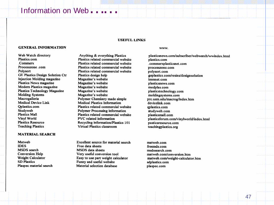
Information on Web……

48
Local Failure Analysis Laboratories
KARS' ADVANCED MATERIALS, INC.
7271-CD Garden Grove Blvd.Garden Grove, CA 92841
(714) 892-8987 Fax: (714) 894-0225 [email protected]
Seal Laboratories Inc.250 N. Nash Street, El Segundo CA 90245 PH: 310-322-2011www.seallabs.com
CRT Laboratories, Inc.1680 N. Main Street, Orange, CA 92867 PH: 800-597-LABSwww.crtlabs.com
49
Plastics Identification & Material Selection Process
Vishu ShahConsultek

50
IDENTIFICATION ANALYSIS
Why Identify?
Competitive product identificationFailure analysisVerification at later dateSeparation of Plastics by type for recycling/reprocessingIdentify stored and unmarked materials, foils etc.Development of new materialsDiscover forgeries and imitationsValidate material specification

51
SIMPLE METHODS OF IDENTIFICATION
Useful for identifying basic polymer and differentiating between the different types of polymers within the same family.Requires no special equipment or in-depth knowledge of analytical chemistrySimple step by step identification procedure using flow chart

52
53
Material Selection Process
Define requirementsNarrow down choices…process of elimination…clear vs. opaqueRigid, flexible, elastomeric?Specific application? Medical?Material selection guidelinesSpecific property requirement…next slide

54
Identifying Application Requirements
Physical PropertiesSpecific GravityMold ShrinkageRheology
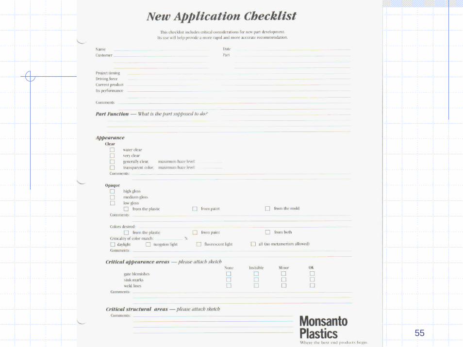
Mechanical PropertiesTensile StrengthTensile Modulus (Stiffness-Resistance to bending)Tensile Elongation/DuctilityImpact strengthFatigue Endurance ( Resistance to high frequency cyclic loading)Creep resistance (Resistance to long-term deformation under load)Thermal PropertiesDeflection Temperature Under Load (DTUL,HDT)Thermal ConductivityThermal expansion coefficientContinuous Use Temperature (Relative thermal Index)Regulatory PerformanceFlammability (UL 94)High Voltage Arc TrackingFDA
Source: GE Plastics
55

56
57
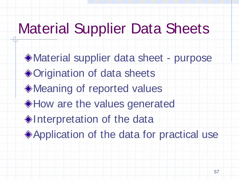
Material Supplier Data Sheets
Material supplier data sheet - purposeOrigination of data sheetsMeaning of reported valuesHow are the values generatedInterpretation of the dataApplication of the data for practical use

58
Purpose of a data Sheet
Compare property values of different plastics materials (Tensile strength of nylon vs. Polystyrene, Impact strength of ABS vs. Polycarbonate)Quality control guidelines for material manufacturersPurchasing/Material specificationsInitial screening of various materials

59
Other Important Considerations
CostProduct designToolingShrinkageSecondary OperationsAssemblyInterpreting Data SheetsPrototyping and Testing

60
Material Selection using Web
Matweb www.matweb.comIdes www.freemds.comPlaspec www.plaspec.com
Consultek www.consultekusa.com

61
Plastics Part Design for Injection Molding
Vishu Shah

62
CURRICULUM
Polymer Chemistry Basics and Material Selection ProcessPlastics Material Identification TechniquesConcurrent Engineering, Plastics Part Design Process overviewManufacturing Considerations – Design For MoldingManufacturing Considerations – Design For MoldingBasic Part DesignBasic Part DesignBasic Part Design, Prototyping and TestingDesign For Assembly and review of assembly techniquesTooling Considerations

63
CONCURRENT ENGINEERING

64
Manufacturing
Considerations For
Injection Molded Plastic Parts
Design For Manufacturing/Molding (DFM)
•Mold filling
•Weld lines / Knit lines
•Shrinkage
•Ejection
Title DFM
65
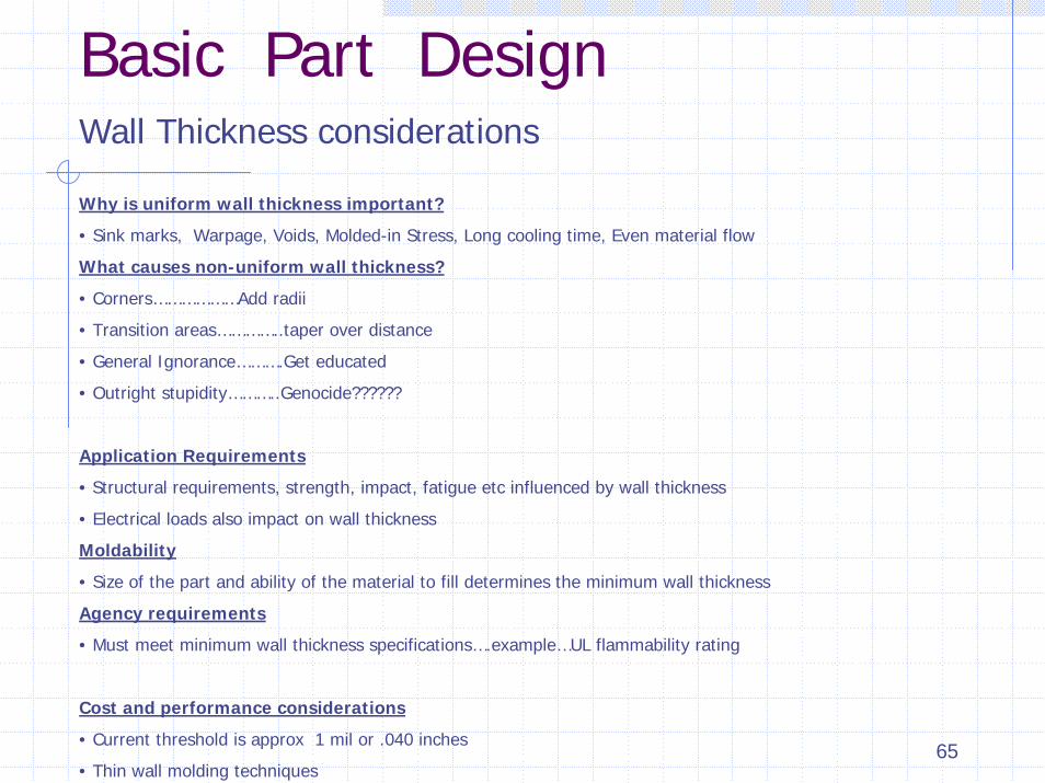
Basic Part DesignWall Thickness considerations
Why is uniform wall thickness important?
• Sink marks, Warpage, Voids, Molded-in Stress, Long cooling time, Even material flow
What causes non-uniform wall thickness?
• Corners………………Add radii
• Transition areas…………..taper over distance
• General Ignorance……….Get educated
• Outright stupidity………..Genocide??????
Application Requirements
• Structural requirements, strength, impact, fatigue etc influenced by wall thickness
• Electrical loads also impact on wall thickness
Moldability
• Size of the part and ability of the material to fill determines the minimum wall thickness
Agency requirements
• Must meet minimum wall thickness specifications….example…UL flammability rating
Cost and performance considerations
• Current threshold is approx 1 mil or .040 inches
• Thin wall molding techniques
66
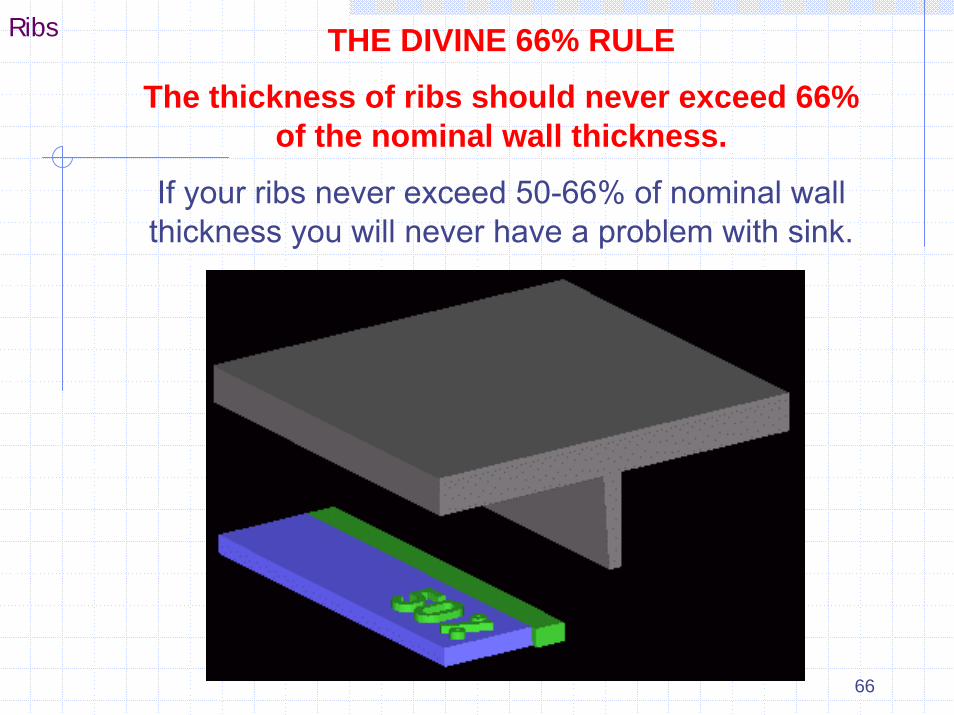
Ribs THE DIVINE 66% RULE
The thickness of ribs should never exceed 66% of the nominal wall thickness.
If your ribs never exceed 50-66% of nominal wall thickness you will never have a problem with sink.

67
Boss There are two primary moldability factors to consider when designing bosses.1. Avoiding sink 2. Ejection feasibility
Note that the the boss wall is 66% of the nominal wall thickness. The core pin up the center penetrates 50-66% of the way through the
nominal wall.
Note the circular sink marks
created by the failure to properly core out the
boss
68
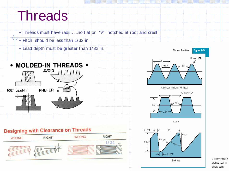
Threads• Threads must have radii……no flat or “V” notched at root and crest
• Pitch should be less than 1/32 in.
• Lead depth must be greater than 1/32 in.
1/32
69
PROTOTYPING TECHNIQUES
Hand fabrication and machiningPrinting (Solid Object printer)Stereo Lithography (SLA)Selective Laser sintering (SLS)Part Casting techniquesSoft toolingHard tooling

70
All about RPwww.cc.utah.edu/~asn8200/rapid.html
WELCOME TO THE RAPID PROTOTYPING HOME PAGE
"Your link to the world of Rapid Prototyping" since July, 1995
Last update: February 13, 2002 . This document is updated frequently in an effort to keep up with the latest developments in the fast paced field of Rapid Prototyping (aka Desktop Manufacturing, Solid Freeform Fabrication, or Layered Manufacturing). The sign indicates items that have been added since the last update.
Also visit: The Rapid Tooling Home Page.
TABLE OF CONTENTS
Commercial Rapid Prototyping SystemsConcept ModelersResellers of Concept Modelers and RP SystemsCommercial Service Providers ConsultantsAcademia and ResearchPublications and ConferencesMagazine ArticlesBiomedical uses of Rapid PrototypingArt via Rapid PrototypingSoftware for the Rapid Prototyping MarketProfessional Associations Other Valuable Resources

71
How can one design a part so that tooling is:
• Easy to build
• Cost effective
• Efficient in terms of cycle time and operation
• Less complex
• Long lasting
Tooling Considerations
72
Design For Assembly (DFA)
Advantage>>>>>>PLASTICS
• Variety of fastening methods………Press fit, Snap fit, Bonding, Welding
• Ability to manufacture complex geometries
• Ability to use various manufacturing processes
• lower cost assembly techniques
• Automation
• No post secondary operations (Such as deburring, finishing)
• Reduce number of components
• Lower overall product cost

73
Press Fit Assembly
Material Considerations• Ductile materials preferred
• Low stress level desired (Calculate)
• Use materials with similar coefficient of thermal expansion
Design Considerations• Use interference limit graphs from material suppliers
• Draft angle as small as possible
• Smooth Vs. knurled or splined shaft

74
Part Design to Enhance Flow and Shape
Design part with ample curve to enhance flow
Design part with minimum number of projections and cored sections
75
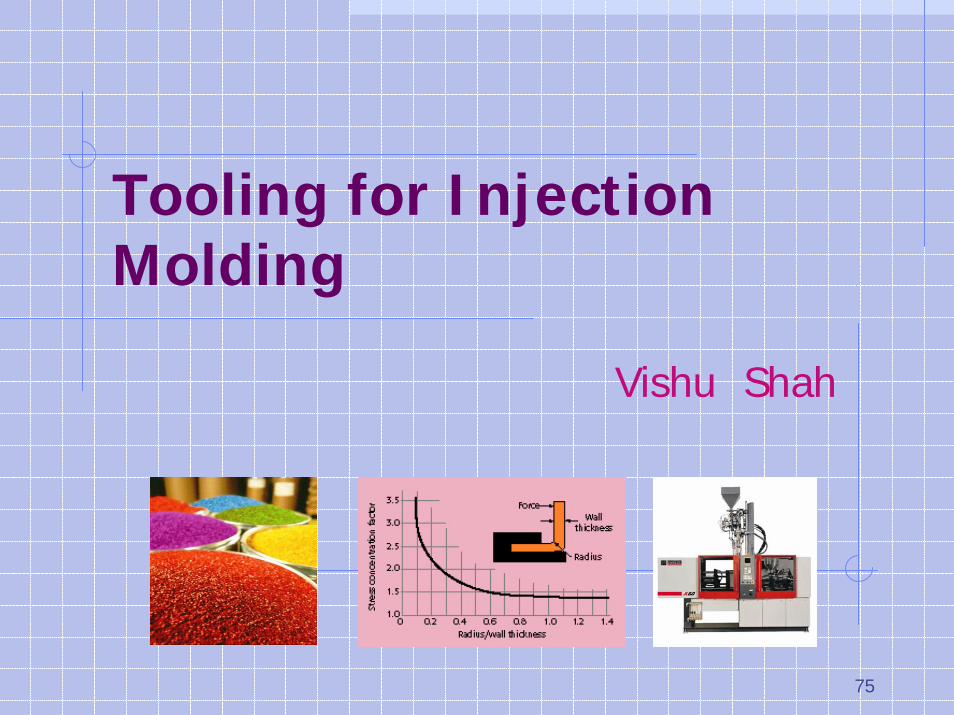
Tooling for Injection Molding
Vishu Shah

76
CurriculumPolymer Chemistry - Plastics materialsInjection Molding processTooling Considerations
Mold Metallurgy, Runners, Gates, Sprue bushing, Sprue pullersMold Design and Simulation softwareTooling considerations
Cooling, VentingTooling Considerations
Draft angles, Shrinkage, Mold polishing, Tool surface enhancementHot runner systemsRapid tooling techniques

77
Screw - Barrel – Check Ring
Screw Material
• Nitrided
• D2
Barrel materials• Nitrided
• Bimetallic

78
Types Of Molds
Two plate moldThree Plate moldInsulated hot runner moldHot runner moldStack mold

79
Hot Runner (Runnerless) Molds
In the hot runner mold, the runners are kept hot in order to keep the molten plastic in a fluid state at all times. This is a “Runnerless” molding process and hence the name. Hot runner molds are similar to the three plate molds, except that the runner section of the mold is not opened during the cycle. The heated runner plate (Manifold) is kept insulated from the rest of the relatively cooler mold.
• No runner to separate from the molded parts
• No runners to either dispose of or regrind and reprocess
• Less possibility of contamination
• Hot drops carry consistent heat at processing temperature directly into the cavity
• Lower cycle (cooling) time – cooling time not runner dependent
• No robotics (or automation) needed for runner removal
• Possibly lower injection pressure
• No sprue/runner sticking problems
• Cleaner molding environment
80
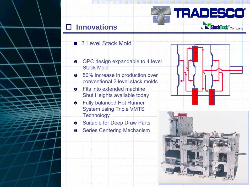
■ 3 Level Stack Mold
QPC design expandable to 4 level Stack Mold50% Increase in production over conventional 2 level stack moldsFits into extended machine Shut Heights available todayFully balanced Hot Runner System using Triple VMTS TechnologySuitable for Deep Draw PartsSeries Centering Mechanism
VMTS
VMTS
VMTS
Innovations ®A Company

81
Major categories of applications in molds
• Mold Cavity and Core unit components
• Mold base plates
• Special function components (Slides, gibs, wear plates)
Material selection considerations
• Type of plastics to be molded….abrasive, corrosive etc
• Number of parts to be molded
• Surface finish of molded parts
• Cavity design requirements…metal to metal contacts etc.
• Method of cavity forming…Machining requirements
• Method of heat treating

82
Recommended runner sizes

83
Types of Gates
Sprue Gate….used on large single cavity parts, cold slug issuesEdge gate…Large surfaces, thin wall, keep parts attachedFan gate…minimize surface imperfections, reduce stressSub gate…(Tunnel gate)…AutomationDiaphragm gate…round part, avoid weld lineFlash gate…similar to fan gate..much wider, low warpageRing gate…hollow tubular parts, helps with core shift Tab gate…stress free part and optical clarity…acrylic lensSub gate into ejector pin…no gate marks

84
Gating Considerations
Land Length:0.040 max. long land length creates excessive pressure drop, part filling problem
Steel safe: Start small and increase as needed
Gate size: Larger the gate..lower the stress
Gate placement: Cosmetic issues, Jetting

85
Sizing VentsWidth: As wide as possible
Minimum 0.125
Depth: 0.0005 to 0.002
Ask material supplier
Land: As short as possible
Relief slot (vent channel):
Minimum 20 x depth
Amount: 30% of the perimeter of the part
VENT THE RUNNER….
YOU CAN’T HAVE TOO MUCH VENTING!!!!!
86
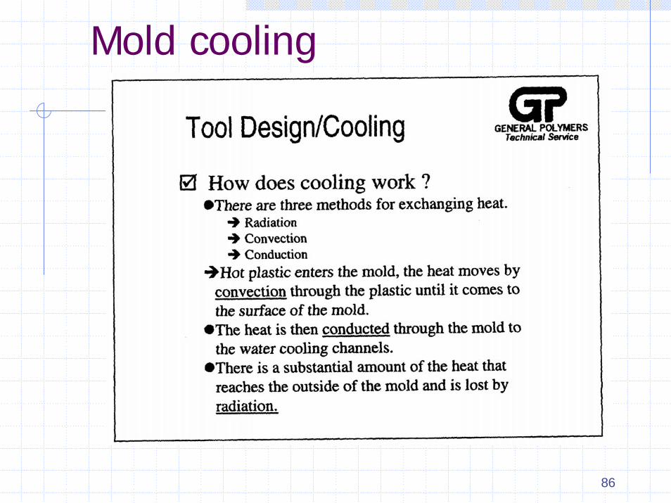
Mold cooling

87
Flow rate
Minimum flow rate (GPM)For good Reynolds Number (turbulent flow)……..
Minimum GPM = 3.5 x pipe I.D.
Example:
• Ten ½” lines in parallel
• All equal lengths into common manifolds
Min. GPM Required = ½ x 3.5 x 10 = 17.5*
* Does not take into account heat load required to remove total heat from Plastic material.
Alternate Rule of Thumb: 7/16’ Diameter Waterline requires 1.5 GPM to achieve turbulent flow.

88
Heat Pipes

89
Shrinkage - Crystalline vs. Amorphous material
Why do crystalline material have greater shrinkage than amorphous materials?
As the melt cools and changes from liquid to solid, there is a substantial decrease in specific volume in crystalline materials due to the crystalline structure of the polymer and therefore greater shrinkage.

90
PROTOTYPING TECHNIQUESHand fabrication and machiningPrinting (Solid Object printer) 3D Systems
Stereo Lithography (SLA) 3D Systems
Selective Laser sintering (SLS) 3D systems
Fused Deposition Modeling (FDM)Stratasys
Part Casting techniquesSoft tooling (Machining, Keltool, SLS process)
Hard tooling

91
Scientific Injection Molding
Vishu Shah

92
What is Scientific Injection Molding?
Science of Injection moldingEverything substantiated by scientific dataScientific approach to establishing molding variablesUnderstanding of four critical components
MaterialPart DesignToolingProcessing
Every decision Must be backed by scientific data
93
CURRICULUM
Polymer Chemistry Basics Part Design FundamentalsOverview of Basic Injection Molding process Drying, Material mixing, Coloring, Regrind UsageMajor Process variablesDecouple Molding, Universal Set Up Sheet Tooling Considerations, Venting, Cooling, EjectionCycle Time Optimization,and Trouble shooting techniquesMold Flow Analysis, Productivity ImprovementsModern Injection Molding Operation

94
Injection Molding…..simplifiedInjection molding is a dynamic, non-linear process consisting of four sequential stages: plastication, filling, packing and ejection. In its simplest form an injection molding machine can be regarded as a large hydraulic pump, which, by virtue of a hydraulically controlled ram: transforms solid thermoplastic pellets into molten polymer (plastication), injects molten polymer into the mold cavity (filling), and pressurizes the cavity during polymer solidification (packing). Once the molded part has taken its final shape and allowed to cool, the mold is opened (ejection) and the process repeated
Source: Moldflow article
3 M’s and 3 F’sMaterial is MELTED………MIXED….&………MOVED
FLOWED (INJECTED)………FORMED………&………FROZEN (COOLED)Source: GE Plastics)
95
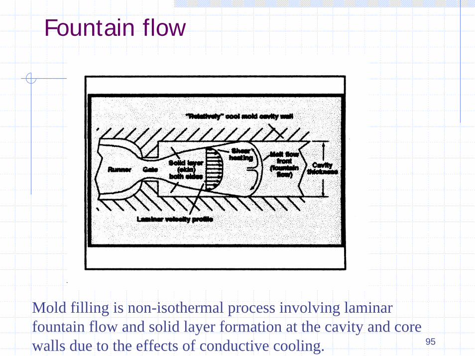
Fountain flow
Mold filling is non-isothermal process involving laminar fountain flow and solid layer formation at the cavity and core walls due to the effects of conductive cooling.

96
Materials DryingWhy do we need to dry Plastics Materials?All Plastics, when exposed to atmosphere, will pick up moisture to a certain degree depending upon the humidity antype of the polymer.
Hygroscopic Non Hygroscopic
Polymers with high affinity for moisture Polymers with very little or no affinity for moisture
Moisture is absorbed into the pellet over time until equilibrium is reached
No absorption of moisture into the pellet. May pick up surface moisture.
Nylon, ABS Polystyrene
Polycarbonate Polyethylene
Polyester PVC, Polypropylene
Polyurethane AcetalDesiccant Dryer Hot Air Dryer

97
L/D and Compression Ratio
Compression Ratio
GP Materials 3:1
PVC 1.4:1
Acetal 4:1
98
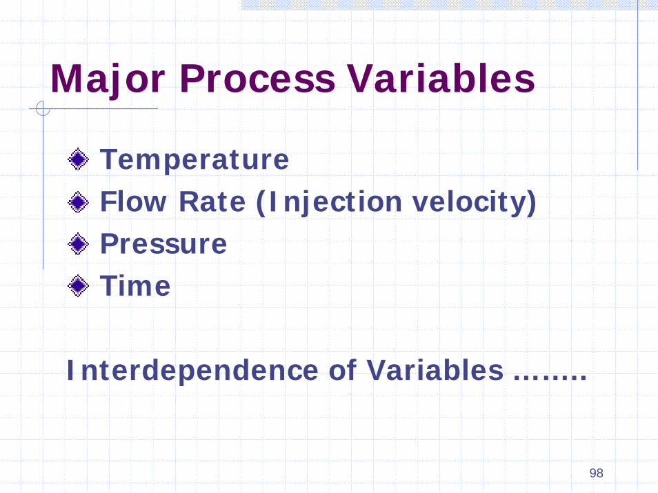
Major Process Variables
TemperatureFlow Rate (Injection velocity)PressureTime
Interdependence of Variables ……..

99
Flow rateAll Plastics exhibit Non-Newtonian behavior………
Newtonian: Shear rate has no effect on viscosity…….Water
Non –Newtonian: Viscosity varies with shear rate
Plastics material’s viscosity decreases as shear rate increases
WHY IS THIS IMPORTANT??????
• Screw speed…….Lower viscosity at higher screw rpm
• Injection speed…..Flows easier with higher injection speed
Flow rate ( Injection speed, velocity) = Time in seconds, measured from start of injection to transfer to pack/hold

100
Hydraulic pressure Vs. Plastic pressure
Hydraulic pressure : measure of how much force a machine can generate against the ram
Plastic (Melt) Pressure: Pressure generated in the nozzle of a molding machine usually derived from the intensification ratio of the machine
Cavity Pressure: Actual pressure in the cavity (Mold).

101
Cooling timeMold cooling accounts for more than two-thirds of the total cycle time in the production of injection molded thermoplastic parts
Cooling time is a function of :
• mold wall temperature
• melt temperature
• material properties
• part wall thickness

102
Decoupled molding
Conventional Molding
Injection ------ Pack -------Hold
Decouple Molding
DecoupleInjection -----------------------------------------------------Pack and Hold
FromFill -----------------------------------------------------------Pack and Hold
95% ------------------------------------------------------- 5%
103
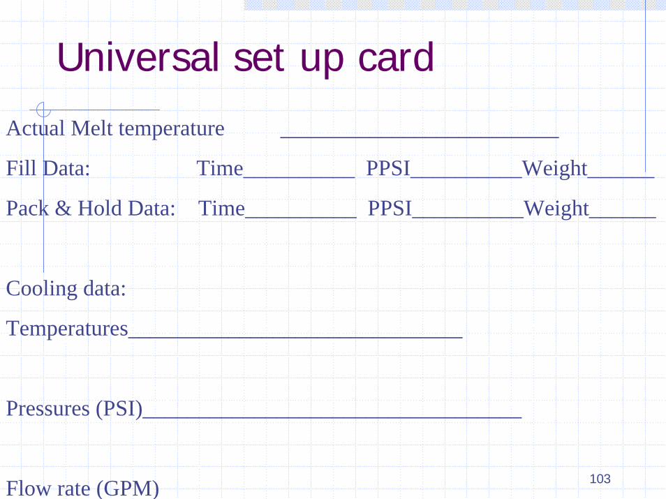
Universal set up card
Actual Melt temperature _________________________
Fill Data: Time__________ PPSI__________Weight______
Pack & Hold Data: Time__________ PPSI__________Weight______
Cooling data:
Temperatures______________________________
Pressures (PSI)__________________________________
Flow rate (GPM)

104
The Universal Setup Card
Mold number, number of shots to date, part name, customer, date, molder's name, and any other information your plant may require. Fill time for a part 95 to 99 percent full. Weight and picture of part 95 to 99 percent full. Transfer volume, transfer position, or cavity pressure (time and hydraulic pressure transfer modes are not recommended). Nozzle melt pressure range for different lots at transfer volume, position, or cavity pressure. First stage set melt pressure (nozzle); this is first stage set pressure times the intensification ratio. Cycle time. Quoted cycle time(s). Gate seal time. Pack and hold time. Pack and hold melt pressure. Shot size in volume. Mold temperature, cooling channel map. Water flow diagram, with gallons/minute of each channel, temperature of water in and out, and water pressure in and out. Screw run time (average). Mold open and closed time, cure time, or cooling times. Melt temperature via hot probe. Nozzle tip length, diameter, land length, radius, and type. Hydraulic pressure vs. time response curve. Cavity pressure integral at the gate and end of fill.

105
Automation in Injection Molding
Tooling………….Subgates, Hot Runners
Part separators
Regrind feedback
Robotics
“Lights Out” Molding

107
Topics
• What is “MICROMOLDING”
• Markets and applications for micromolding
• Machines for micromolding
• Materials for micromolding
• Tooling for Micromolding
• Part Extraction challenges
• Part Inspection
• What next?
108
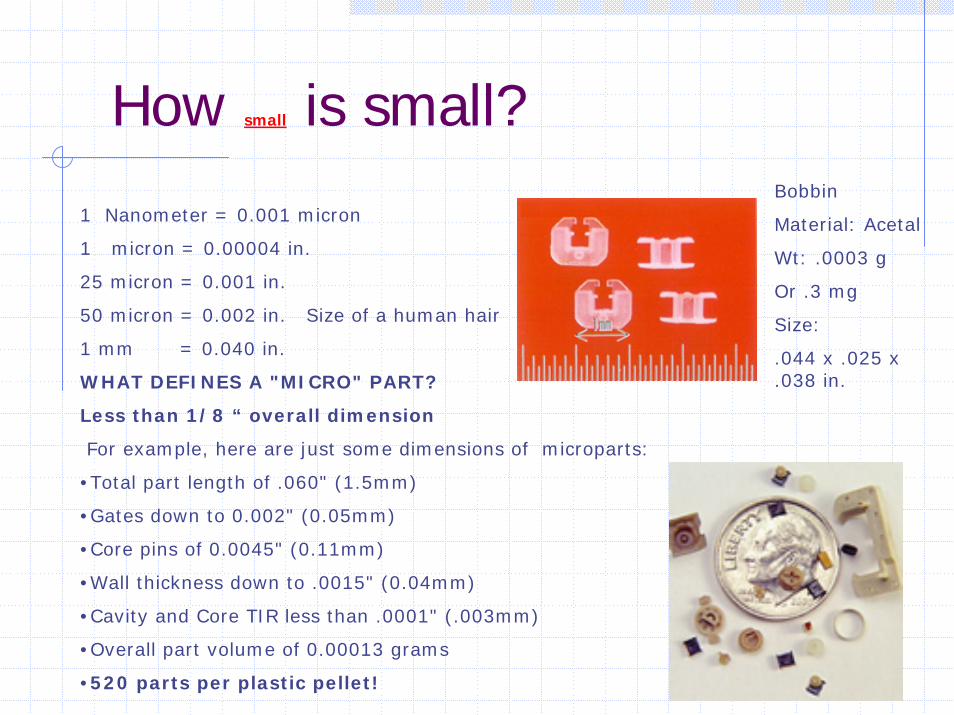
How small is small?
1 Nanometer = 0.001 micron
1 micron = 0.00004 in.
25 micron = 0.001 in.
50 micron = 0.002 in. Size of a human hair
1 mm = 0.040 in.
WHAT DEFINES A "MICRO" PART?
Less than 1/8 “ overall dimension
For example, here are just some dimensions of microparts:
•Total part length of .060" (1.5mm)
•Gates down to 0.002" (0.05mm)
•Core pins of 0.0045" (0.11mm)
•Wall thickness down to .0015" (0.04mm)
•Cavity and Core TIR less than .0001" (.003mm)
•Overall part volume of 0.00013 grams
•520 parts per plastic pellet!
Bobbin
Material: Acetal
Wt: .0003 g
Or .3 mg
Size:
.044 x .025 x
.038 in.

109
Markets and applications for micromolding
Microdrive Systems and Control
Potentiometer Gear
Material: PPAPart weight: 0.0008 g AcetalStepper Motor axle for Watches
Gears

110
Injection Molding Machines for Micromolding
Typical concerns…….
• Material Plasticizing (Plastification)
• Material feeding
• Consistent shot size using standard check ring (reproducibility)
• Material freezing due to extremely small mass
• Shot size generally too large for micro parts
• Material degradation from long residence time
• Melt homogenization
• Static electricity Issues

111
Injection Molding machine designed specifically for Micromolding
Clean room Module
Optical inspection module
Ionization module
Part extraction (Handling) module
Packaging Module

112
Materials for Micromolding
• LCP (Liquid Crystal polymers)
• Acetal
• Polyester
• Polycarbonate
• PEEK
• Glass and Mineral filled compounds adds to the rigidity and stability
• Hygroscopic materials like Nylons are not suitable for micromolding since they change size making it difficult to hold close tolerances

113
Tooling for Micromolding
Challenges in micro mold construction
• Physical limitation to how small one can cut or burn something, established by the geometric characteristics of the feature being formed
• Shear strength of the steel can not resist the pressures exerted by cutting head or in case of EDM surface finish is eroded beyond acceptable level
• Mechanical, thermal and chemical properties of the material being formed are affected
114
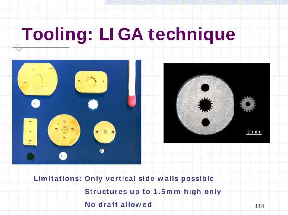
Tooling: LIGA technique
Limitations: Only vertical side walls possible
Structures up to 1.5mm high only
No draft allowed

115
Part Extraction Material handling and packaging
• parts too light to fall out of the mold
• Static electricity issue
• Special robotics and vacuum extraction into small tubes
• “ Reel to Reel” methods such as one used in semi conductor industry
• Assembler unwilling to pick parts one at a time out of a plastic bag
• Bowl fed or vibratory automated assembly systems tend to jam up

116
Part inspectionVideo measuring system
OGP SMARTSCOPEResolution: 0.00025 mm (0.00001”) Standard
0.00001 mm (0.000004”) optional
SEEBREZ 6 x 6Resolution: 0.0005 mm (0.00002”) STD
0.00001 mm (0.00001”) OPT
Quality control solutions Inc.

117
Future of Micromolding
What comes first?…….. Chicken or the Egg???
How big is the market for micromolded parts?
Nano Technology…..Are we there yet?
(1 nanometer = one millionth of a mm or .001 micron)
• New territory for both molder and mold maker
• Lots of trial and error
• Propitiatory technology and expertise developed
• Prepare to spend R & D money and time

118
Molders specializing in Micromolding
ALC Precision (American Laubsher Corp.) NY www.alcprecision.com
Accumold, IA www.accu-mold.com
Micromold, Inc. CA www.micromoldinc.com
Makuta technics, IN www.makuta.com
Precimold Inc. Canada www.precimold.com
Rolla AG, Switzerland www.rolla.ch
American precision Products, AL www.injection-moldings.com
Sovrin Plastics, UK www.sovrin.co.uk
Stack Plastics, CA www.stackplastics.com
Micro Precision Products, CA www.microprecisionproducts.com
Stamm, Switzerland www.stamm.ch

119
Energy Efficient Injection Molding Operation
_______________________________________________________Babu Joseph
Edison
Vishu Shah
ConsultekApril 17, 2003

120
Energy Efficiency
• EFFICIENCY - KWH / KG OF POLYSTYRENE
• 1 KWH / KG = 45.4 KWH / 100 POUNDS
HYDRAULICFIXED V.V / V.S
KWH / KG 0.82 TO 1.25 0.45 TO 0.65
SEMIHYDRAULICHYBRIDS / PARTIAL
ELECTRICS
KWH / KG 0.4 TO 0.6
ALL ELECTRICS 0.2 KWH / KG

121
All Electric Molding Machines
• Technology developed in early 1980 in Japan
• Introduced in USA by Milacron in 1985 at NPE
• Initially available in 50 to 150 tons sizes only
• Today up to 2000 ton all-electric machines available
• Term All-Electric implies use of servomotors on both clamp and injection end
• 10 to 20% higher in cost
• Over 30 machine manufacturers offer all-electric machines
• #1 advantage…..Energy Savings

122
All Electric Molding MachinesEnergy savings form 25% to 60%Repeatability, Accuracy, ConsistencyNo hydraulic oil…cleanNo cooling water costQuietLow maintenance
Higher costTorque related issues….Long Hold times…PVCUnscrewing molds?Core Pulls?

123
Side by Side Comparison
Electric Hybrid Toggle/Hydraulic
Energy Best Better Good/PoorAccuracy/Repeatability
Highest High PoorCleanliness Excellent OK poorNoise Low Medium HighMaintenance Low??? Medium HighUse of existing molds
Low adaptability
Easy Easy
Cost High Medium Low

124
Energy savings With Variable Speed Drives
According to Plastics Technology, the hydraulic pump-motor(s) account for 80% of the total energy usage on an injection molding machine.
Even during periods of low hydraulic demand a maximum fixed-volume flow is produced. An example of the wasted energy at low demands is during the cooling stage of the cycle. During this cooling stage of the cycle, the motor(s) only need 20% rpm. The fixed-speed system wastes considerable amounts of energy by making inefficient use of the hydraulic pump-motor(s).
The motor conversion, from fixed-speed to variable-speed, enables the open loop injection molding process to be dependent on the demand for hydraulic fluid power. In return, there is a reduction in the use of kilowatt (kW) energy.
The basic concept of the system is simple: if the machine does not need the oil, don't pump it in the first place.
125
Energy savings with Auxiliary Equipment
Auxiliary equipment account for 20% of the total energyconsumption
• Dryers
• Grinders
• Mold heaters
• Chillers
• Water Management

126
Energy Savings Measures• Use of hot return air for desiccant regeneration• Example…Moton Luxor line of Dryers
• Use of sensors and controls • Lower drying temperature when not in use
• Honeycomb rotary bed• Crystallized molecular sieves baked on to drying wheel
• Efficient moisture absorption
• Low air pressure (smaller bower)
• Faster drying time
• No dust
• Low pressure dryer (Vacuum dryer)• At low pressure boiling point drops to 133° F
• Low temperature and vacuum removes moisture faster
• Compressed air – no desiccant dryer • Uses hot and compressed air to remove moisture
• No regeneration heaters Cactus dryer

127
Granulators• Shut-down method (Watt Wattcher From IMS co.)
• Voltage reduction method (Performance Controller\MPG)
• RPM reduction
50% reduction in Power consumption
128
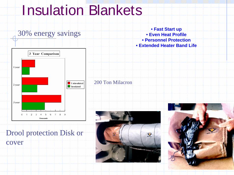
Insulation Blankets• Fast Start up
• Even Heat Profile• Personnel Protection
• Extended Heater Band Life
30% energy savings
200 Ton Milacron
Drool protection Disk or cover

129
Common Sense Approach
• Hot Runners Molds
• Long hold times……Gate freeze studies
• Multiple ejection
• Parts on the floor
• Material on the floor
• Insulated Dryer hoppers
• Leaky Dryer and air Hose
• Oil leaks
• End of jobs….turn off power

130
Gas Assist and Microcellular (MuCell®) Molding Process
Vishu Shah
Consultek

131
What is Gas Assist Injection Molding?
Gas Assist injection molding is a process enhancement to conventional injection molding, involving the injection of high pressure nitrogen gas into the resin melt stream immediately after injection of the resin. The intent is not to cause mixture of nitrogen and resin, but for the nitrogen to displace resin in gas channels and thicker sections of the molded product. The process is a high speed, low pressure injection method, enabled by short shooting the tool, and completing the resin filling phase by nitrogen gas, at a much lower pressures as compared to convention injection molding.
132
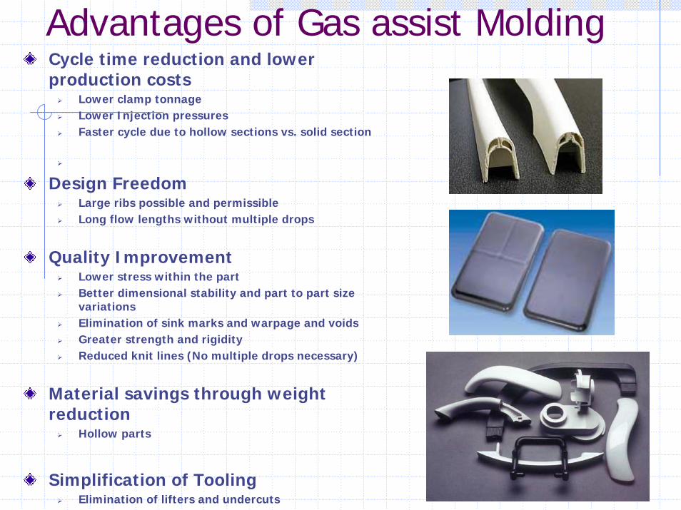
Advantages of Gas assist MoldingCycle time reduction and lower production costs
Lower clamp tonnageLower Injection pressuresFaster cycle due to hollow sections vs. solid section
Design FreedomLarge ribs possible and permissibleLong flow lengths without multiple drops
Quality ImprovementLower stress within the partBetter dimensional stability and part to part size variationsElimination of sink marks and warpage and voidsGreater strength and rigidityReduced knit lines (No multiple drops necessary)
Material savings through weight reduction
Hollow parts
Simplification of ToolingElimination of lifters and undercuts

133
Gas Assist Process Basics
Short-shot molding. A process in which certain features such as ribs or thick walls are cored out with gas in an otherwise solid molded part. This process gets its name from the method of only partially filling the cavity during the polymer injection phase of the cycle and then relying on the gas injection phase to fill out the remainder of the cavity with the material the gas bubble is displacing from the core.
Full-shot molding. A process in which the mold is completely filled during the plastic injection phase. Gas is introduced into the cavity in this case only to provide local packing and to compensate for the effects of polymer volumetric shrinkage as the part cools.
Hollow molding. A process in which all or nearly all of the part is cored out by the gas, in effect making the part itself the gas channel. This is the method most often used to make parts with large cross sections such as rods, tubes, and handles. Source: MD&DI April 1998 article

134
Gas Delivery System
Nitrogen Bottles
Nitrogen Generators
Central Nitrogen Systems

135
Part Design for Gas Assist
• Sizing of gas channels• Gas channel layout• Location of gas injection point(s)
136
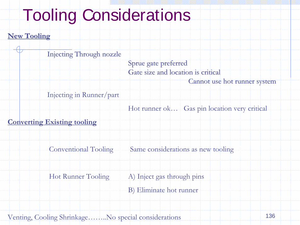
Tooling ConsiderationsNew ToolingNew Tooling
Injecting Through nozzleInjecting Through nozzleSprue gate preferredSprue gate preferredGate size and location is criticalGate size and location is critical
Cannot use hot runner systemCannot use hot runner system
Injecting in Runner/part
Hot runner ok… Gas pin location very critical
Converting Existing tooling
Conventional Tooling Same considerations as new tooling
Hot Runner Tooling A) Inject gas through pins
B) Eliminate hot runner
Venting, Cooling Shrinkage……..No special considerations

137
Mucell® Microcellular TechnologyMuCell is the trade name of microcellular polymeric foam produced byTrexel's proprietary MuCell microcellular foam process. The MuCell process usessupercritical fluids (SCFs) of atmospheric gases--not chemical blowing agents to create evenly distributed and uniformly sized microscopic cells throughout a thermoplastic polymer
Micrograph showing average cell size of 10 microns (.0004 Inches)

138
MuCell Injection Molding Machine
MuCell Interface Kit• Runs in both solid and
MuCell molding
SCF Delivery System

139
Applications
Weight reduced 10%Cycle time - 20% - 30%Machine size reduction up to 50%
HP Printer ChassisCycle time - 27%Weight reduced -8.5%
Cycolac CRT 3370 ABS - glass filled
In-Mold decoration Conventional Mucell