EDS 08-1112 Substation LVAC Supplies - UK Power...
24
Document Number: EDS 08-1112 Version: 2.0 Date: 27/10/2017 THIS IS AN UNCONTROLLED DOCUMENT, THE READER MUST CONFIRM ITS VALIDITY BEFORE USE ENGINEERING DESIGN STANDARD EDS 08-1112 SUBSTATION LVAC SUPPLIES Network(s): EPN, LPN, SPN Summary: The standard details the requirements and options for the provision of LVAC supplies to customer 132kV, 33kV and 11kV metered connections for demand and generation and UK Power Networks grid, primary and secondary substations. Author: Stephen Tucker Date: 27/10/2017 Approved By: Barry Hatton Approved Date: 07/11/2017 This document forms part of the Company’s Integrated Business System and its requirements are mandatory throughout UK Power Networks. Departure from these requirements may only be taken with the written approval of the Director of Asset Management. If you have any queries about this document please contact the author or owner of the current issue. Applicable To UK Power Networks External ☒ Asset Management ☒ G81 Website ☒ Capital Programme ☒ Contractors ☒ Connections ☒ ICPs/IDNOs ☐ Health & Safety ☐ Meter Operators ☒ Network Operations ☐ Procurement ☐ Technical Training ☐ UK Power Networks Services
Transcript of EDS 08-1112 Substation LVAC Supplies - UK Power...

Document Number: EDS 08-1112
Version: 2.0
Date: 27/10/2017
TH
IS IS
AN
UN
CO
NT
RO
LL
ED
DO
CU
ME
NT
, T
HE
RE
AD
ER
MU
ST
CO
NF
IRM
IT
S V
AL
IDIT
Y B
EF
OR
E U
SE
ENGINEERING DESIGN STANDARD
EDS 08-1112
SUBSTATION LVAC SUPPLIES
Network(s): EPN, LPN, SPN
Summary: The standard details the requirements and options for the provision of LVAC supplies to customer 132kV, 33kV and 11kV metered connections for demand and generation and UK Power Networks grid, primary and secondary substations.
Author: Stephen Tucker Date: 27/10/2017
Approved By: Barry Hatton Approved Date: 07/11/2017
This document forms part of the Company’s Integrated Business System and its requirements are mandatory throughout UK Power Networks. Departure from these requirements may only be taken with the written approval of the Director of Asset Management. If you have any queries about this document please contact the author or owner of the current issue.
Applicable To
UK Power Networks External
☒ Asset Management ☒ G81 Website
☒ Capital Programme ☒ Contractors
☒ Connections ☒ ICPs/IDNOs
☐ Health & Safety ☐ Meter Operators
☒ Network Operations
☐ Procurement
☐ Technical Training
☐ UK Power Networks Services

Substation LVAC Supplies Document Number: EDS 08-1112
Version: 2.0
Date: 27/10/2017
© UK Power Networks 2017 All rights reserved 2 of 24
Revision Record
Version 2.0 Review Date 07/11/2022
Date 27/10/2017 Author Stephen Tucker
Reason for update: Review and revision to include all customer and network substations
What has changed:
Expanded to cover both customer demand and generation connections (Section 0).
Pole-mounted transformer supply options included (Section 5.2, 5.3 and 5.4).
Use of customer provided LVAC supply clarified (Section 5.3 and 5.4).
Network grid, primary and secondary substations added (Section 6).
Document renumbered from EDS 08-0055 and title amended.
Version 1.0 Review Date 29/10/2016
Date 15/10/2015 Author Kevin Burt
New document providing guidance for the provision of LVAC supplies to distribution generation sites
Substation LVAC Supplies Document Number: EDS 08-1112
Version: 2.0
Date: 27/10/2017
© UK Power Networks 2017 All rights reserved 3 of 24
Contents
1 Introduction ............................................................................................................. 5
2 Scope ....................................................................................................................... 5
3 Glossary and Abbreviations ................................................................................... 6
4 Technical Requirements ......................................................................................... 6
5 Customer Substations ............................................................................................ 7
5.1 Overview ................................................................................................................... 7
5.2 132kV Customer Generation and Demand Substations ............................................. 8
5.3 33kV Customer Generation and Demand Substations ............................................... 9
5.4 11kV Customer Generation and Demand Substations ............................................. 10
6 Network Substations ............................................................................................. 11
6.1 Overview ................................................................................................................. 11
6.2 National Grid Sites................................................................................................... 11
6.3 HOT Sites ................................................................................................................ 11
6.4 Grid Substations ...................................................................................................... 11
6.5 Primary Substations ................................................................................................ 14
6.6 Secondary Substations ............................................................................................ 14
6.7 Switching Stations ................................................................................................... 16
7 General Requirements .......................................................................................... 17
7.1 Secondary Substation ............................................................................................. 17
7.2 LV Distribution Network or Secondary Substation Supply ........................................ 17
7.3 Customer LVAC Supply ........................................................................................... 17
7.4 Auto-changeover Scheme ....................................................................................... 17
7.5 Earthing ................................................................................................................... 18
7.6 Substation Electrical Services ................................................................................. 18
8 References ............................................................................................................. 19
8.1 UK Power Networks Standards ............................................................................... 19
9 Dependant Documents.......................................................................................... 19
Appendix A – LVAC Supply Changeover Scheme .......................................................... 20
Appendix B – LVAC Load Calculation ............................................................................. 22
Appendix C – Legacy Arrangements ............................................................................... 23

Substation LVAC Supplies Document Number: EDS 08-1112
Version: 2.0
Date: 27/10/2017
© UK Power Networks 2017 All rights reserved 4 of 24
Figures
Figure 5-1 – LVAC Supply for a 33kV Customer Connection via a Ringed HV Underground Connection .......................................................................................................... 9
Figure 5-2 – LVAC Supply for a 33kV Customer Connection via a Teed HV Underground Connection .......................................................................................................... 9
Figure 5-3 – LVAC Supply for a 33kV Customer Connection from an HV Overhead Line ..... 9
Figure 5-4 – LVAC Supply from a Dedicated Substation for a 11kV Ringed Customer Connection ........................................................................................................ 10
Figure 5-5 – LVAC Supply from a Dedicated Substation for a 11kV Teed Customer Connection ........................................................................................................ 10
Figure 6-1 – Grid Substation LVAC Supply from Independent Transformers ....................... 12
Figure 6-2 – Grid Substation LVAC Supply from Banked Transformers .............................. 12
Figure 6-3 – Grid Substation LVAC Supply from a Three-winding Transformer ................... 12
Figure 6-4 – Grid Substation with Multiple Voltage Levels – LVAC Supply New Option ...... 13
Figure 6-5 – Grid Substation with Multiple Voltage Levels – LVAC Supply Existing Option . 13
Figure A-1 – LVAC Supply Changeover Scheme Flowchart ................................................ 20
Figure A-2 – LVAC Supply Changeover Scheme Logic ....................................................... 21
Tables
Table 5-1 – Customer Substation LVAC Supply Options ....................................................... 7
Table B-1 – LVAC Load Calculation Example ..................................................................... 22

Substation LVAC Supplies Document Number: EDS 08-1112
Version: 2.0
Date: 27/10/2017
© UK Power Networks 2017 All rights reserved 5 of 24
1 Introduction
The standard details the requirements and options for the provision of low voltage AC (LVAC) supplies to:
Customer 132kV, 33kV and 11kV metered connections for demand and generation.
UK Power Networks grid, primary and secondary substations.
The provision of a secure LVAC supply is essential for protection, remote control and battery charging purposes. This supply shall also be used to supply the small power and lighting circuits.
The provision of a secure LVAC supply is essential for the health of UK Power Networks operational batteries that supply the substation protection and control systems. These are intrinsic to ensuring fast restoration of customer supplies and ongoing development of a ‘smart grid’. The objective of this standard is to ensure these systems are as reliable as practicable.
LV supplies are required for:
Battery charger for tripping, protection and SCADA batteries.
Substation lighting, power, heating and dehumidification.
Outdoor lighting.
Security system.
Power transformer cooling.
On-load tap changer motor.
This standard provides a harmonised hierarchical approach to the options available when assessing the most appropriate source of LV supply for new and existing substations.
2 Scope
This standard applies to the provision of LVAC supplies at all new substations including customer interface substations at 132kV, 33kV and 11kV.
At existing grid and primary substations where the assets continue to remain in a sound and healthy condition the existing LV supply arrangements may be retained, however where substations are being refurbished or upgraded the requirements of this standard shall be applied.

Substation LVAC Supplies Document Number: EDS 08-1112
Version: 2.0
Date: 27/10/2017
© UK Power Networks 2017 All rights reserved 6 of 24
3 Glossary and Abbreviations
Term Definition
COLD Site A COLD site is a grid, primary or secondary substation where the earth potential rise is less than 430V or 650V (for high reliability protection with a fault clearance time less than 200ms)
ICP Independent Connection Provider
HOT Site A HOT site is a grid, primary or secondary substation where the earth potential rise is greater than 430V or 650V (for high reliability protection with a fault clearance time less than 200ms)
LVAC Low Voltage AC
ONAN, ONAF, OFAN, OFAF
Types of transformer cooling where O = oil, A = air, N = natural and F = forced
POC Point of Connection
SCADA Supervisory Control and Data Acquisition
SWA Steel Wire Armour
UK Power Networks UK Power Networks (Operations) Ltd consists of three electricity distribution networks:
Eastern Power Networks plc (EPN).
London Power Network plc (LPN).
South Eastern Power Networks plc (SPN).
4 Technical Requirements
As a minimum the substation LVAC supply shall:
Adhere to the methodology in Section 5 for customer demand and generation metered connections and Section 6 for network substations.
Provide the capacity to supply the site’s LV load requirements.
Consist of a single 100A three-phase service unless otherwise stated.
Include a backup generator connection.
Be monitored via UK Power Networks SCADA system.
Have an appropriate earthing system (refer to Section 7.2).
Note: LVAC supplies shall not be provided directly from the LV distribution network to 132kV, 33kV or HOT 11kV sites due to the danger of possible transferred potentials to the LV system and onwards to other UK Power Networks’ customers. Refer to EDS 06-0014 and EDS 08-2108 for further information.

Substation LVAC Supplies Document Number: EDS 08-1112
Version: 2.0
Date: 27/10/2017
© UK Power Networks 2017 All rights reserved 7 of 24
5 Customer Substations
5.1 Overview
It is the responsibility of the customer to provide the LVAC supplies, including any backup/standby arrangement, to UK Power Networks substations for 132kV, 33kV and 11kV metered connections for demand and generation. An overview of the options is outlined in Table 5-1 and described further in the sections that follow.
During the period between the installation of the UK Power Networks equipment and the commissioning of the permanent LVAC supply, the customer is also responsible for providing a temporary supply to ensure the environment for equipment is maintained, the batteries remain charged and commissioning activities can proceed. This may be provided via a temporary builders supply or site generator.
ICPs who install equipment for adoption shall ensure that suitable precautions to prevent damage are in place prior to adoption.
Table 5-1 – Customer Substation LVAC Supply Options
Option Metered Connection
132kV 33kV Ringed
33kV Teed
11kV COLD Site
11kV HOT Site
Main and Backup Supply from Auxiliary Transformers
5.2
Main Supply from Auxiliary Transformer and Backup Supply from Secondary Substation
5.2
Secondary Substation 5.3 5.3 5.4 5.4
Pole-mounted Transformer 5.2 5.3 5.3 5.4 5.4
LV Distribution Network 5.4
Customer LVAC 5.3 5.4 5.4

Substation LVAC Supplies Document Number: EDS 08-1112
Version: 2.0
Date: 27/10/2017
© UK Power Networks 2017 All rights reserved 8 of 24
5.2 132kV Customer Generation and Demand Substations
In addition to the main LVAC supply the customer shall also provide a reliable standby supply with automatic changeover facilities to operate if the main supply fails. This shall be fed to the UK Power Networks switchroom or control room, preferably from dedicated auxiliary transformer(s) connected to the main transformer(s). Other possible solutions may sometimes be considered provided that the arrangement has sufficient resilience to ensure that control and protection systems (including battery supplies) are not put at risk.
Therefore customer generation and demand substations at 132kV shall be provided with a main and backup LVAC supply, which shall be achieved by using one of the following options:
1. Where there is more than one incoming transformer circuit the main and backup supply shall be derived from auxiliary or earthing/auxiliary transformers associated with at least two main transformers that can be supplied from different 132kV sources.
2. Where there is a single incoming circuit (usually for generation):
a) The main LVAC supply shall be derived from an auxiliary or earthing/auxiliary transformer (associated with the customer’s main transformer).
b) The dedicated backup LVAC supply shall be derived from either:
A secondary substation or pole-mounted transformer and supplied from the local 11kV underground cable or overhead line network or
Where reasonably practicable the backup LVAC supply can be taken from the UK Power Networks LVAC panel at a local UK Power Networks grid substation. This shall be derived from a separately fused LV way.

Substation LVAC Supplies Document Number: EDS 08-1112
Version: 2.0
Date: 27/10/2017
© UK Power Networks 2017 All rights reserved 9 of 24
5.3 33kV Customer Generation and Demand Substations
Customer generation and demand substations at 33kV shall be provided with a single LVAC supply using one of the following options:
1. A secondary substation or pole-mounted transformer supplied from the local 11kV underground cable or overhead line distribution network in accordance with EDS 08-3000. Typical configurations for underground HV cable connections are shown in Figure 5-1 and Figure 5-2.
2. Where the connection is teed, the preferred option is as above, however the customer may opt, with agreement from UK Power Networks, to provide a secure and reliable LVAC supply in accordance with Section 7.3. However to ensure that the safe and reliable operation of the network is maintained and to avoid complete loss of battery supply to network protection this is subject to the following conditions:
The 110V and 50V battery charger voltages shall be monitored by UK Power Networks Control.
If either battery charger voltage falls below the specified limit UK Power Networks shall disconnect the batteries and the customer site.
Switch Circuit-breaker Transformer or padmount
Auxiliary
LVAC Supply
HV Underground Network
HV Underground Network
Auxiliary
LVAC Supply
HV Underground Network
Auxiliary
LVAC Supply
HV Overhead Network
HV Overhead Network
ABSD
Figure 5-1 – LVAC Supply for a 33kV Customer Connection via
a Ringed HV Underground Connection
Figure 5-2 – LVAC Supply for a 33kV Customer Connection via
a Teed HV Underground Connection
Figure 5-3 – LVAC Supply for a 33kV Customer Connection from an HV Overhead Line
Substation LVAC Supplies Document Number: EDS 08-1112
Version: 2.0
Date: 27/10/2017
© UK Power Networks 2017 All rights reserved 10 of 24
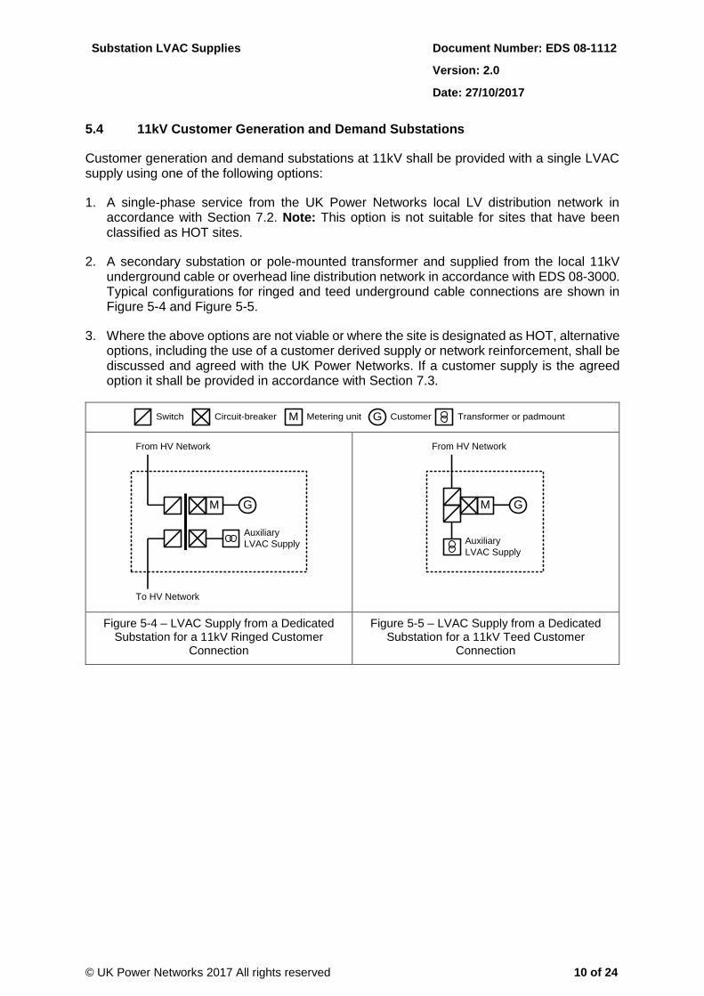
5.4 11kV Customer Generation and Demand Substations
Customer generation and demand substations at 11kV shall be provided with a single LVAC supply using one of the following options:
1. A single-phase service from the UK Power Networks local LV distribution network in accordance with Section 7.2. Note: This option is not suitable for sites that have been classified as HOT sites.
2. A secondary substation or pole-mounted transformer and supplied from the local 11kV underground cable or overhead line distribution network in accordance with EDS 08-3000. Typical configurations for ringed and teed underground cable connections are shown in Figure 5-4 and Figure 5-5.
3. Where the above options are not viable or where the site is designated as HOT, alternative options, including the use of a customer derived supply or network reinforcement, shall be discussed and agreed with the UK Power Networks. If a customer supply is the agreed option it shall be provided in accordance with Section 7.3.
Switch M GCircuit-breaker Transformer or padmountMetering unit Customer
Auxiliary
LVAC Supply
M G
From HV Network
To HV Network
M
Auxiliary
LVAC Supply
G
From HV Network
Figure 5-4 – LVAC Supply from a Dedicated Substation for a 11kV Ringed Customer
Connection
Figure 5-5 – LVAC Supply from a Dedicated Substation for a 11kV Teed Customer
Connection

Substation LVAC Supplies Document Number: EDS 08-1112
Version: 2.0
Date: 27/10/2017
© UK Power Networks 2017 All rights reserved 11 of 24
6 Network Substations
6.1 Overview
The provision of LVAC supplies to UK Power Networks substations has developed differently across the three licence areas. An overview of existing legacy arrangements is given in Appendix C.
The following sections provide a harmonised solution across all three areas while maintaining the status quo at existing substations where the assets continue to remain in a healthy condition. However if changes are required the options detailed in this document shall be applied.
6.2 National Grid Sites
LV supplies to National Grid sites shall be provided in accordance with EDS 08-2108.
6.3 HOT Sites
LV supplies to HOT grid and primary substations shall be provided in accordance with EDS 08-2108.
LV supplies to HOT secondary sites shall be provided in accordance with EDS 06-0014 and ECS 06-0023.
6.4 Grid Substations
For the purposes of this standard, a grid substation is classified as a substation where the highest voltage is 132kV or 66kV. Refer to Section 6.3 for LV supplies to HOT sites.
Grid substations shall be provided with a dual (main and backup) LVAC supply as detailed in Sections 6.4.1 or 6.4.3. Both the main and backup supply shall be capable of supporting the full load. Appendix B includes a load calculation example.
The LVAC supply shall be provided to an indoor LVAC switchboard. At large grid sites with distributed buildings the use of multiple LVAC switchboards may considered where beneficial. The switchboard shall include a three-phase generator connection and a manual changeover switch to prevent paralleling with normal LVAC supplies. Refer to Appendix A for changeover functionality. Note: Outdoor LVAC boards shall not be used.
6.4.1 Multiple Transformer Substations
At a grid substation with multiple transformers the main and backup LVAC supply shall be derived from different auxiliary or earthing/auxiliary transformers such that the loss of a single circuit or upstream substation shall not affect the LVAC supply. The auxiliary transformers shall be connected to either:
Independent circuits (Figure 6-1).
Independent banked transformers (Figure 6-2).
One winding of a three-winding transformer (Figure 6-3).
At grid substations that require n-2 resilience a main and two backup LVAC supplies shall be provided utilising three different auxiliary or earthing/auxiliary transformers.

Substation LVAC Supplies Document Number: EDS 08-1112
Version: 2.0
Date: 27/10/2017
© UK Power Networks 2017 All rights reserved 12 of 24
Note:
At grid substations with more than two grid transformers only two transformers shall be used for LVAC supplies.
At grid substations with water-cooled transformers every transformer shall have an auxiliary transformer due to the zero rating during the loss of cooling and the potential for forced tripping in these circumstances.
At grid substations with multiple voltage transformers refer to Section 6.4.2
Grid Substation Under Design
Remote Substation A Remote Substation B
LVAC
Supply 1
LVAC
Supply 2
Figure 6-1 – Grid Substation LVAC Supply from Independent Transformers
Grid Substation Under Design
Incomer 1
LVAC
Supply 1
LVAC
Supply 2
Incomer 3Incomer 2
Figure 6-2 – Grid Substation LVAC Supply from Banked Transformers
Grid Substation Under Design
Incomer 1
LVAC
Supply 1
Incomer 1
LVAC
Supply 2
Figure 6-3 – Grid Substation LVAC Supply from a Three-winding Transformer

Substation LVAC Supplies Document Number: EDS 08-1112
Version: 2.0
Date: 27/10/2017
© UK Power Networks 2017 All rights reserved 13 of 24
6.4.2 Grid Substations with Multiple Voltages
At a substation with multiple voltages (e.g. 132/33kV and 33/11kV) the HV winding of the transformer with the highest voltage (e.g. 132kV) shall be equipped with the auxiliary transformer (Figure 6-4). If there are existing auxiliary transformers at lower voltages then these may be used for LVAC supplies provided they are of a sufficient size to meet the required demand (Figure 6-5). However where there is interconnector at an intermediate voltage e.g. 33kV either option may be used to ensure the LVAC supply has the highest possible level of resilience.
Grid Substation Under Design
Remote 132kV Substation
LVAC
Supply 1
LVAC
Supply 2
33kV
11kV
Grid Substation Under Design
Remote 132kV Substation
33kV
11kV
LVAC
Supply 1
LVAC
Supply 2
Figure 6-4 – Grid Substation with Multiple Voltage Levels – LVAC Supply New Option
Figure 6-5 – Grid Substation with Multiple Voltage Levels – LVAC Supply Existing Option
6.4.3 Single Transformer Substations
At a grid substation with a single transformer:
The main LVAC supply shall be derived from an auxiliary or earthing/auxiliary transformer.
The backup LVAC supply shall be derived from a secondary substation and supplied from the local 11kV underground cable or overhead line. Where possible the backup shall remain energised for the loss of the transformer.

Substation LVAC Supplies Document Number: EDS 08-1112
Version: 2.0
Date: 27/10/2017
© UK Power Networks 2017 All rights reserved 14 of 24
6.5 Primary Substations
For the purposes of this standard, a primary substation is classified as a substation where the highest voltage is 33kV. Refer to Section 6.3 for LV supplies to HOT sites.
Primary substations shall be provided with a single LVAC supply using one of the following options:
1. A dedicated secondary substation provided in accordance with EDS 08-3000, located within the boundary of the primary substation.
2. In rural locations, a pole-mounted transformer in accordance with EDS 08-3000 may be used.
The LVAC supply shall be provided to an indoor LVAC switchboard. The switchboard shall include a three-phase generator connection and a manual changeover switch to prevent paralleling with normal LVAC supplies. Refer to Appendix A for changeover functionality.
6.6 Secondary Substations
For the purposes of this standard, a secondary substation is classified as a substation where the highest voltage is below 33kV (e.g. 20kV, 11kV or 6.6kV). Refer to Section 6.3 for LV supplies to HOT sites.
6.6.1 GRP or Brick-built Secondary Substations
GRP or brick-built secondary substations shall be provided with an LVAC supply using one of the following options:
1. A 32A auxiliary supply directly from the LV cabinet/board using a minimum 2.5mm2 SWA cable (refer to EAS 02-0000) and terminated in a 100A cut-out (refer to EAS 13-0000) fused at 30A.
2. A single-phase service from an LV cabinet/board/pillar or LV network within the substation in accordance with Section 7.2.
3. A single-phase service from the UK Power Networks local LV distribution network in accordance with Section 7.2.

Substation LVAC Supplies Document Number: EDS 08-1112
Version: 2.0
Date: 27/10/2017
© UK Power Networks 2017 All rights reserved 15 of 24
6.6.2 Outdoor Secondary Substations
Outdoor secondary substations (e.g. close-boarded or metal fence) shall be provided with an LVAC supply where required to power an RTU using one of the following options:
1. A 32A auxiliary supply directly from the LV cabinet using a minimum 2.5mm2 SWA cable (refer to EAS 02-0000) and terminated in the RTU equipment.
2. A 100A single-phase supply from the LV pillar (within the substation) as follows:
The supply shall be derived either directly from existing spare auxiliary terminals (fused at 5A or less) or via an un-switched fused connection unit (refer to EDS 07-1119) fused at 3A and mounted securely in the pillar.
The supply shall be connected to the RTU equipment using a minimum 2.5mm2 SWA cable (refer to EAS 02-0000). To avoid a parallel earth path the armouring shall only be earthed at the RTU end with a suitable gland, the LV pillar end should be secured in a plastic gland. Any unused cores should be made safe and left as spare.
The supply shall be labelled 'CAUTION – Automation Supply' using a suitable label.
The un-switched fused connection unit shall be connected to the RTU equipment using a minimum 2.5mm2 SWA cable (refer to EAS 02-0000). Any unused cores shall be made safe and left as spare.
Note: The provision of an LV supply from an existing pillar requires careful consideration and any proposed method of working shall be covered by a site specific risk assessment.
3. A 100A single-phase service from the UK Power Networks local LV distribution network as follows:
The service shall be via a 25mm2 single-phase aluminium cable (refer to EAS 02-0000) and be no greater than 40 metres in length.
The cable shall be installed in a 32mm internal diameter duct (refer to EAS 02-0000) and terminated in a 25A cut-out (refer to EAS 13-0000) fused at 16A.
The cut-out shall be mounted in a LV mini pillar (refer to EAS 13-0000) with an un-switched fused connection unit (refer to EDS 07-1119).
The fused connection unit shall be connected to the RTU equipment using a minimum 2.5mm2 SWA cable (refer to EAS 02-0000). To avoid a parallel earth path the armouring shall only be earthed at the RTU end with a suitable gland, the LV mini pillar end should be secured in a plastic gland. Any unused cores should be made safe and left as spare.
The supply shall be labelled 'CAUTION – Automation Supply' using a suitable label.
A standard 'Danger' notice shall be attached to the pillar.
An earth terminal shall not be provided from the incoming service (i.e. TT earthing system); all earthing and bonding shall use the substation earthing system in accordance with the UK Power Networks earthing standards.

Substation LVAC Supplies Document Number: EDS 08-1112
Version: 2.0
Date: 27/10/2017
© UK Power Networks 2017 All rights reserved 16 of 24
6.7 Switching Stations
For the purposes of this standard, a switching station is a substation where there is no local transformation on site. Refer to Section 6.3 for LVAC supplies to HOT sites.
6.7.1 132kV Switching Stations
132kV switching stations shall be provided with a dual (main and backup) LVAC supply from the local network using one of the following options, listed in order of security, subject to availability and practicality:
1. Two secondary substations and supplied from two different circuits (single point of failure is the loss of the primary substation).
2. Two secondary substations and supplied from same circuit but connected to different sections so they can be independently energised (single point of failure is the loss of entire 11kV feeder).
3. Two secondary substations and supplied from the same section of circuit (affected by same fault isolation) that can be back-fed at LV (LVAC supply not affected by loss of a secondary substation or 11kV circuit section).
4. One secondary substation that can be back-fed from the LV network (single point of failure is the loss of the secondary substation).
The highest possible level of security shall be sought at every opportunity.
The LVAC supply shall be provided to an indoor LVAC switchboard. The switchboard shall include a three-phase generator connection and a manual changeover switch to prevent paralleling with normal LVAC supplies. Refer to Appendix A for changeover functionality.
6.7.2 33kV Switching Stations
33kV switching stations shall be provided with a single LVAC supply using one of the following options:
1. A dedicated secondary substation located within the boundary of the switching substation.
2. In rural locations, a pole-mounted transformer in accordance with EDS 08-3000 may be used.
The LVAC supply shall be provided to an indoor LVAC switchboard. The switchboard shall include a three-phase generator connection and a manual changeover switch to prevent paralleling with normal LVAC supplies. Refer to Appendix A for changeover functionality.
6.7.3 Other Switching Stations
Other switching stations shall be provided with a single LVAC supply from the local network using any of the options from Section 6.6. Alternatively, where no LV supply is readily available, a padmount substation shall be installed and supplied from the local 11kV distribution network in accordance with EDS 08-3000.

Substation LVAC Supplies Document Number: EDS 08-1112
Version: 2.0
Date: 27/10/2017
© UK Power Networks 2017 All rights reserved 17 of 24
7 General Requirements
7.1 Secondary Substation
Where specified a secondary substation (including padmount substations) shall be selected and provided in accordance EDS 07-3101 and EDS 07-3102.
The use of padmount substations is acceptable in urban areas where a point of isolation is provided.
7.2 LV Distribution Network or Secondary Substation Supply
Where specified in this document supplies from the LV distribution network or a secondary substation shall be provided as follows:
The service shall be via a 35mm2 single-phase or three-phase aluminium cable (refer to EAS 02-0000).
The cable shall be installed in a 32mm internal diameter duct (refer to EAS 02-0000) and terminated in a 100A single-phase cut-out (refer to EAS 13-0000) fused at 30A 100A three-phase cut-out (refer to EAS 13-0000) fused at 100A.
The cut-out shall be mounted on the substation within 3 metres of the distribution board and be connected to it using 25mm2 tails.
An earth terminal shall not be provided from the incoming service (i.e. TT earthing system); all earthing and bonding shall use the substation earthing system in accordance with the UK Power Networks earthing standards.
7.3 Customer LVAC Supply
Where specified in this document and agreed with UK Power Networks a customer LVAC supply shall be provided from the customer substation as follows:
Be derived from the customer’s essential services board that has the facility for a backup generator (either fixed or mobile).
Include backup via a standby or emergency generator which is provided by the customer and available within 8 hours of the loss of the supply.
Include an external generator connection and changeover switch in the UK Power Networks substation that is accessible to both UK Power Networks and the customer to facilitate generator connections.
Not be affected by any loss of generation infeed through tripping of generator circuit breaker(s).
Be monitored via UK Power Networks SCADA system via the local RTU. An alarm may also be provided to the customer’s SCADA where required.
7.4 Auto-changeover Scheme
An auto-changeover scheme with shall be provided where multiple LVAC supply options are provided to a site. In addition, where a connection for a backup generator is provided a manual changeover/interlocking scheme shall be provided.
The changeover scheme shall be designed to provide the functionality detailed in Appendix A.

Substation LVAC Supplies Document Number: EDS 08-1112
Version: 2.0
Date: 27/10/2017
© UK Power Networks 2017 All rights reserved 18 of 24
7.5 Earthing
The combination of the earthing systems associated with LVAC supplies and HV substations requires careful consideration to ensure dangerous potentials are not transferred between the systems. However, where conditions are suitable, the earthing systems shall be bonded in accordance with the UK Power Networks earthing standards.
Furthermore, LVAC auxiliary supplies derived from the 11(6.6)kV secondary distribution network shall satisfy the earthing requirements detailed in EDS 06-0014 for the supplies to higher voltage sites and supplies to HOT sites.
EDS 06-0019 contains further guidance on the earthing of LVAC supplies associated with customer demand and generator metered connections.
LVAC supplies shall not be provided directly from the LV distribution network to 132kV, 33kV or HOT 11kV sites due to the danger of possible transferred potentials to the LV system and onwards to other UK Power Networks’ customers.
7.6 Substation Electrical Services
Refer to EDS 07-1119 and the relevant substation civil design drawings for further information on substation electrical services.

Substation LVAC Supplies Document Number: EDS 08-1112
Version: 2.0
Date: 27/10/2017
© UK Power Networks 2017 All rights reserved 19 of 24
8 References
8.1 UK Power Networks Standards
EAS 02-0000 Cables and Joints
EAS 13-0000 LV Plant and Equipment
EDS 06-0014 Secondary Substation Earthing Design
EDS 06-0019 Customer EHV and HV Connections (including Generation) Earthing Design and Construction Guidelines
ECS 06-0023 Secondary Distribution Network Earthing Construction
EDS 07-1119 Substation Electrical Services
EDS 07-3101 Pre-design Requirements for Secondary Substations
EDS 07-3102 Secondary Substation Civil Design Standards
EDS 08-0149 Customer Supply Interface
EDS 08-2108 Supplies to HOT Sites and National Grid Sites
EDS 08-3000 HV Network Design
9 Dependant Documents
The documents below are dependent on the content of this document and may be affected by the changes.
EDS 06-0019 Customer EHV and HV Connections (including Generation) Earthing Design and Construction Guidelines
EDS 07-1119 Substation Electrical Services
EDS 08-0149 Customer Supply Interface
EDS 08-3000 HV Network Design
EDS 08-3100 HV Customer Supplies

Substation LVAC Supplies Document Number: EDS 08-1112
Version: 2.0
Date: 27/10/2017
© UK Power Networks 2017 All rights reserved 20 of 24
Appendix A – LVAC Supply Changeover Scheme
LVAC SUPPLY CHOICE
SET SUPPLY TO S1(AUTO CHANGEOVER)
S1 ≥ 85%
S2 ≥ 85%SET SUPPLY TO S2(AUTO CHANGEOVER)
SEND GENERATOR TO SITE
SET SUPPLY TO GENERATOR
(MANUAL CHANGEOVER)
SUPPLIES RESTORED?
S1 OR S2 ≥ 85%
NO
NO
NO
YES
YES
YES
RELEASE MANUAL INTERLOCK TO GENERATOR
Figure A-1 – LVAC Supply Changeover Scheme Flowchart

Substation LVAC Supplies Document Number: EDS 08-1112
Version: 2.0
Date: 27/10/2017
© UK Power Networks 2017 All rights reserved 21 of 24
XO
R
XO
R
AN
D
OR AN
D
OR
NOT
NOT
Ma
in S
up
ply
Ba
cku
p S
up
ply
Ge
ne
rato
r
Auto-Changeover with
Interlocking
Manual Changeover with
Interlocking for Generator
AND: all inputs true gives a true output
NOT: false input gives a true output
OR: any input true gives a true output
XOR: only one input true gives a true output
Figure A-2 – LVAC Supply Changeover Scheme Logic
Substation LVAC Supplies Document Number: EDS 08-1112
Version: 2.0
Date: 27/10/2017
© UK Power Networks 2017 All rights reserved 22 of 24
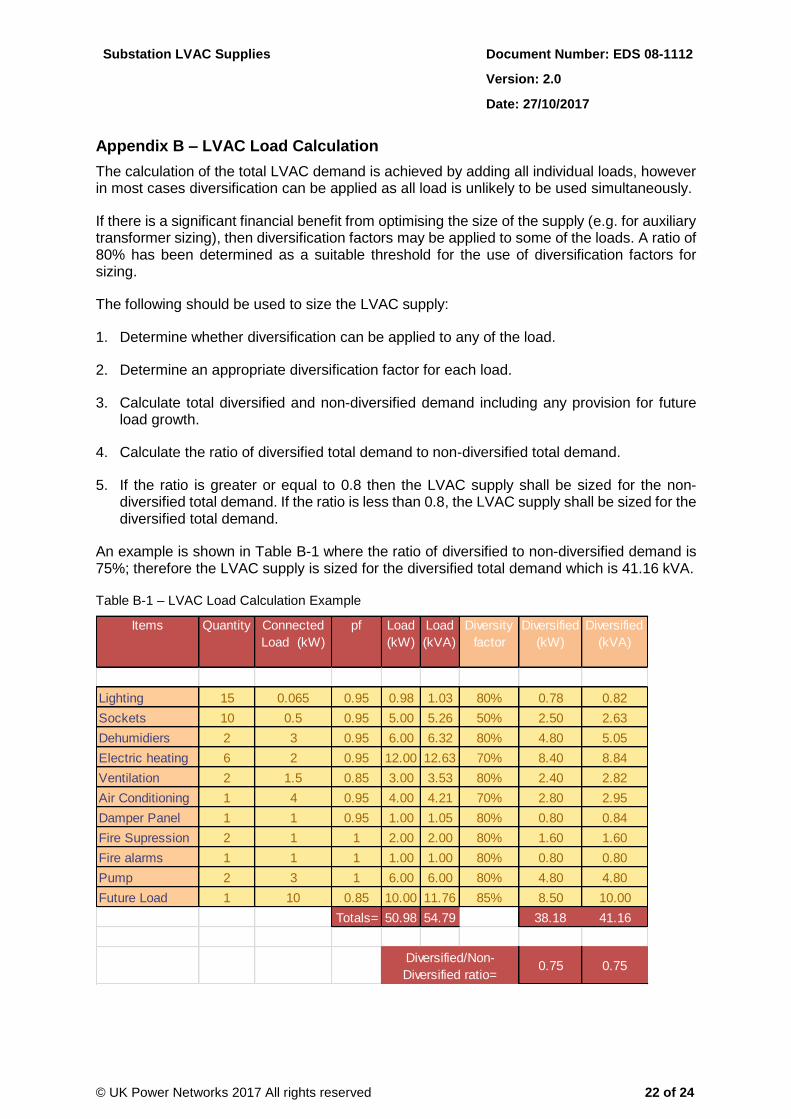
Appendix B – LVAC Load Calculation
The calculation of the total LVAC demand is achieved by adding all individual loads, however in most cases diversification can be applied as all load is unlikely to be used simultaneously.
If there is a significant financial benefit from optimising the size of the supply (e.g. for auxiliary transformer sizing), then diversification factors may be applied to some of the loads. A ratio of 80% has been determined as a suitable threshold for the use of diversification factors for sizing.
The following should be used to size the LVAC supply:
1. Determine whether diversification can be applied to any of the load.
2. Determine an appropriate diversification factor for each load.
3. Calculate total diversified and non-diversified demand including any provision for future load growth.
4. Calculate the ratio of diversified total demand to non-diversified total demand.
5. If the ratio is greater or equal to 0.8 then the LVAC supply shall be sized for the non-diversified total demand. If the ratio is less than 0.8, the LVAC supply shall be sized for the diversified total demand.
An example is shown in Table B-1 where the ratio of diversified to non-diversified demand is 75%; therefore the LVAC supply is sized for the diversified total demand which is 41.16 kVA.
Table B-1 – LVAC Load Calculation Example
Items Quantity Connected
Load (kW)
pf Load
(kW)
Load
(kVA)
Diversity
factor
Diversified
(kW)
Diversified
(kVA)
Lighting 15 0.065 0.95 0.98 1.03 80% 0.78 0.82
Sockets 10 0.5 0.95 5.00 5.26 50% 2.50 2.63
Dehumidiers 2 3 0.95 6.00 6.32 80% 4.80 5.05
Electric heating 6 2 0.95 12.00 12.63 70% 8.40 8.84
Ventilation 2 1.5 0.85 3.00 3.53 80% 2.40 2.82
Air Conditioning 1 4 0.95 4.00 4.21 70% 2.80 2.95
Damper Panel 1 1 0.95 1.00 1.05 80% 0.80 0.84
Fire Supression 2 1 1 2.00 2.00 80% 1.60 1.60
Fire alarms 1 1 1 1.00 1.00 80% 0.80 0.80
Pump 2 3 1 6.00 6.00 80% 4.80 4.80
Future Load 1 10 0.85 10.00 11.76 85% 8.50 10.00
Totals= 50.98 54.79 38.18 41.16
0.75 0.75Diversified/Non-
Diversified ratio=

Substation LVAC Supplies Document Number: EDS 08-1112
Version: 2.0
Date: 27/10/2017
© UK Power Networks 2017 All rights reserved 23 of 24
Appendix C – Legacy Arrangements
C.1 LPN
At existing 132/11kV 60MVA transformer sites each transformer has its own auxiliary transformer (normally 100kVA) and transformer LV board feeding its specific transformer requirements. All transformer LV boards are linked together with auto-changeover between systems and interlocked to prevent paralleling.
The essential services switchboard and building services switchboard have a connection to one of the LV boards (so has an auto-changeover secure supply). There is no distinction between essential and non-essential services in this arrangement.
For older 132/33kV, 66/33kV sites: The arrangement follows the earlier CEGB practice. Typically, each transformer has its own auxiliary transformer and transformer LV board feeding its specific transformer requirements. This is normally an outdoor board. All Transformer LV boards are linked together and interlocked to prevent paralleling. A single LV switchboard (indoor) with backup (maybe auto-changeover or manual) on site feeds essential services and building services. This is fed from one of the Transformer LV boards. The other side for auto-changeover may be from another transformer LV board or from the local LV network’. There is no distinction between essential and non-essential services in this arrangement.
For new 132kV switchgear including 132/11kV 60MVA transformer sites, each transformer has its own auxiliary transformer and transformer LV board feeding its specific transformer requirements. All transformer LV boards are linked together and interlocked to prevent paralleling. A single LV switchboard with auto-changeover on site feeds essential services and building services. This is fed from a secondary substation on site (or larger auxiliary transformer, i.e. 200KVA). The other LV infeed for auto-changeover may be from another secondary substation/large auxiliary transformer/network LV - typically each a secondary on a different section of 11kV switchboard. There is no distinction between essential and non-essential services.
For older 33/11kV, 66/11kV installations (all transformer ONAN type): A single LV switchboard with manual changeover on site feeds essential services and building services. Both sides of changeover fed from LV network (typically each fed from a secondary substation on different section of 11kV switchboard). There is no distinction between essential and non-essential services in this arrangement.
For older 33/11kV, 66/11kV installations (transformer OFAN,OFAF, ONAF - including previous ONAN sites where enhanced cooling been added): A single LV switchboard with auto-changeover on site feeds essential services and building services. Both sides of the auto-changeover scheme are fed from the LV network (typically each fed from a secondary substation on different section of 11kV switchboard). There is no distinction between essential and non-essential services in this arrangement.

Substation LVAC Supplies Document Number: EDS 08-1112
Version: 2.0
Date: 27/10/2017
© UK Power Networks 2017 All rights reserved 24 of 24
C.2 EPN
For earlier designs of grid site (132/33kV), as with early LPN designs, LV supplies are taken from the earthing/ auxiliary transformers on the LV side of the transformer. Each is taken to a dedicated LV board (normally outdoors).
An indoor LV switchboard is normally fed from either one of the outdoor LV boards and a network supply, or both outdoor LV boards.
This approach seems to have been maintained.
For primary sites, early designs had a single LV supply from the network. Later urban substation designs became more complex with either two padmount transformers with an auto-changeover scheme or a single padmount and a network supply. A generator socket is also provided on the single LV board.
For rural primary substations, early designs relied upon a single supply from a local pole transformer. Later designs added in a supply from a second pole transformer on the opposite 11kV busbar section to the first supply.
C.3 SPN
Grid sites are in the main the same as the original CEGB design; that is LV supplies are taken from the earthing/auxiliary transformers and fed into the local LV boards which in turn feed the indoor LV board.
For primary sites, a single LV supply is taken from the network or a local secondary substation within the primary substation boundary.
The latest design of sites has maintained this approach.