EDP300 / TZIDC DATASHEET - BHB · Lateral attachment is in accordance with DIN / IEC 534 (lateral...
56
EDP300 / TZIDC DATASHEET JUNHO 2013
Transcript of EDP300 / TZIDC DATASHEET - BHB · Lateral attachment is in accordance with DIN / IEC 534 (lateral...

EDP300 / TZIDC
DATASHEET
JUNHO 2013
Data Sheet DS/EDP300-EN Rev. B
PositionMaster EDP300 Electro-Pneumatic Positioner
Compact, well-proven, and flexible
High air capacity Diagnostics capability Resistant to overpressure Robust and environmentally ruggedized Easy to commission
Approvals for explosion protection — ATEX — IECEx — FM / CSA — GOST For SIL2 safety loop Extended diagnostics
Change from one to two columns

PositionMaster EDP300 Electro-Pneumatic Positioner
2 DS/EDP300-EN Rev. B | PositionMaster EDP300
Brief description
The PositionMaster EDP300 is an electronically configurable positioner with communication capabilities designed for mounting to pneumatic linear or part-turn actuators. It features a small and compact design, a modular construction, and an excellent cost-performance ratio. Fully automatic determination of the control parameters and adaptation to the final control element yield considerable time savings and an optimal control behavior. Pneumatics An I/P module with subsequent pneumatic amplifier is used to control the pneumatic actuator. The well-proven I/P module proportionally converts the permanent electrical setpoint signal from the CPU into a pneumatic signal used to adjust a 3/3-way valve. The air flow for pressurizing or depressurizing the actuator is continuously adjusted. As a result, excellent control is achieved. When reaching the setpoint, the 3/3-way valve is closed in center position to minimize the air consumption. Four different pneumatics versions are available: for single-acting or double-acting actuators, each with “fail-safe” or “fail-freeze” function.
“Fail-safe” function If the electrical supply power fails, the positioner output 1 is depressurized, and the pneumatic actuator’s return spring moves the valve to the defined safe position. In case of a double-acting actuator the second output 2 is additionally pressurized. “Fail-freeze” function If the electrical supply power fails, the positioner output 1 (and 2, if applicable) is closed and the pneumatic actuator stops (“freezes”) the valve in the current position. If the compressed air supply power fails, the positioner depressurizes the actuator.
Operation The positioner has a built-in LCD-indicator with a multi-line LCD display and 4 pushbuttons for commissioning, configuration, and monitoring during live operation. Alternatively, the appropriate DTM/EDD can be used via the available communication interface. Communication The positioner supports HART5 and HART7 communication. Inputs / Outputs In addition to its input for the analog position setpoint, the positioner is equipped with a digital input which can be used to activate control system functions in the device. A digital output allows you to output collective alarms or fault messages.
Modular design The basic model can be enhanced at any time by retrofitting optional equipment. Option modules for analog and digital feedback, an emergency shutdown module, and pressure sensors for valve diagnostics can be installed. A module for a universal analog input can also be installed to which any device supplying a 4 … 20 mA signal can be connected. Additionally, a mechanical position indicator, proximity switches or 24 V microswitches are available for indicating the position independently of the mother board function. Diagnostics The positioner has three optional pressure sensors which can be used for reliable diagnostics of the valve, the pneumatic drive, and the positioner.
Change from two to one column

PositionMaster EDP300 | DS/EDP300-EN Rev. B 3
Schematic representation Basic device Optional upgrades
M10112
A
B C
2
9
11
12
13
14
15
3
4
5
1
6
7
8
10
Fig. 1: Schematic diagram of the positioner
A Electronic | B Pneumatic | C Position sensor | 1 4 ... 20 mA / bus connection | 2 Digital input | 3 Alarm output | 4 Supply air | 5 Output 1 | 6 Output 2 | 7 Analog feedback | 8 Binary feedback | 9 Shutdown module | 10 Universal input | 11 Pressure sensor | 12 Mechanical end position switch 24 V microswitch | 13 Proximity switches (NC) | 14 Proximity switches (NO) | 15 Optical position indicator kllkl
IMPORTANT (NOTE) With optional upgrades either the “mechanical feedback with proximity switches” (13 or 14) or the “mechanical feedback with microswitch 24 V” (12) can be used. Only two different plug-in modules can ever be used.
PositionMaster EDP300 Electro-Pneumatic Positioner
4 DS/EDP300-EN Rev. B | PositionMaster EDP300
Change from one to two columns
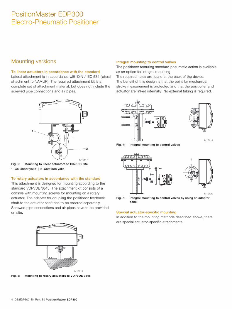
Mounting versions
To linear actuators in accordance with the standard Lateral attachment is in accordance with DIN / IEC 534 (lateral attachment to NAMUR). The required attachment kit is a complete set of attachment material, but does not include the screwed pipe connections and air pipes.
M10117
1
2
Fig. 2: Mounting to linear actuators to DIN/IEC 534
1 Columnar yoke | 2 Cast iron yoke
To rotary actuators in accordance with the standard This attachment is designed for mounting according to the standard VDI/VDE 3845. The attachment kit consists of a console with mounting screws for mounting on a rotary actuator. The adapter for coupling the positioner feedback shaft to the actuator shaft has to be ordered separately. Screwed pipe connections and air pipes have to be provided on site.
M10119 Fig. 3: Mounting to rotary actuators to VDI/VDE 3845
Integral mounting to control valves The positioner featuring standard pneumatic action is available as an option for integral mounting. The required holes are found at the back of the device. The benefit of this design is that the point for mechanical stroke measurement is protected and that the positioner and actuator are linked internally. No external tubing is required.
M10118 Fig. 4: Integral mounting to control valves
M10120 Fig. 5: Integral mounting to control valves by using an adapter
panel
Special actuator-specific mounting In addition to the mounting methods described above, there are special actuator-specific attachments.
Change from two to one column

PositionMaster EDP300 | DS/EDP300-EN Rev. B 5
Change from one to two columns
Device parameters
General remarks Microprocessor-based position control in the positioner optimizes control. The positioner features high-precision control functions and high operational reliability. Due to their elaborate structure and easy accessibility, the device parameters can be quickly adapted to the respective application. The total range of parameters includes: — Operating parameters — Adjustment parameters — Monitoring parameters — Diagnostics parameters — Maintenance parameters Operating parameters The following operating parameters can be set manually if required: Setpoint signal 0 ... 100 % freely selectable for split-range operation For 4 ... 20 mA and HART version: — Signal min. 4 mA, max. signal 20 mA (0 ... 100 %) — Min. range 20 % (3.2 mA) — Recommended range > 50 % (8.0 mA) Action (setpoint signal) Increasing: Position value 0 ... 100 % = direction 0 ... 100 % Decreasing: Setpoint signal 100 ... 0 % = direction 0 ... 100 % Characteristic curve (travel = f {setpoint signal}) Linear, equal percentage 1:25 or 1:50 or 25:1 or 50:1 or freely configurable with 20 reference points. Travel limit The positioning travel, i.e. the stroke or angle of rotation, can be reduced as required within the full range of 0 ... 100 %, provided that a minimum value of 20% is observed.
Shut-off function This parameter can be set separately for each end position. When the respective configured limit value is exceeded, the shut-off function causes immediate travel of the actuator until reaching the set end position. When the shut-off value is set to “0”, the position is further controlled, even in the respective end position. Travel time prolongation This function can be used to increase the max. travel time for full travel. This time parameter can be set separately for each direction. Switching points for the position
You can use these parameters to define two position limits for signaling (see option “Module for digital position feedback”). Alarm output The alarms generated in the positioner can be polled via the digital output as a collective alarm. The desired information can be selected via the LCD display or remotely via the configuration program. The output can be set to “active high” or “active low”, as required. Digital input For the digital input, one of the following safety options can be selected. You may use the LCD display or configuration program to select an option. — No function (default) — Move to position substitute value (freely selectable) — Start "Partial Stroke Test" — Ventilate output 1, evacuate output 2 — Ventilate output 2, evacuate output 1 — Service required — Move to 0 % position — Move to 100 % position — Hold previous position — Disable local configuration — Disable local configuration and operation — Disable all access (no local or remote access via a PC) The selected function is activated once the 24 V DC signal is no longer applied (< 11 V DC).
PositionMaster EDP300 Electro-Pneumatic Positioner
6 DS/EDP300-EN Rev. B | PositionMaster EDP300
Adjustment parameters The positioner has a special function for automatic adjustment of the parameters. Additionally, the control parameters can be set automatically (in adaptive control mode) or manually to optimally adapt them to the process requirements. Zone Upon reaching this value, the position is readjusted more slowly until the dead band is reached. Dead band (sensitivity) When reaching the dead band, the position is held. Display 0 ... 100 % Adjusting the display (0 ... 100 %) according to the direction of action for opening or closing the actuator.
Diagnostics Various functions for permanent operational monitoring are implemented in the PositionMaster EDP300 operating program. The following states will be detected and indicated, e. g.: — Setpoint signal out of range 0 ... 100 % or 4 ... 20 mA — Position out of the adjusted range — Positioning time-out (adjustable time parameter) — Position controller inactive — Counter limit values exceeded (can be set via DTM/EDD)
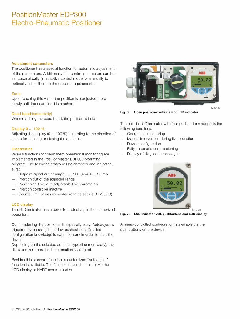
LCD display The LCD indicator has a cover to protect against unauthorized operation. Commissioning the positioner is especially easy. Autoadjust is triggered by pressing just a few pushbuttons. Detailed configuration knowledge is not necessary in order to start the device. Depending on the selected actuator type (linear or rotary), the displayed zero position is automatically adapted. Besides this standard function, a customized “Autoadjust” function is available. The function is launched either via the LCD display or HART communication.
M10125 Fig. 6: Open positioner with view of LCD indicator
The built-in LCD indicator with four pushbuttons supports the following functions: — Operational monitoring — Manual intervention during live operation — Device configuration — Fully automatic commissioning — Display of diagnostic messages
M10126 Fig. 7: LCD indicator with pushbuttons and LCD display
A menu-controlled configuration is available via the pushbuttons on the device.

PositionMaster EDP300 | DS/EDP300-EN Rev. B 7
The multi-line LCD indicator is permanently updated and adapted during operation to provide the user with optional information as relevant. During control operation (control with or without adaptation) the following data can be called up by pressing the pushbuttons briefly: — Position Pos [%] — Position Pos [°] — Setpoint SP [%] — Setpoint SP [mA] — Control deviation DEV [%] — Electronics temperature [°C, °F, °R, K] — Supply pressure PIN [unit] — Pressure output 1 PY1 [unit] — Pressure output 2 PY2 [unit] — Differential pressure DP [unit] — Universal input value UIN [unit]
— Malfunctions, alarms, messages The possible reason is also displayed, along with the recommended remedial action. In the event of an error, a message consisting of an icon and text (e.g., electronics) appears at the bottom of the process display. The text displayed provides information about the area in which the error has occurred. The error messages are divided into four groups in accordance with the NAMUR classification scheme:
Symbol Description
Error / Failure
Functional check
Out of specification
Maintenance required
(The group assignment can only be changed using a DTM or EDD.)
Additionally, the error messages are divided into the following areas: Area Description
Actuator Diagnostics messages affecting the valve or the
pneumatic actuator
Operation Diagnostics messages affecting the operation of
the positioner
Process Diagnostics messages relating to the process and
displaying problems or states
Sensor Alarms informing of problems affecting the reading
of the valve position
Electronic Displays errors in the device electronics
Configuration Detects if the positioner configuration is missing or
faulty
Histograms recording — Positioning time-outs — Valve movements — Valve strokes — Most used valve position — Universal input Access to extended monitoring parameters is possible via HART communication, the DTM, and the EDD.
The diagnostics parameters in the operating program provide information about the operating conditions of the actuator. For example: — Dead band time limit — Leakage detection — Temperature monitoring — Stiction detection — Sliding friction detection — Hysteresis — Valve seat wear From this information the operator can derive what maintenance work is required, and when.
?
PositionMaster EDP300 Electro-Pneumatic Positioner
8 DS/EDP300-EN Rev. B | PositionMaster EDP300
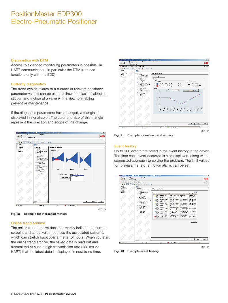
Diagnostics with DTM Access to extended monitoring parameters is possible via HART communication, in particular the DTM (reduced functions only with the EDD). Butterfly diagnostics The trend (which relates to a number of relevant positioner parameter values) can be used to draw conclusions about the stiction and friction of a valve with a view to enabling preventive maintenance. If the diagnostic parameters have changed, a triangle is displayed in signal color. The color and size of this triangle represent the direction and scope of the change.
M10114 Fig. 8: Example for increased friction
Online trend archive The online trend archive does not merely indicate the current setpoint and actual value, but also the associated patterns, which can stretch back over a matter of hours. When you start the online trend archive, the saved data is read out and transmitted at such a high transmission rate (100 ms via HART) that the latest data is displayed in next to no time.
M10115 Fig. 9: Example for online trend archive
Event history Up to 100 events are saved in the event history in the device. The time each event occurred is also displayed, along with a suggested approach to solving the problem. The limit values for (pre-)alarms, e.g. a friction alarm, can be set.
M10116 Fig. 10: Example event history
PositionMaster EDP300 | DS/EDP300-EN Rev. B 9
Valve signature (only with pressure option) When the valve signature starts, the entire valve operating range is covered for the "open and closed directions". High-resolution plots are generated for the pressure patterns at the diagnostic pressure sensors. In addition, the signal waveform for the universal input is recorded. Once the signature has expired, the parameters selected by the user are loaded from the device and displayed. Depending on the quantity of data selected, it may take several minutes to transfer all the parameter values. Up to 5 valve signatures can be saved in the device; these can be compared so that valve diagnostics can be performed for the purpose of preventive maintenance.
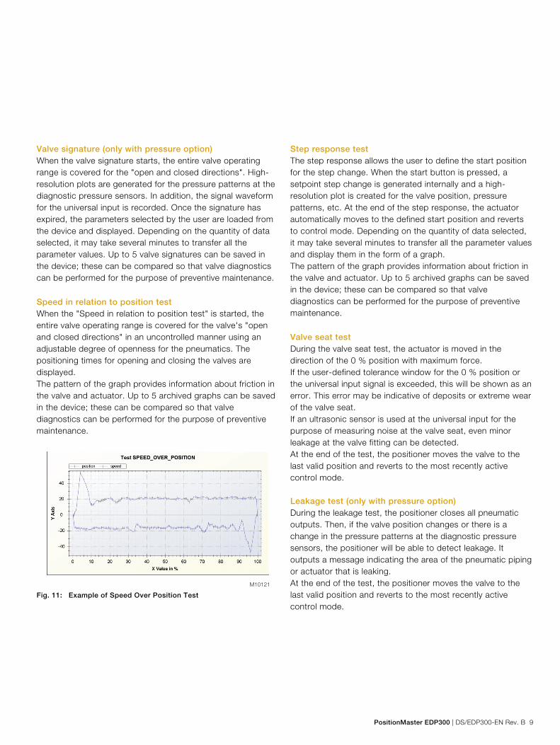
Speed in relation to position test When the "Speed in relation to position test" is started, the entire valve operating range is covered for the valve's "open and closed directions" in an uncontrolled manner using an adjustable degree of openness for the pneumatics. The positioning times for opening and closing the valves are displayed. The pattern of the graph provides information about friction in the valve and actuator. Up to 5 archived graphs can be saved in the device; these can be compared so that valve diagnostics can be performed for the purpose of preventive maintenance.
Fig. 11: Example of Speed Over Position Test
Step response test The step response allows the user to define the start position for the step change. When the start button is pressed, a setpoint step change is generated internally and a high-resolution plot is created for the valve position, pressure patterns, etc. At the end of the step response, the actuator automatically moves to the defined start position and reverts to control mode. Depending on the quantity of data selected, it may take several minutes to transfer all the parameter values and display them in the form of a graph. The pattern of the graph provides information about friction in the valve and actuator. Up to 5 archived graphs can be saved in the device; these can be compared so that valve diagnostics can be performed for the purpose of preventive maintenance.
Valve seat test During the valve seat test, the actuator is moved in the direction of the 0 % position with maximum force. If the user-defined tolerance window for the 0 % position or the universal input signal is exceeded, this will be shown as an error. This error may be indicative of deposits or extreme wear of the valve seat. If an ultrasonic sensor is used at the universal input for the purpose of measuring noise at the valve seat, even minor leakage at the valve fitting can be detected. At the end of the test, the positioner moves the valve to the last valid position and reverts to the most recently active control mode. Leakage test (only with pressure option) During the leakage test, the positioner closes all pneumatic outputs. Then, if the valve position changes or there is a change in the pressure patterns at the diagnostic pressure sensors, the positioner will be able to detect leakage. It outputs a message indicating the area of the pneumatic piping or actuator that is leaking. At the end of the test, the positioner moves the valve to the last valid position and reverts to the most recently active control mode.
M10121
PositionMaster EDP300 Electro-Pneumatic Positioner
10 DS/EDP300-EN Rev. B | PositionMaster EDP300
Partial Stroke Test The Partial Stroke Test is used to check the function of the safe position of ESD (emergency shutdown) valves. The test can be started both locally on the device, time-controlled or using the DTM. The positioner evacuates output 1 until the position change defined in advance occurs. If this does not happen within the set time, an alarm can be output. This helps prevent unexpected failures of the valve. At the end of the test, the positioner moves the valve to the last valid position and reverts to the most recently active control mode. There are two separate parameters available for reducing the speed at which the valve moves in the corresponding direction.
Drag indicator This diagram shows the minimum, maximum, and average values for a selectable parameter in 3 different intervals, which are offset in relation to one another. The drag indicator trend, which is plotted against time, makes it possible to plan preventive action so that a failure in terms of the valves and fittings can be avoided.
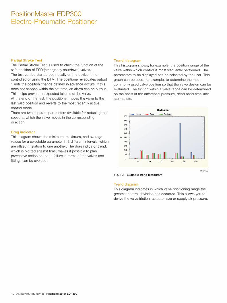
Trend histogram This histogram shows, for example, the position range of the valve within which control is most frequently performed. The parameters to be displayed can be selected by the user. This graph can be used, for example, to determine the most commonly used valve position so that the valve design can be evaluated. The friction within a valve range can be determined on the basis of the differential pressure, dead band time limit alarms, etc.
M10122 Fig. 12: Example trend histogram
Trend diagram This diagram indicates in which valve positioning range the greatest control deviation has occurred. This allows you to derive the valve friction, actuator size or supply air pressure.

PositionMaster EDP300 | DS/EDP300-EN Rev. B 11
Friction detection test (only with pressure option) Once the function is initiated, a high-resolution plot of the differential pressure and universal input signal is generated for the valve's entire operating range. At the end of the test, the positioner moves the valve to the last valid position and reverts to the most recently active control mode. Limit values for the dynamic friction, stiction and universal input signal can be defined, using 11 reference points in each case. If the corresponding alarms are also activated in "Diagnostics -> Configure diagnostics", alarms can be output during operation as soon as the defined limit values are overshot. Further diagnostic parameters are possible with the optional pressure sensors. They include: — Supply air pressure too low — Supply air pressure too high — Pressure shocks in the supply air — Valve signature — Leakage localization Additionally, limit values can be defined for these parameters. When they are exceeded, an alarm is reported. The following values are e.g. determined: — Number of movements performed by the actuator — Total travel
Test cycles Characteristic curves mapping a setpoint cyclically and internally are stored in the device. The DTM can be used to track the position of the actuator. This provides a means of checking the dynamic response of the entire actuator, for example, and determining the limit frequency automatically.
M10127 Fig. 13: Example test cycles

PositionMaster EDP300 Electro-Pneumatic Positioner
12 DS/EDP300-EN Rev. B | PositionMaster EDP300
Communication
DTM The DTM (Device Type Manager) for the positioner PositionMaster EDP300 is based on FDT/DTM technology (FDT 1.2/1.2.1) and can be either integrated into a control system or loaded on a PC with DAT200 Asset Vision Basic. This allows you to work with the same user interface in the commissioning phase, during operation, and for service tasks involving monitoring the device, setting parameters, and reading out data. Communication is based on the HART protocol. Reading data out from the device has no effect on active operation. Newly set parameters are saved in the non-volatile memory directly upon download to the device, and become active immediately.
EDD The EDD (Electronic Device Description) is used to read and modify simple device parameters on handheld terminals or in the vicinity of the system.
Change from two to one column

PositionMaster EDP300 | DS/EDP300-EN Rev. B 13
Dimensions
Mounting drawings All dimensions in mm (inch)
M10529
14
,5(0
.57
)
1(0
.04
)
Ø 8 (0.31) h9
Fig. 14: Top view
M10528
40 (1.57)
120 (4.72)
97
(3.8
2)
Fig. 15: EDP300 positioner with pressure gauge block and filter regulator mounted

PositionMaster EDP300 Electro-Pneumatic Positioner
14 DS/EDP300-EN Rev. B | PositionMaster EDP300
M10524
104,5 (4.11)
60 (2.36)
33,5 (1.32)
23 (0.91)
58 (2.28)
50(1.97)
45°
25
(0.9
8)
2(0
.08
)
7(0
.28
)
65
(2.5
6)
50
(1.9
7)
10
4(4
.09
)
206 (8.11)
Fig. 16: Front and rear views
PositionMaster EDP300 | DS/EDP300-EN Rev. B 15
M10530
14,5
(0.57)
1,8
(0.07)115,5
44
(1.73)
28
(1.1
0)
10
(0.39)
M5
28
(1.1
0)
14
(0.5
5)
28,5
(1.1
2)
2
(0.0
7)
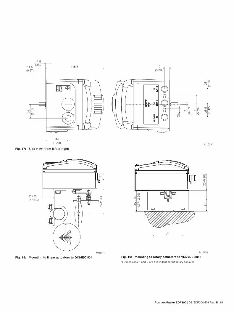
Fig. 17: Side view (from left to right)
Change from one to two columns
M10134
75
(2.9
5)30 / 53
(1.18 / 2.09)
Fig. 18: Mounting to linear actuators to DIN/IEC 534
M10135
B*
A*
45
-7
5
(1.7
7-
2.9
5)
25
(0.9
8)
Fig. 19: Mounting to rotary actuators to VDI/VDE 3845
*) Dimensions A and B are dependent on the rotary actuator
Change from two to one column

PositionMaster EDP300 Electro-Pneumatic Positioner
16 DS/EDP300-EN Rev. B | PositionMaster EDP300
Remote sensor dimensions (aluminum housing)
All dimensions in mm (inch)
Fig. 20: Top view
Fig. 21: Front and rear views 1 Threaded hole M8 (10 mm (0.39 inch) deep) | 2 Threaded hole M6 (8 mm deep (0.31 inch)) | 3 Sensor shaft (shown enlarged)
M10242
14,5
(0.5
7)
1 (0.0
4)
Ø 8 (0.31) h9
M10243
25 (0.9
8)
50 (1.9
7)
65 (2.5
6)
104,5 (4.11)
23 (0.91)
7 +/- 0,1
0.0039)(0.28 +/-
8
- 0
,01
5
(0.3
2 -
0.0
00
59
)
58 (2.28)50
( 1. 9
7)
110,75 (4.36)
Ø 26 (1.02)
25
(0.9
8)
89,5
(3.5
2)
168,5 (6.63)
45°
12
3
PositionMaster EDP300 | DS/EDP300-EN Rev. B 17
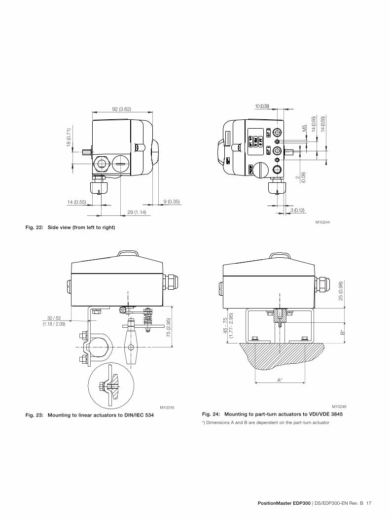
Fig. 22: Side view (from left to right)
Change from one to two columns
M10245
75
(2
.95
)30 / 53
(1.18 / 2.09)
Fig. 23: Mounting to linear actuators to DIN/IEC 534
M10246
B*
A*
45
- 7
5
(1.7
7-
2.9
5)
25
(0
.98
)
Fig. 24: Mounting to part-turn actuators to VDI/VDE 3845
*) Dimensions A and B are dependent on the part-turn actuator
Change from two to one column
M10244
14 (0.55)
29 (1.14)
18
(0
.71
)
92 (3.62)
9 (0.35)
14
(0.5
5)
14
(0.5
5)
2
(0.0
8)
3 (0.12)
10 (0.39)
M5

PositionMaster EDP300 Electro-Pneumatic Positioner
18 DS/EDP300-EN Rev. B | PositionMaster EDP300
Electrical connections
PositionMaster EDP300 with remote sensor The PositionMaster EDP300 version with remote sensor includes an adjusted unit with two housings. Housing 1 (EDP300 control unit) contains the electronics and pneumatics along with the following options (where applicable): • Analog position feedback • Digital position feedback • Shutdown module • Universal input Housing 2 (EDP300 remote sensor) contains the position sensor and is suitable for mounting on linear or part-turn actuators. The following options can be installed if required: • Optical position indicator • Mechanical feedback contacts (proximity switch or microswitch design). The two housings can be or are connected to a shielded 3-wire cable. The maximum cable length is 10 m. For Housing 1 (control unit) an attachment kit is available for pipe and wall mounting (see Accessories).
M10830
2 1 7 6 5
3 4
8
Fig. 25: EDP300 control unit with remote sensor 1 Housing 1 (control unit) | 2 Setpoint signal | 3 Connection cable | 4 Housing 2 (remote sensor) | 5 Pneumatic output 2 | 6 Pneumatic output 1 | 7 Supply air | 8 Pneumatic drive

PositionMaster EDP300 | DS/EDP300-EN Rev. B 19
Optionally, both housings of the “EDP300 stainless steel remote sensor” design are available in stainless steel. The housing dimensions are identical in this case - and the attachment kits are suitable for all versions.
M10831
Remote - Sensor
2 1 7 6 5
3 4
8
Fig. 26: EDP300 control unit made of stainless steel with EDP300 remote sensor made of stainless steel 1 Housing 1 (control unit) | 2 Setpoint | 3 Connection cable | 4 Housing 2 (remote sensor) | 5 Pneumatic output 2 | 6 Pneumatic output 1 | 7 Supply air | 8 Pneumatic drive
M108325 61 2 3 4
Fig. 27: Electrical connection 1 EDP300 control unit | 2 Remote sensor connection cable no. 3 | 3 Remote sensor connection cable no. 2 | 4 Remote sensor connection cable no. 1 | 5 Shielding | 6 EDP300 remote sensor

PositionMaster EDP300 Electro-Pneumatic Positioner
20 DS/EDP300-EN Rev. B | PositionMaster EDP300
PositionMaster EDP300 for external remote sensor
In the PositionMaster EDP300 design for remote sensor, the positioner is supplied without position detection. The housing (EDP300 control unit) contains the electronics and pneumatics along with the following options (where applicable): • Analog position feedback • Digital position feedback • Shutdown module • Universal input The EDP300 for remote sensor can be connected to any position sensor (4 … 80 kohms). The length of the shielded 3-core cable must be a maximum of 10 m. The installation and commissioning is carried out according to the respective chapters in the operating instructions. For the housing (EDP300 control unit) an attachment kit is available for pipe and wall mounting. (See Accessories).
M10833
2 1 7 6 5
3 4
8
Fig. 28: EDP300 control unit for remote sensor 1 Housing (control Unit) | 2 Setpoint signal | 3 Connection cable | 4 External remote sensor | 5 Pneumatic output 2 | 6 Pneumatic output 1 | 7 Supply air | 8 Pneumatic drive
M108345 61 2 3 4
Fig. 29: Electrical connection 1 EDP300 control unit | 2 Remote sensor connection cable No. 3 | 3 Remote sensor connection cable No. 2 | 4 Remote sensor connecting cable no. 1 | 5 Shielding | 6 External remote sensor
PositionMaster EDP300 | DS/EDP300-EN Rev. B 21
Terminal connection diagrams
M10835
+11 -12 +81-82 +83 -84 +51 1-52 2
AD
+41 3-42 +31 -32 +85 +21-86 -22
24 V
DC
(20 V
... 3
0 V
)
4 ... 2
0 m
A
L =
< 1
mA
; H
= >
2 m
A
5 ... 30 V
DC
L =
< 1
mA
; H
= >
2 m
A
5..
.30
VD
C
4 k
Ohm
... 8
0 k
Ohm
L =
< 1
mA
; H
= >
2 m
A
5 ... 30 V
DC
24 V
DC
(12 ... 3
0 V
)
4 ... 2
0 m
A
AI DI DO SW 2 SW 1 AO UAI
A
4 ... 2
0 m
A
10 ... 3
0 V
DC
1 2 3 4 5 6 7 8
B
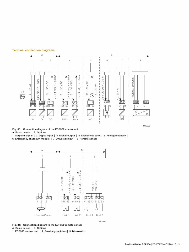
Fig. 30: Connection diagram of the EDP300 control unit A Basic device | B Options 1 Setpoint signal | 2 Digital input | 3 Digital output | 4 Digital feedback | 5 Analog feedback | 6 Emergency shutdown module | 7 Universal input | 8 Remote sensor
M10836
+51 -52 +41 -42
L =
< 1
mA
; H
= >
2 m
A
5 ... 11 V
DC
Limit 1 Limit 2
L =
< 1
mA
; H
= >
2 m
A
5 ... 1
1 V
DC
1 2 3 51 52 5341 42 43
max. 24 V
max. 2 A
Limit 1 Limit 2
A
1
Position Sensor
2 3
B
Fig. 31: Connection diagram to the EDP300 remote sensor A Basic device | B Options 1 EDP300 control unit | 2 Proximity switches | 3 Microswitch
PositionMaster EDP300 Electro-Pneumatic Positioner
22 DS/EDP300-EN Rev. B | PositionMaster EDP300
Change from one to two columns
Technical Data
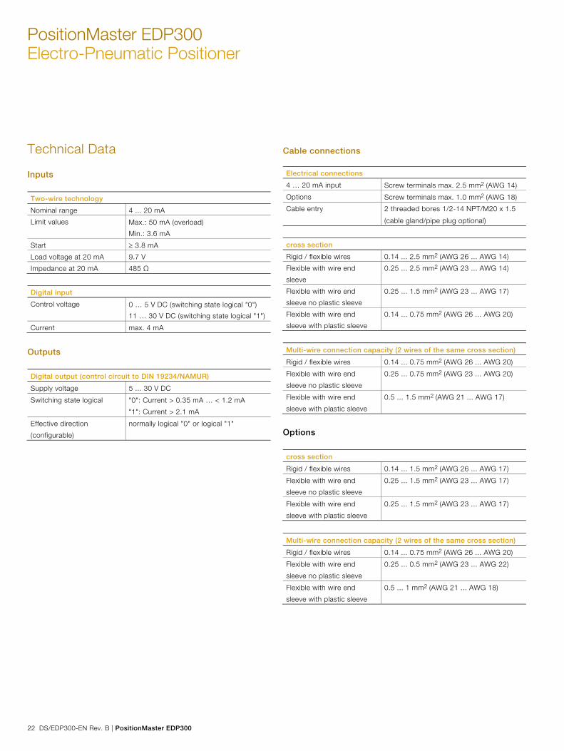
Inputs Two-wire technology
Nominal range 4 ... 20 mA
Limit values Max.: 50 mA (overload)
Min.: 3.6 mA
Start 3.8 mA
Load voltage at 20 mA 9.7 V
Impedance at 20 mA 485 Ω
Digital input
Control voltage 0 … 5 V DC (switching state logical "0")
11 … 30 V DC (switching state logical "1")
Current max. 4 mA
Outputs Digital output (control circuit to DIN 19234/NAMUR)
Supply voltage 5 ... 30 V DC
Switching state logical "0": Current > 0.35 mA … < 1.2 mA
"1": Current > 2.1 mA
Effective direction
(configurable)
normally logical "0" or logical "1"
Cable connections Electrical connections
4 … 20 mA input Screw terminals max. 2.5 mm2 (AWG 14)
Options Screw terminals max. 1.0 mm2 (AWG 18)
Cable entry 2 threaded bores 1/2-14 NPT/M20 x 1.5
(cable gland/pipe plug optional)
cross section
Rigid / flexible wires 0.14 ... 2.5 mm2 (AWG 26 ... AWG 14)
Flexible with wire end
sleeve
0.25 ... 2.5 mm2 (AWG 23 ... AWG 14)
Flexible with wire end
sleeve no plastic sleeve
0.25 ... 1.5 mm2 (AWG 23 ... AWG 17)
Flexible with wire end
sleeve with plastic sleeve
0.14 ... 0.75 mm2 (AWG 26 ... AWG 20)
Multi-wire connection capacity (2 wires of the same cross section)
Rigid / flexible wires 0.14 ... 0.75 mm2 (AWG 26 ... AWG 20)
Flexible with wire end
sleeve no plastic sleeve
0.25 ... 0.75 mm2 (AWG 23 ... AWG 20)
Flexible with wire end
sleeve with plastic sleeve
0.5 ... 1.5 mm2 (AWG 21 ... AWG 17)
Options cross section
Rigid / flexible wires 0.14 ... 1.5 mm2 (AWG 26 ... AWG 17)
Flexible with wire end
sleeve no plastic sleeve
0.25 ... 1.5 mm2 (AWG 23 ... AWG 17)
Flexible with wire end
sleeve with plastic sleeve
0.25 ... 1.5 mm2 (AWG 23 ... AWG 17)
Multi-wire connection capacity (2 wires of the same cross section)
Rigid / flexible wires 0.14 ... 0.75 mm2 (AWG 26 ... AWG 20)
Flexible with wire end
sleeve no plastic sleeve
0.25 ... 0.5 mm2 (AWG 23 ... AWG 22)
Flexible with wire end
sleeve with plastic sleeve
0.5 ... 1 mm2 (AWG 21 ... AWG 18)
PositionMaster EDP300 | DS/EDP300-EN Rev. B 23
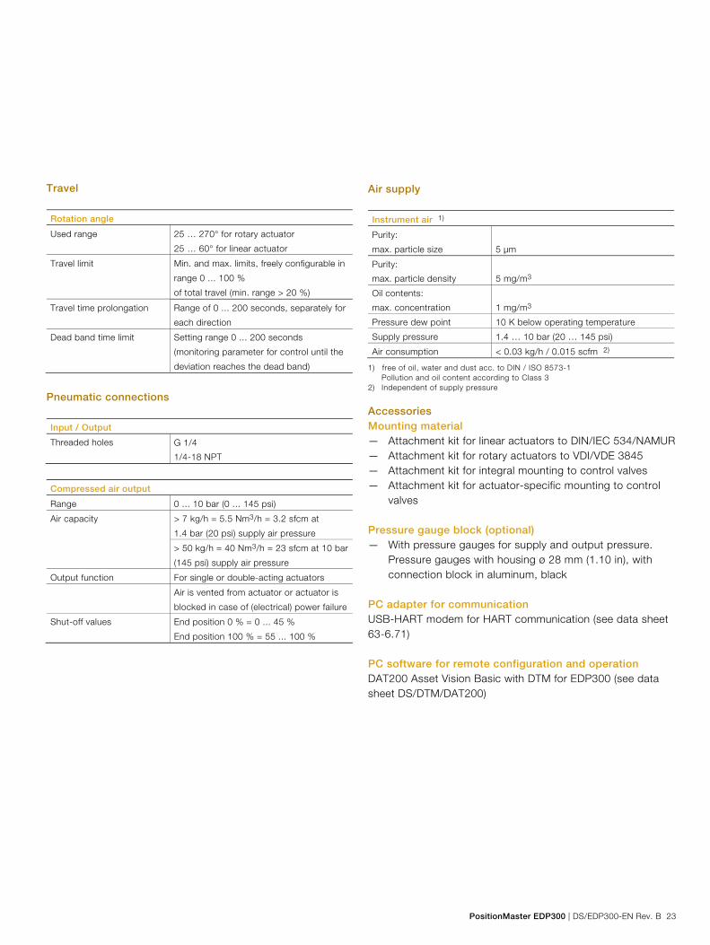
Travel Rotation angle
Used range 25 … 270° for rotary actuator
25 … 60° for linear actuator
Travel limit Min. and max. limits, freely configurable in
range 0 ... 100 %
of total travel (min. range > 20 %)
Travel time prolongation Range of 0 ... 200 seconds, separately for
each direction
Dead band time limit Setting range 0 ... 200 seconds
(monitoring parameter for control until the
deviation reaches the dead band)
Pneumatic connections Input / Output
Threaded holes G 1/4
1/4-18 NPT
Compressed air output
Range 0 ... 10 bar (0 ... 145 psi)
Air capacity > 7 kg/h = 5.5 Nm3/h = 3.2 sfcm at
1.4 bar (20 psi) supply air pressure
> 50 kg/h = 40 Nm3/h = 23 sfcm at 10 bar
(145 psi) supply air pressure
Output function For single or double-acting actuators
Air is vented from actuator or actuator is
blocked in case of (electrical) power failure
Shut-off values End position 0 % = 0 ... 45 %
End position 100 % = 55 ... 100 %
Air supply Instrument air 1)
Purity:
max. particle size 5 μm
Purity:
max. particle density 5 mg/m3
Oil contents:
max. concentration 1 mg/m3
Pressure dew point 10 K below operating temperature
Supply pressure 1.4 … 10 bar (20 … 145 psi)
Air consumption < 0.03 kg/h / 0.015 scfm 2)
1) free of oil, water and dust acc. to DIN / ISO 8573-1 Pollution and oil content according to Class 3 2) Independent of supply pressure
Accessories Mounting material — Attachment kit for linear actuators to DIN/IEC 534/NAMUR — Attachment kit for rotary actuators to VDI/VDE 3845 — Attachment kit for integral mounting to control valves — Attachment kit for actuator-specific mounting to control
valves Pressure gauge block (optional) — With pressure gauges for supply and output pressure.
Pressure gauges with housing ø 28 mm (1.10 in), with connection block in aluminum, black
PC adapter for communication USB-HART modem for HART communication (see data sheet 63-6.71) PC software for remote configuration and operation DAT200 Asset Vision Basic with DTM for EDP300 (see data sheet DS/DTM/DAT200)

PositionMaster EDP300 Electro-Pneumatic Positioner
24 DS/EDP300-EN Rev. B | PositionMaster EDP300
Housing Material / Degree of protection
Aluminum with
≤ 0.1% copper
Optional stainless steel 1.4404 (316L)
Degree of protection IP 65 / NEMA 4X (NEMA 4X does not
permit overhead mounting)
Surface / color (aluminum housing only)
Dipping varnish With epoxy resin, stove-hardened
Housing varnished black RAL 9005
RAL 9002
Weight
Aluminum 2.4 kg (5.29 lb)
Stainless steel 1.4404
(316L)
5.5 kg (12.13 lb)
Mounting orientation Any
Transmission data and influences Output Y1
Increasing setpoint signal 0 ... 100 %
Increasing pressure at output
Decreasing setpoint signal 0 ... 100 %
Decreasing pressure at output
Action (setpoint signal)
Increasing setpoint 4 ... 20 mA
= actuator position 0 ... 100 %
Decreasing setpoint 20 ... 4 mA
= actuator position 0 ... 100 %
Characteristic curve (travel = f {setpoint signal})
Linear Equal percentage 1:25 or 1:50 or 25:1 or
50:1 1)
Deviation < 0.5 %
Configurable zone 0 ... 100 %,
Configurable dead zone 0.1 ... 10 %,
Resolution (A/D conversion) > 16,000 steps
Sample rate 20 ms
Ambient temperature
influence
< 0.5 % for each 10 K
Influence of vibration < 1 % to 10 g and 80 Hz
1) Freely configurable with 20 reference points
Seismic vibration Meets requirements of DIN/IEC 60068-3-3 Class III for strong and strongest earthquakes. Influence of mounting orientation Not measurable. Noise emissions Max. 100 db (A) Noise-reduced version max. 85 db (A)
Environmental capabilities Ambient temperature range
For operation, storage, and
transport
-40 ... 85 °C (-40 ... 185 °F)
When using proximity
switches SJ2-S1N (NO)
-25 ... 85 °C (-13 ... 185 °F)
Relative humidity
Operational with housing
closed and air supply
switched on
95 % (annual average), condensation
permissible
Transport and storage 75 % (annual average)
Explosion protection FM certificate 3043773 IS, C1. I, Div 1, Grp. A, B, C, D, T4 or T6 IS, C1. II, Div 1, Grp. E, F, G, T4 or T6 IS, C1. III, Div 1, T4 or T6 Class I Zone 0, AEx ia IIC, T4 or T6 NI,CI. I,Div.2, Grp. A, B, C, D, T4 or T6 NI,CI. II,Div.2, Grp. E, F, G, T4 or T6 NI,CI. III,Div.2, T4 or T6 Class I Zone 2, IIC, T4 or T6 Enclosure type 4X CSA Certification 2419437 Class I, Division 1, Groups A, B, C, D; Class II, Division 1, Groups E, F, G; Class III T4 Ex ia IIC T4 Class I, Zone =, AEx ia IIC T4
Change from two to one column
PositionMaster EDP300 | DS/EDP300-EN Rev. B 25
Change from one to two columns
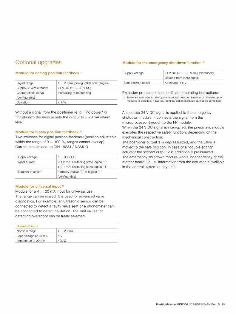
Optional upgrades
Module for analog position feedback 1) Signal range 4 ... 20 mA (configurable split ranges)
Supply, 2-wire circuitry 24 V DC (10 ... 30 V DC)
Characteristic curve
(configurable)
Increasing or decreasing
Deviation < 1 %
Without a signal from the positioner (e. g., "no power" or "initializing") the module sets the output to > 20 mA (alarm level) Module for binary position feedback 1) Two switches for digital position feedback (position adjustable within the range of 0 ... 100 %, ranges cannot overlap) Current circuits acc. to DIN 19234 / NAMUR Supply voltage 5 ... 30 V DC
Signal current < 1.2 mA: Switching state logical "0"
> 2.1 mA: Switching state logical "1"
Direction of action normally logical "0" or logical "1"
(configurable)
Module for universal input 1) Module for a 4 … 20 mA input for universal use. The range can be scaled. It is used for advanced valve diagnostics. For example, an ultrasonic sensor can be connected to detect a faulty valve seat or a phonometer can be connected to detect cavitation. The limit values for detecting overshoot can be freely selected. Universal input
Nominal range 4 ... 20 mA
Load voltage at 20 mA 8 V
Impedance at 20 mA 400 Ω
Module for the emergency shutdown function 1) Supply voltage 24 V DC (20 ... 30 V DC) (electrically
isolated from input signal)
Safe position active At voltage < 5 V
Explosion protection: see certificate (operating instructions)
1) There are two slots for the option modules. Any combination of different option modules is possible. However, identical option modules cannot be combined.
A separate 24 V DC signal is applied to the emergency shutdown module; it connects the signal from the microprocessor through to the I/P module. When the 24 V DC signal is interrupted, the pneumatic module executes the respective safety function, depending on the mechanical construction: The positioner output 1 is depressurized, and the valve is moved to the safe position. In case of a "double-acting" actuator the second output 2 is additionally pressurized. The emergency shutdown module works independently of the mother board, i.e., all information from the actuator is available in the control system at any time.
PositionMaster EDP300 Electro-Pneumatic Positioner
26 DS/EDP300-EN Rev. B | PositionMaster EDP300
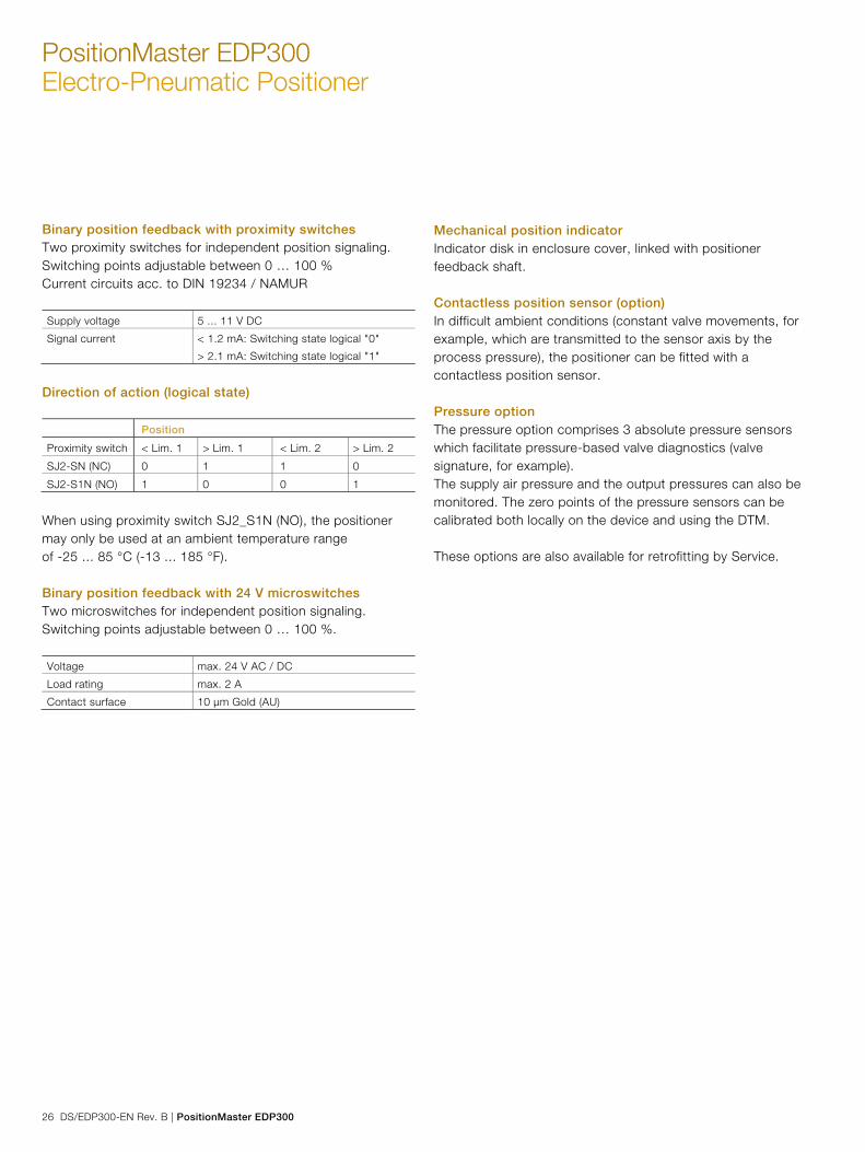
Binary position feedback with proximity switches Two proximity switches for independent position signaling. Switching points adjustable between 0 … 100 % Current circuits acc. to DIN 19234 / NAMUR Supply voltage 5 ... 11 V DC
Signal current < 1.2 mA: Switching state logical "0"
> 2.1 mA: Switching state logical "1"
Direction of action (logical state) Position
Proximity switch < Lim. 1 > Lim. 1 < Lim. 2 > Lim. 2
SJ2-SN (NC) 0 1 1 0
SJ2-S1N (NO) 1 0 0 1
When using proximity switch SJ2_S1N (NO), the positioner may only be used at an ambient temperature range of -25 ... 85 °C (-13 ... 185 °F). Binary position feedback with 24 V microswitches Two microswitches for independent position signaling. Switching points adjustable between 0 … 100 %. Voltage max. 24 V AC / DC
Load rating max. 2 A
Contact surface 10 μm Gold (AU)
Mechanical position indicator Indicator disk in enclosure cover, linked with positioner feedback shaft. Contactless position sensor (option) In difficult ambient conditions (constant valve movements, for example, which are transmitted to the sensor axis by the process pressure), the positioner can be fitted with a contactless position sensor. Pressure option The pressure option comprises 3 absolute pressure sensors which facilitate pressure-based valve diagnostics (valve signature, for example). The supply air pressure and the output pressures can also be monitored. The zero points of the pressure sensors can be calibrated both locally on the device and using the DTM. These options are also available for retrofitting by Service.
Change from two to one column
PositionMaster EDP300 | DS/EDP300-EN Rev. B 27
Change from one to two columns
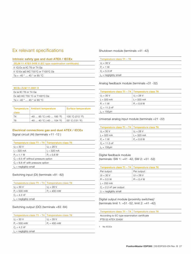
Ex relevant specifications
Intrinsic safety gas and dust ATEX / IECEx
ZELM 11 ATEX 0456 X (EC type examination certificate)
II 1G Ex ia IIC T6 or T4 Ga
II 1D Ex iaD IIIC T55°C or T100°C Da
Ta = -40 ° … 40 ° or 85 °C
IECEx ZLM 11.0001 X
Ex ia IIC T6 or T4 Ga
Ex iaD IIIC T55 °C or T100°C Da
Ta = -40 ° … 40 ° or 85 °C
Temperature
class
Ambient temperature Surface temperature
T4 -40 … 85 °C (-40 … 185 °F) 100 °C (212 °F)
T6 -40 … 40 °C (-40 … 104 °F) 55° C (131 °F)
Electrical connections gas and dust ATEX / IECEx
Signal circuit (AI) (terminals +11 -12 ) Temperature class T1 – T4 Temperature class T6
Ui = 30 V Ui = 28 V
Ii = 320 mA Ii = 320 mA
Pi = 1.1 W Pi = 0.8 W
Ci = 6.5 nF without pressure option
Ci = 8.8 nF with pressure option
Li = negligibly small
Switching input (DI) (terminals +81 -82) Temperature class T1 – T4 Temperature class T6
Ui = 30 V Ui = 28 V
Pi = 500 mW Pi = 400 mW
Ci = 4.2 nF
Li = negligibly small
Switching output (DO) (terminals +83 -84) Temperature class T1 – T4 Temperature class T6
Ui = 30 V Ui = 28 V
Pi = 500 mW Pi = 400 mW
Ci = 4.2 nF
Li = negligibly small
Shutdown module (terminals +41 -42) Temperature class T1 – T6
Ui = 30 V
Pi = 1 W
Ci = 5.3 nF
Li = negligibly small
Analog feedback module (terminals +31 -32) Temperature class T1 – T4 Temperature class T6
Ui = 30 V Ui = 28 V
Ii = 320 mA Ii = 320 mA
Pi = 1 W Pi = 0.8 W
Ci = 11.3 nF
Li = 150μH
Universal analog input module (terminals +21 -22) Temperature class T1 – T4 Temperature class T6
Ui = 30 V Ui = 28 V
Ii = 320 mA Ii = 320 mA
Pi = 1 W Pi = 0.8 W
Ci = 11.3 nF
Li = 150μH
Digital feedback module (terminals: SW 1: +41 -42, SW 2: +51 -52) Temperature class T1 – T4 Temperature class T6
Per output: Per output:
Ui = 30 V Ui = 28 V
Pi = 0.5 W Pi = 0.4 W
Ii = 250 mA
Ci = 2.2 nF per output
Li = negligibly small
Digital output module (proximity switches)1 (terminals limit 1: +51 -52, limit 2: +41 -42) Temperature class T1 – T4 Temperature class T6
According to EC type examination certificate
PTB 00 ATEX 2049X
1 No IECEx

PositionMaster EDP300 Electro-Pneumatic Positioner
28 DS/EDP300-EN Rev. B | PositionMaster EDP300
Equipment in type of protection "n" or device dust ignition protection through housing "tb" ZELM 11 ATEX 0456 X (EC type examination certificate)
II 3G Ex nA IIC T6 or T4 Gc
II 2D Ex tb IIIC T55°C or T100°C Db
Ta = -40 ° … 40 ° or 80
IECEx ZLM 11.0001 X
Ex nA IIC T6 or T4 Gc
Ex tb IIIC T55 °C or T100°C Db
Ta = -40 ° … 40 ° or 80
Temperature
class
Ambient temperature Surface temperature
T4 -40 … 80 °C (-40 … 176 °F) 100 °C (212 °F)
T6 -40 … 40 °C (-40 … 104 °F) 55° C (131 °F)
Electrical connections non-sparking ATEX/IECEx
Equipment in type of protection "n" or device dust ignition protection through housing "tb" Signal circuit (AI) (terminals +11 -12): IN ≤ 22 mA Umax ≤ 30 V Switching input (DI) (terminals +81 -82): UN ≤ 30 V Switching output (DO) (terminals +83 -84): UN ≤ 30 V Shutdown module (terminals +41 -42): UN ≤ 30 V
Analog feedback module (UAI) (terminals +31 -32) IN ≤ 22 mA UN ≤ 30 V Universal analog input module (terminals +21 -22) IN ≤ 22 mA Umax ≤ 30 V Digital feedback module (terminals: SW 1: +41 -42, SW 2: +51 -52) Per output: UN ≤ 30 V Digital output module (proximity switches) (terminals limit 1: +51 -52, limit 2: +41 -42) Per output: IN ≤ 25 mA UN ≤ 16 V When using proximity switch SJ2_S1N (NO), the positioner may only be used at an ambient temperature range of -25 ... 80 °C (-13 ... 176 °F).
Change from two to one column
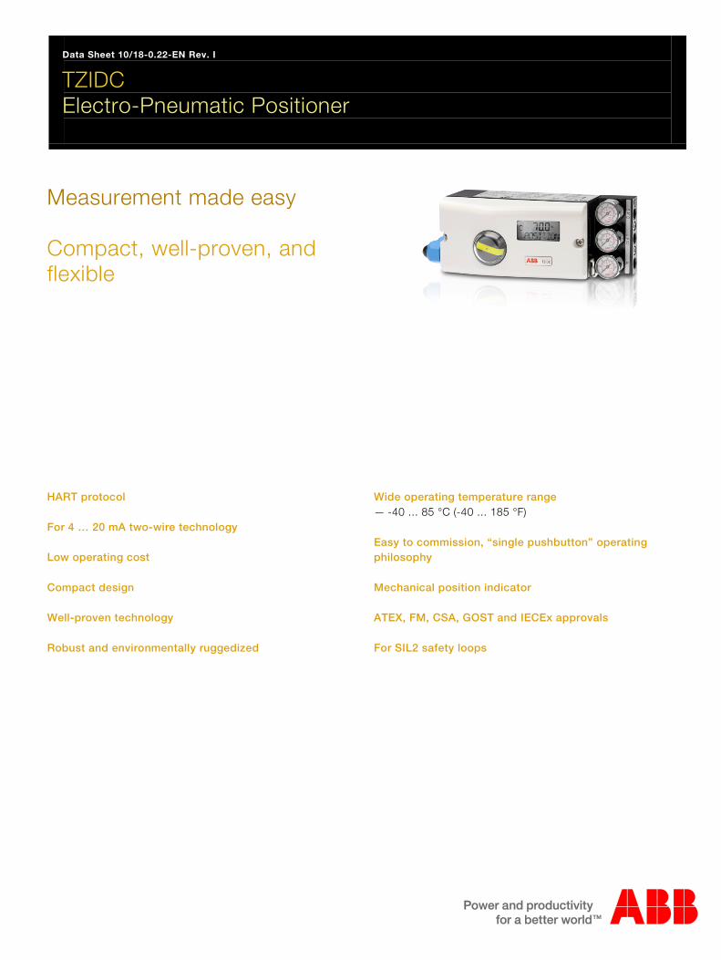
Data Sheet 10/18-0.22-EN Rev. I
TZIDC Electro-Pneumatic Positioner
Contents
Measurement made easy Compact, well-proven, and flexible
HART protocol For 4 … 20 mA two-wire technology Low operating cost Compact design Well-proven technology Robust and environmentally ruggedized
Wide operating temperature range — -40 ... 85 °C (-40 ... 185 °F) Easy to commission, “single pushbutton” operating philosophy Mechanical position indicator ATEX, FM, CSA, GOST and IECEx approvals For SIL2 safety loops

Electro-Pneumatic Positioner TZIDC 10/18-0.22-EN for 4 ... 20 mA two-wire technology
3
1 Description Change from one to two col umns
The TZIDC is an electronically configurable positioner with communication capabilities designed for mounting to pneumatic linear or rotary actuators. It features a small and compact design, a modular construction, and an excellent cost-performance ratio. Fully automatic determination of the control parameters and adaptation to the final control element yield considerable time savings and an optimal control behavior.
1.1 Pneumatics a
An I/P module with subsequent pneumatic amplifier is used to control the pneumatic actuator. The well-proven I/P module proportionally converts the permanent electrical setpoint signal from the CPU into a pneumatic signal used to adjust a 3/3-way valve. The air flow for pressurizing or depressurizing the actuator is continuously adjusted. As a result, excellent control is achieved. When reaching the set point, the 3/3-way valve is closed in center position to minimize the air consumption. Four different pneumatics versions are available: for single-acting or double-acting actuators, each with “fail-safe” or “fail-freeze” function.
1.1.1 “Fail-safe” function
If the electrical power supply fails, the positioner output 1 is depressurized, and the pneumatic actuator’s return spring moves the valve to the defined safe position. In case of a double-acting actuator the second output 2 is additionally pressurized.
1.1.2 “Fail-freeze” function
If the electrical power supply should fail, the positioner output 1 (and 2, if applicable) is closed and the pneumatic actuator stops (“freezes”) the valve in the current position. If compressed air supply should fail, the positioner depressurizes the actuator.
1.2 Operation
The positioner has a built-in operating panel providing a 2-line LCD and 4 pushbuttons for optimal local configuration, commissioning and operational monitoring. Alternatively, the appropriate configuration program and the available communication option can be used.
1.3 Communication
The standard TZIDC model has a local communication interface (LKS connector). Additionally, a “HART communication” option for communication via the 20 mA signal is available. Both communications are based on the HART Protocol.
1.4 Inputs and outputs
In addition to its input for the analog position set point the TZIDC positioner is equipped with a digital input which can be used to activate various protective functions in the device via the process control system. A digital output allows you to output collective alarms or fault messages.
1.5 Modular design q
TheTZIDC basic model can be enhanced at any time by retrofitting optional equipment. Option modules for analog or digital position feedback or a shutdown-module can be installed. Additionally, a mechanical position indicator, proximity switches or 24 V microswitches are available for indicating the position independently of the mother board function.
Change from one to two col umns
Electro-Pneumatic Positioner TZIDC 10/18-0.22-EN for 4 ... 20 mA two-wire technology
4
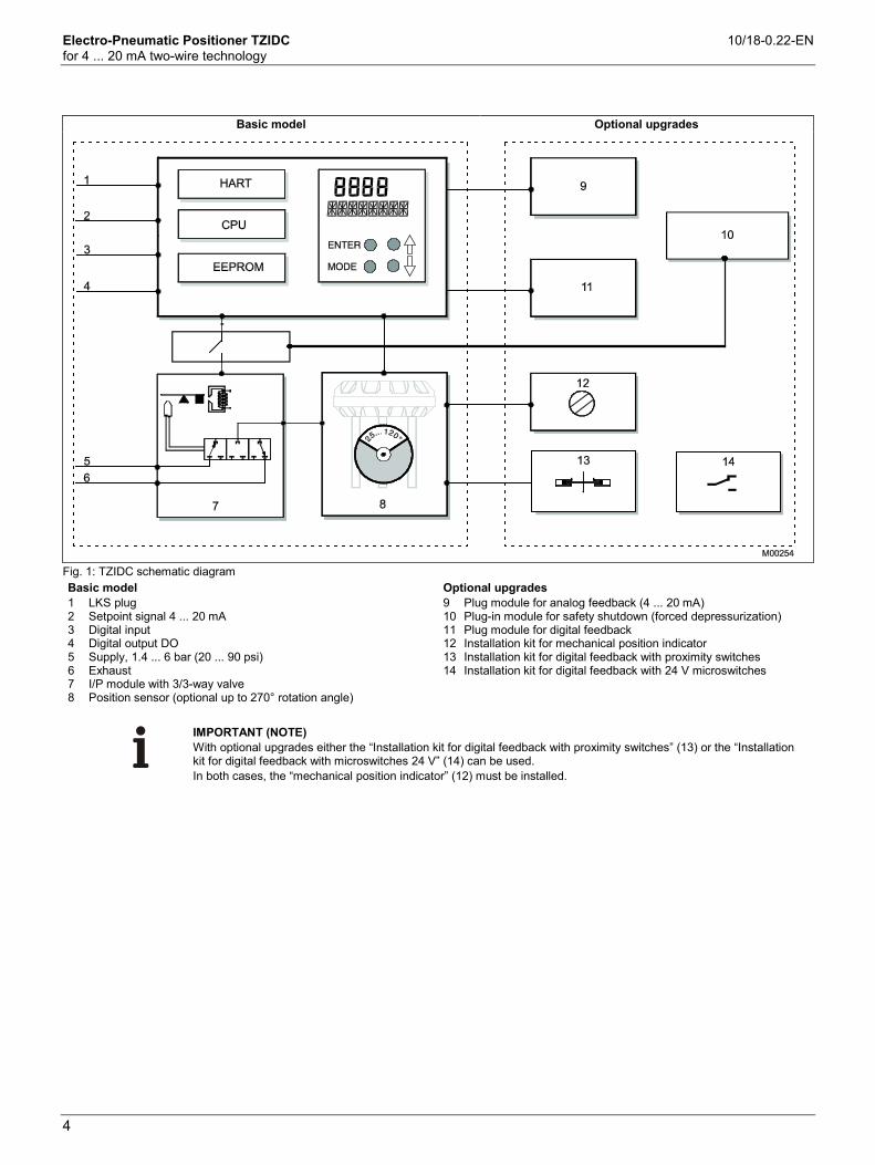
Basic model Optional upgrades
Fig. 1: TZIDC schematic diagram Basic model Optional upgrades 1 LKS plug 2 Setpoint signal 4 ... 20 mA 3 Digital input 4 Digital output DO 5 Supply, 1.4 ... 6 bar (20 ... 90 psi) 6 Exhaust 7 I/P module with 3/3-way valve 8 Position sensor (optional up to 270° rotation angle)
9 Plug module for analog feedback (4 ... 20 mA) 10 Plug-in module for safety shutdown (forced depressurization) 11 Plug module for digital feedback 12 Installation kit for mechanical position indicator 13 Installation kit for digital feedback with proximity switches 14 Installation kit for digital feedback with 24 V microswitches
IMPORTANT (NOTE) With optional upgrades either the “Installation kit for digital feedback with proximity switches” (13) or the “Installation kit for digital feedback with microswitches 24 V” (14) can be used. In both cases, the “mechanical position indicator” (12) must be installed.
Electro-Pneumatic Positioner TZIDC 10/18-0.22-EN for 4 ... 20 mA two-wire technology
5
2 Mounting versions Change from one to two col umns
2.1 To linear actuators in accordance with the standard
Lateral attachment is in accordance with DIN / IEC 534 (lateral attachment to NAMUR). The required attachment kit is a complete set of attachment material, but does not include the screwed pipe connections and air pipes.
2.2 To rotary actuators in accordance with the standard
This attachment is designed for mounting according to the standard VDI/VDE 3845. The attachment kit consists of a console with mounting screws for mounting on a rotary actuator. The adapter for coupling the positioner feedback shaft to the actuator shaft has to be ordered separately. Screwed pipe connections and air pipes have to be provided on site.
2.3 Integral mounting to control valves
The TZIDC positioner featuring standard pneumatic action is available as an option for integral mounting. The required holes are found at the back of the device. The benefit of this design is that the point for mechanical stroke measurement is protected and that the positioner and actuator are linked internally. No external tubing is required.
2.4 Special actuator-specific mounting
In addition to the mounting methods described above, there are special actuator-specific attachments. Please contact us for details.
Change from one to two col umns

Electro-Pneumatic Positioner TZIDC 10/18-0.22-EN for 4 ... 20 mA two-wire technology
6
Fig. 2: Mounting options 1 Mounting to linear actuators acc. to DIN / IEC 534 2 Mounting to rotary actuators to VDI / VDE 3845
3 Integral mounting to control valves 4 Integral mounting to control valves by using an adapter panel
Electro-Pneumatic Positioner TZIDC 10/18-0.22-EN for 4 ... 20 mA two-wire technology
7
3 Operation Change from one to two col umns A
3.1 General
Microprocessor-based position control in the TZIDC provides for optimal results. The positioner features high-precision control functions and high operational reliability. Due to their elaborate structure and easy accessibility, the device parameters can be quickly adapted to the respective application.
The total range of parameters includes: - Operating parameters - Adjustment parameters - Monitoring parameters - Diagnosis parameters - Maintenance parameters
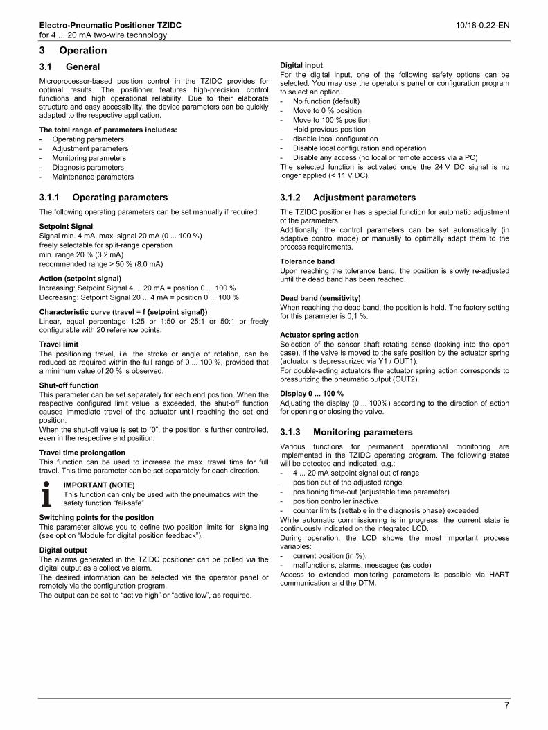
3.1.1 Operating parameters
The following operating parameters can be set manually if required:
Setpoint Signal Signal min. 4 mA, max. signal 20 mA (0 ... 100 %) freely selectable for split-range operation min. range 20 % (3.2 mA) recommended range > 50 % (8.0 mA)
Action (setpoint signal) Increasing: Setpoint Signal 4 ... 20 mA = position 0 ... 100 % Decreasing: Setpoint Signal 20 ... 4 mA = position 0 ... 100 %
Characteristic curve (travel = f {setpoint signal}) Linear, equal percentage 1:25 or 1:50 or 25:1 or 50:1 or freely configurable with 20 reference points.
Travel limit The positioning travel, i.e. the stroke or angle of rotation, can be reduced as required within the full range of 0 ... 100 %, provided that a minimum value of 20 % is observed.
Shut-off function This parameter can be set separately for each end position. When the respective configured limit value is exceeded, the shut-off function causes immediate travel of the actuator until reaching the set end position. When the shut-off value is set to “0”, the position is further controlled, even in the respective end position.
Travel time prolongation This function can be used to increase the max. travel time for full travel. This time parameter can be set separately for each direction.
IMPORTANT (NOTE) This function can only be used with the pneumatics with the safety function “fail-safe”.
Switching points for the position This parameter allows you to define two position limits for signaling (see option “Module for digital position feedback”).
Digital output The alarms generated in the TZIDC positioner can be polled via the digital output as a collective alarm. The desired information can be selected via the operator panel or remotely via the configuration program. The output can be set to “active high” or “active low”, as required.
Digital input For the digital input, one of the following safety options can be selected. You may use the operator’s panel or configuration program to select an option. - No function (default) - Move to 0 % position - Move to 100 % position - Hold previous position - disable local configuration - Disable local configuration and operation - Disable any access (no local or remote access via a PC) The selected function is activated once the 24 V DC signal is no longer applied (< 11 V DC).
3.1.2 Adjustment parameters
The TZIDC positioner has a special function for automatic adjustment of the parameters. Additionally, the control parameters can be set automatically (in adaptive control mode) or manually to optimally adapt them to the process requirements.
Tolerance band Upon reaching the tolerance band, the position is slowly re-adjusted until the dead band has been reached. Dead band (sensitivity) When reaching the dead band, the position is held. The factory setting for this parameter is 0,1 %. Actuator spring action Selection of the sensor shaft rotating sense (looking into the open case), if the valve is moved to the safe position by the actuator spring (actuator is depressurized via Y1 / OUT1). For double-acting actuators the actuator spring action corresponds to pressurizing the pneumatic output (OUT2).
Display 0 ... 100 % Adjusting the display (0 ... 100%) according to the direction of action for opening or closing the valve.
3.1.3 Monitoring parameters B
Various functions for permanent operational monitoring are implemented in the TZIDC operating program. The following states will be detected and indicated, e.g.: - 4 ... 20 mA setpoint signal out of range - position out of the adjusted range - positioning time-out (adjustable time parameter) - position controller inactive - counter limits (settable in the diagnosis phase) exceeded While automatic commissioning is in progress, the current state is continuously indicated on the integrated LCD. During operation, the LCD shows the most important process variables: - current position (in %), - malfunctions, alarms, messages (as code) Access to extended monitoring parameters is possible via HART communication and the DTM.

Electro-Pneumatic Positioner TZIDC 10/18-0.22-EN for 4 ... 20 mA two-wire technology
8
3.1.4 Diagnosis parameters
The diagnosis parameters of the TZIDC program inform the operator about the operating conditions of the valve. From this information the operator can derive which maintenance works are required, and when. Additionally, limit values can be defined for these parameters. When they are exceeded, an alarm is reported. The following values are e.g. determined: - Number of movements performed by the valve - Total travel The diagnosis parameters and limit values can be called up, set, and reset via HART communication, using the configuration program.
3.2 Operator panel
The TZIDC positioner’s operator panel with four pushbuttons allows for - operational monitoring - manual control - configuration - fully automatic commissioning The operator panel is protected by a cover which avoids unauthorized access to the operating elements.
3.2.1 Single-button commissioning
Commissioning the TZIDC positioner is especially easy. The standard Autoadjust function for automatic adaptation of the device parameters can be started by simply pressing a single front panel button, and without knowing parameterization details. Depending on the selected actuator type (linear or rotary), the displayed zero position is automatically adapted: - for linear actuators counter-clockwise (CTCLOCKW) - for rotary actuators clockwise (CLOCKW). Besides this standard function, a customized “Autoadjust” function is available. The function is launched either via the operator’s panel or HART communication.
3.2.2 Display
The information indicated by the 2-line LC display is permanently updated and adapted during operation, to inform the operator in an optimal way. During control operation (control with or without adaptation) the following TZIDC data can be called up by pressing the pushbuttons briefly: - Up button: Current setpoint (mA) - Down button: Temperature in device - Up + Down buttons: Current control deviation
Change from one to two col umns
Change from one to two col umns
Fig. 3: TZIDC with removed cover, view of the operator panel
Fig. 4: TZIDC operating elements and display
Change from one to two col umns
Electro-Pneumatic Positioner TZIDC 10/18-0.22-EN for 4 ... 20 mA two-wire technology
9
Kommuni kati on
4 Communication Change from one to two col umns
4.1 DTM
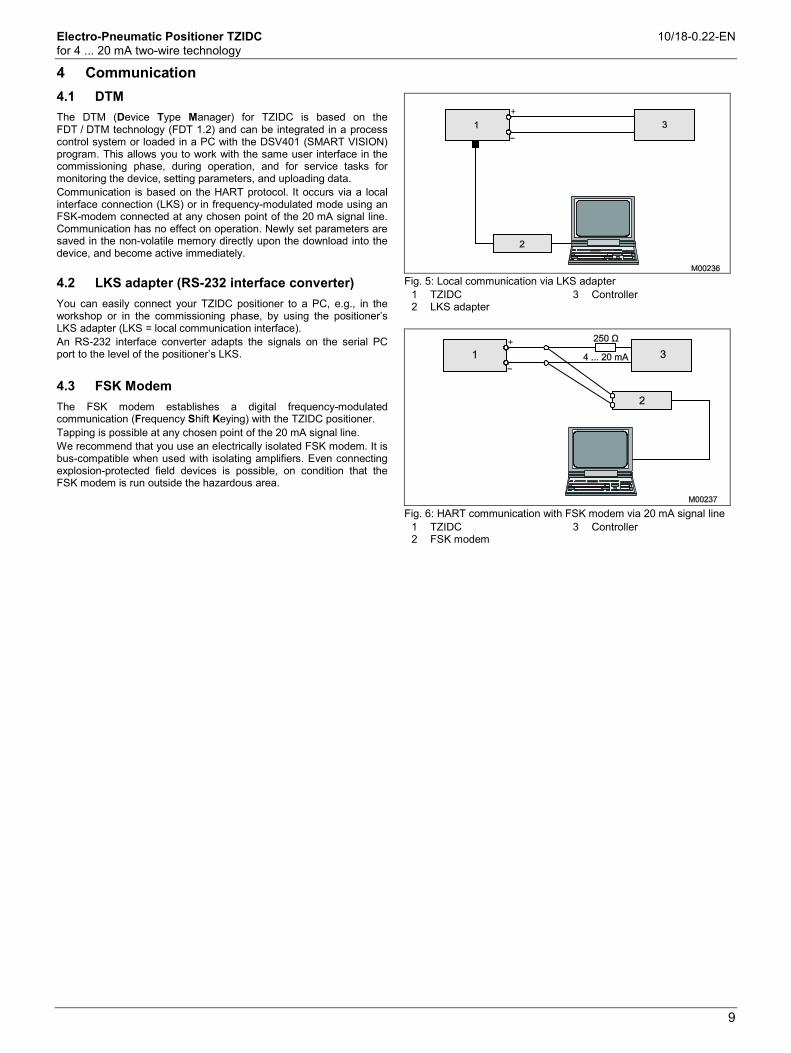
The DTM (Device Type Manager) for TZIDC is based on the FDT / DTM technology (FDT 1.2) and can be integrated in a process control system or loaded in a PC with the DSV401 (SMART VISION) program. This allows you to work with the same user interface in the commissioning phase, during operation, and for service tasks for monitoring the device, setting parameters, and uploading data. Communication is based on the HART protocol. It occurs via a local interface connection (LKS) or in frequency-modulated mode using an FSK-modem connected at any chosen point of the 20 mA signal line. Communication has no effect on operation. Newly set parameters are saved in the non-volatile memory directly upon the download into the device, and become active immediately.
4.2 LKS adapter (RS-232 interface converter)
You can easily connect your TZIDC positioner to a PC, e.g., in the workshop or in the commissioning phase, by using the positioner’s LKS adapter (LKS = local communication interface). An RS-232 interface converter adapts the signals on the serial PC port to the level of the positioner’s LKS.
4.3 FSK Modem
The FSK modem establishes a digital frequency-modulated communication (Frequency Shift Keying) with the TZIDC positioner. Tapping is possible at any chosen point of the 20 mA signal line. We recommend that you use an electrically isolated FSK modem. It is bus-compatible when used with isolating amplifiers. Even connecting explosion-protected field devices is possible, on condition that the FSK modem is run outside the hazardous area.
Fig. 5: Local communication via LKS adapter
1 TZIDC 2 LKS adapter
3 Controller
Fig. 6: HART communication with FSK modem via 20 mA signal line
1 TZIDC 2 FSK modem
3 Controller
Change from one to two col umns
Electro-Pneumatic Positioner TZIDC 10/18-0.22-EN for 4 ... 20 mA two-wire technology
10
5 Specifications Change from one to two col umns
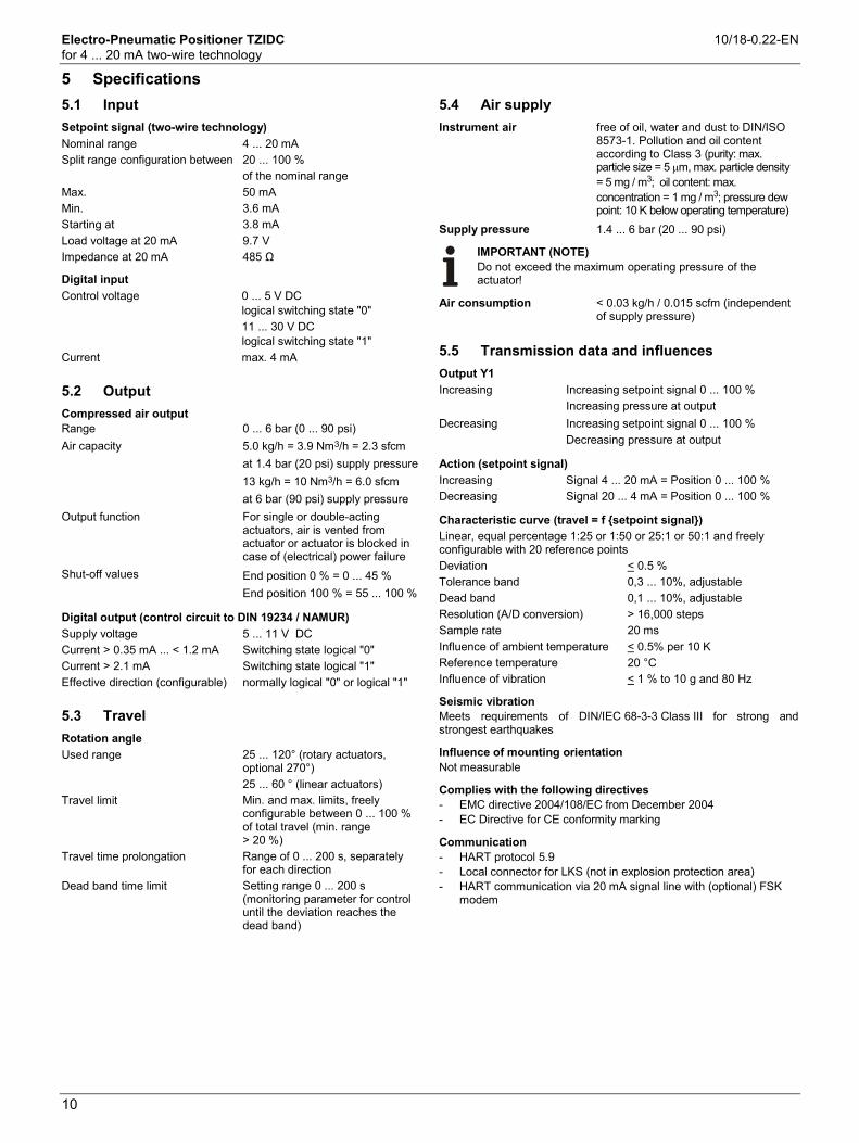
5.1 Input
Setpoint signal (two-wire technology) Nominal range 4 ... 20 mA Split range configuration between 20 ... 100 % of the nominal range Max. 50 mA Min. 3.6 mA Starting at 3.8 mA Load voltage at 20 mA 9.7 V Impedance at 20 mA 485 Ω
Digital input Control voltage 0 ... 5 V DC
logical switching state "0" 11 ... 30 V DC
logical switching state "1" Current max. 4 mA
5.2 Output
Compressed air output Range 0 ... 6 bar (0 ... 90 psi) Air capacity 5.0 kg/h = 3.9 Nm3/h = 2.3 sfcm at 1.4 bar (20 psi) supply pressure 13 kg/h = 10 Nm3/h = 6.0 sfcm at 6 bar (90 psi) supply pressure Output function For single or double-acting
actuators, air is vented from actuator or actuator is blocked in case of (electrical) power failure
Shut-off values End position 0 % = 0 ... 45 % End position 100 % = 55 ... 100 %
Digital output (control circuit to DIN 19234 / NAMUR) Supply voltage 5 ... 11 V DC Current > 0.35 mA ... < 1.2 mA Switching state logical "0" Current > 2.1 mA Switching state logical "1" Effective direction (configurable) normally logical "0" or logical "1"
5.3 Travel
Rotation angle Used range 25 ... 120° (rotary actuators,
optional 270°) 25 ... 60 ° (linear actuators) Travel limit Min. and max. limits, freely
configurable between 0 ... 100 % of total travel (min. range > 20 %)
Travel time prolongation Range of 0 ... 200 s, separately for each direction
Dead band time limit Setting range 0 ... 200 s (monitoring parameter for control until the deviation reaches the dead band)
5.4 Air supply
Instrument air free of oil, water and dust to DIN/ISO 8573-1. Pollution and oil content according to Class 3 (purity: max. particle size = 5 µm, max. particle density = 5 mg / m3; oil content: max. concentration = 1 mg / m3; pressure dew point: 10 K below operating temperature)
Supply pressure 1.4 ... 6 bar (20 ... 90 psi)
IMPORTANT (NOTE) Do not exceed the maximum operating pressure of the actuator!
Air consumption < 0.03 kg/h / 0.015 scfm (independent of supply pressure)
5.5 Transmission data and influences
Output Y1 Increasing Increasing setpoint signal 0 ... 100 % Increasing pressure at output Decreasing Increasing setpoint signal 0 ... 100 % Decreasing pressure at output
Action (setpoint signal) Increasing Signal 4 ... 20 mA = Position 0 ... 100 % Decreasing Signal 20 ... 4 mA = Position 0 ... 100 %
Characteristic curve (travel = f {setpoint signal}) Linear, equal percentage 1:25 or 1:50 or 25:1 or 50:1 and freely configurable with 20 reference points Deviation < 0.5 % Tolerance band 0,3 ... 10%, adjustable Dead band 0,1 ... 10%, adjustable Resolution (A/D conversion) > 16,000 steps Sample rate 20 ms Influence of ambient temperature < 0.5% per 10 K Reference temperature 20 °C Influence of vibration < 1 % to 10 g and 80 Hz
Seismic vibration Meets requirements of DIN/IEC 68-3-3 Class III for strong and strongest earthquakes
Influence of mounting orientation Not measurable
Complies with the following directives - EMC directive 2004/108/EC from December 2004 - EC Directive for CE conformity marking
Communication - HART protocol 5.9 - Local connector for LKS (not in explosion protection area) - HART communication via 20 mA signal line with (optional) FSK
modem

Electro-Pneumatic Positioner TZIDC 10/18-0.22-EN for 4 ... 20 mA two-wire technology
11
5.6 Environmental capabilities
Ambient temperature For operation, storage and transport: -40 ... 85 °C (-40 ... 185 °F) When using proximity switches SJ2-S1N (NO): -25 ... 85 °C (-13 ... 185 °F)
Relative humidity Operational (with closed housing and air supply switched on):
95 % (annual average), condensation permissible
Transport and storage: 75 % (annual average), non-condensing
5.7 Housing
Material / Degree of protection Aluminum with ≤ 0.1 % copper, protection class IP 65 (optional IP 66) / NEMA 4X
Surface / Color Electrostatic dipping varnish with epoxy resin, stove-hardened. Case varnished black, RAL 9005, matte, housing cover Pantone 420.
Electrical connections Screw terminals: Max. 1.0 mm2 (AWG 17) for options
Max. 2.5 mm2 (14 AWG) for bus connector
IMPORTANT (NOTE) Do not expose the terminals to strain.
Four thread combinations for cable entry and pneumatic connection - Cable: thread 1/2-14NPT, air pipe: thread 1/4-18 NPT - Cable: thread M20 x 1,5, air pipe: thread 1/4-18 NPT - Cable: thread M20 x 1,5, air pipe: thread G 1/4 - Cable: thread G 1/2, air pipe: thread Rc 1/4 (Optional: With cable gland(s) and pipe plugs if necessary)
Weight 1,7 kg (3,75 lb)
Mounting orientation Any
5.8 Safety Integrity Level
IMPORTANT (NOTE) Applies to applications with single-acting and depressurizing pneumatics.
The positioner TZIDC / TZIDC-200 and the emergency shutdown module for meet the requirements regarding: - functional safety acc. to IEC 61508 - explosion protection (depending on the model) - electromagnetic compatibility in accordance with EN 61000 Without the input signal, the pneumatic module in the positioner vents the drive and the installed spring in it moves the valve in a predetermined end position (OPEN or CLOSED). SIL specific safety-related characteristics:
Device SFF PFDav λdd + λs λdu TZIDC / TZIDC-200 as shutdown module
94 % 1.76 * 10-4 718 FIT 40 FIT
TZIDC / TZIDC-200 with supply current 0 mA
94 % 1.76 * 10-4 651 FIT 40 FIT
For details refer to the Management Summary in the SIL-Safety Instructions 37/18-79XA.
Electro-Pneumatic Positioner TZIDC 10/18-0.22-EN for 4 ... 20 mA two-wire technology
12
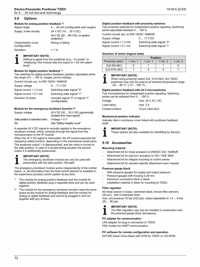
5.9 Options
Module for analog position feedback 1) Signal range 4 ... 20 mA (configurable split ranges) Supply, 2-wire circuitry 24 V DC (10 ... 30 V DC) 48 V DC (20 ... 48 V DC, no ignition
protection) Characteristic curve (configurable)
Rising or falling
Deviation < 1 %
IMPORTANT (NOTE) Without a signal from the positioner (e.g., “no power” or “initializing”) the module sets the output to > 20 mA (alarm level)
Module for digital position feedback 1) Two switches for digital position feedback (position adjustable within the range of 0 ... 100 %, ranges cannot overlap) Current circuits acc. to DIN 19234 / NAMUR Supply voltage 5 ... 11 V DC Signal current < 1.2 mA Switching state logical “0“ Signal current > 2.1 mA Switching state logical “1“ Direction of action normally logical “0“ or logical “1“
(configurable) Module for the emergency shutdown function 2) Supply voltage 24 V DC (20 ... 30 V DC) (galvanically
isolated from input signal) Safe position is activated when Voltage < 5 V SIL See "Safety Integrity Level"
A separate 24 V DC signal is normally applied to the emergency shutdown module, which connects through the signal from the microprocessor to the I/P module. When the 24 V DC signal is interrupted, the I/P module executes the respective safety function, depending on the mechanical construction. The positioner output 1 is depressurized, and the valve is moved to the safe position. In case of a double-acting actuator the second output 2 is additionally pressurized.
IMPORTANT (NOTE) The emergency shutdown module can only be used with pneumatics with the safe position “fail-safe”.
The emergency shutdown module works independently of the mother board, i.e. all information from the final control element is available in the supervisory process control system at any time.
1) The module for analog position feedback and the module for digital position feedback plug in separate slots and can be used together.
2) The module for the emergency shutdown function uses the same space as the module for analog feedback and the module for analog or digital feedback and cannot be plugged in and run together with any of them.
Digital position feedback with proximity switches Two proximity switches for independent position signaling, Switching points adjustable between 0 ... 100 % Current circuits acc. to DIN 19234 / NAMUR Supply voltage 5 ... 11 V DC Signal current < 1.2 mA Switching state logical “0“ Signal current > 2.1 mA Switching state logical “1“ Direction of action (logical state)
Position Proximity switch < Lim. 1 > Lim. 1 < Lim. 2 > Lim. 2
SJ2-SN (NC) 0 1 1 0 SJ2-S1N (NO) 1 0 0 1
IMPORTANT (NOTE) When using proximity switch SJ2_S1N (NO), the TZIDC positioner may only be used at an ambient temperature range -25 ... 85 °C (-13 ... 185 °F).
Digital position feedback with 24 V microswitches Two microswitches for independent position signaling. Switching points can be adjusted from 0 ... 100 %. Voltage max. 24 V AC / DC Load rating max. 2 A Contact surface 10 µm Gold (AU) Mechanical position indicator Indicator disk in enclosure cover linked with positioner feedback shaft.
IMPORTANT (NOTE) These options are also available for retrofitting by Service.
5.10 Accessories
Mounting material - Attachment kit for linear actuators to DIN/IEC 534 / NAMUR - Attachment kit for part-turn actuators to VDI / VDE 3845 - Attachment kit for integral mounting to control valves - Attachment kit for actuator-specific attachment upon request
Pressure gauge block - With pressure gauges for supply and output pressure. - Pressure gauges with housing ø 28 mm - Aluminum connection block in black - Installation material in black for mounting to TZIDC
Filter regulator All metal version in brass, varnished black, bronze filter element, (40 µm) , with condensate drain. max. pre-pressure 16 bar (232 psi), output adjustable to 1.4 ... 6 bar (20 ... 90 psi).
IMPORTANT (NOTE) The filter regulator may only be installed in combination with the pressure gauge block (accessory).
PC adapter for communication LKS adapter for plug-in connection to TZIDC FSK modem for HART communication
PC software for remote configuration and operation DAT200 Asset Vision Basic with DTM for TZIDC on CD-ROM
Change from one to two col umns
Electro-Pneumatic Positioner TZIDC 10/18-0.22-EN for 4 ... 20 mA two-wire technology
13
6 Ex relevant specifications Change from one to two col umns
6.1 ATEX
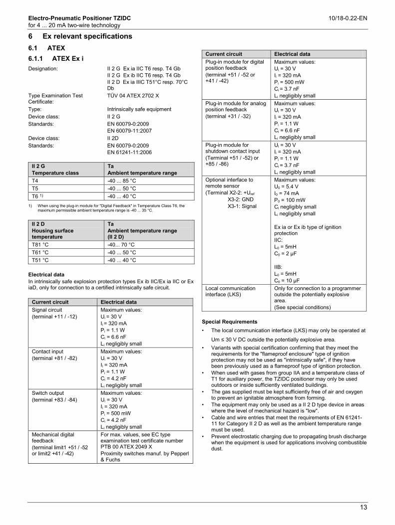
6.1.1 ATEX Ex i
Designation: II 2 G Ex ia IIC T6 resp. T4 Gb II 2 G Ex ib IIC T6 resp. T4 Gb II 2 D Ex ia IIIC T51°C resp. 70°C Db
Type Examination Test Certificate:
TÜV 04 ATEX 2702 X
Type: Intrinsically safe equipment Device class: II 2 G Standards: EN 60079-0:2009
EN 60079-11:2007 Device class: II 2D Standards: EN 60079-0:2009
EN 61241-11:2006
II 2 G Temperature class
Ta Ambient temperature range
T4 -40 ... 85 °C T5 -40 ... 50 °C T6 1) -40 ... 40 °C
1) When using the plug-in module for "Digital Feedback" in Temperature Class T6, the
maximum permissible ambient temperature range is -40 ... 35 °C.
II 2 D Housing surface temperature
Ta Ambient temperature range (II 2 D)
T81 °C -40... 70 °C T61 °C -40 ... 50 °C T51 °C -40 ... 40 °C
Electrical data In intrinsically safe explosion protection types Ex ib IIC/Ex ia IIC or Ex iaD, only for connection to a certified intrinsically safe circuit.
Current circuit Electrical data Signal circuit (terminal +11 / -12)
Maximum values: Ui = 30 V Ii = 320 mA Pi = 1.1 W Ci = 6.6 nF Li negligibly small
Contact input (terminal +81 / -82)
Maximum values: Ui = 30 V Ii = 320 mA Pi = 1.1 W Ci = 4.2 nF Li negligibly small
Switch output (terminal +83 / -84)
Maximum values: Ui = 30 V Ii = 320 mA Pi = 500 mW Ci = 4.2 nF Li negligibly small
Mechanical digital feedback (terminal limit1 +51 / -52 or limit2 +41 / -42)
For max. values, see EC type examination test certificate number PTB 00 ATEX 2049 X Proximity switches manuf. by Pepperl & Fuchs
Current circuit Electrical data Plug-in module for digital position feedback (terminal +51 / -52 or +41 / -42)
Maximum values: Ui = 30 V Ii = 320 mA Pi = 500 mW Ci = 3.7 nF Li negligibly small
Plug-in module for analog position feedback (terminal +31 / -32)
Maximum values: Ui = 30 V Ii = 320 mA Pi = 1.1 W Ci = 6.6 nF Li negligibly small
Plug-in module for shutdown contact input (Terminal +51 / -52) or +85 / -86)
Ui = 30 V Ii = 320 mA Pi = 1.1 W Ci = 3.7 nF Li negligibly small
Optional interface to remote sensor (Terminal X2-2: +Uref X3-2: GND X3-1: Signal
Maximum values: U0 = 5.4 V I0 = 74 mA P0 = 100 mW Ci negligibly small Li negligibly small Ex ia or Ex ib type of ignition protection IIC: L0 = 5mH C0 = 2 µF IIB: L0 = 5mH C0 = 10 µF
Local communication interface (LKS)
Only for connection to a programmer outside the potentially explosive area. (See special conditions)
Special Requirements • The local communication interface (LKS) may only be operated at
Um ≤ 30 V DC outside the potentially explosive area. • Variants with special certification confirming that they meet the
requirements for the "flameproof enclosure" type of ignition protection may not be used as "intrinsically safe", if they have been previously used as a flameproof type of ignition protection.
• When used with gases from group IIA and a temperature class of T1 for auxiliary power, the TZIDC positioner may only be used outdoors or inside sufficiently ventilated buildings.
• The gas supplied must be kept sufficiently free of air and oxygen to prevent an ignitable atmosphere from forming.
• The equipment may only be used as a II 2 D type device in areas where the level of mechanical hazard is "low".
• Cable and wire entries that meet the requirements of EN 61241-11 for Category II 2 D as well as the ambient temperature range must be used.
• Prevent electrostatic charging due to propagating brush discharge when the equipment is used for applications involving combustible dust.

Electro-Pneumatic Positioner TZIDC 10/18-0.22-EN for 4 ... 20 mA two-wire technology
14
6.1.2 ATEX Ex n
Designation: II 3 G Ex nA IIC T6 or T4 Gc Declaration of conformity: TÜV 02 ATEX 1943 X Type: "n" type of protection Device class: II 3 G Standards:
EN 60079-15:2010 EN 60079-0:2009
II 3 G Temperature class
Ta Ambient temperature range
T4 -40 ... 85 °C T6 -40 ... 50 °C
Electrical data
Current circuit Electrical data Signal circuit (terminal +11 / -12)
U = 9.7 V DC I = 4 ... 20 mA, max. 21.5 mA
Contact input (terminal +81 / -82)
U = 12 ... 24 V DC; 4 mA
Switch output (terminal +83 / -84)
U = 11 V DC
Mechanical digital feedback (terminal limit1 +51 / -52 or limit2 +41 / -42)
U = 5 to 11 V DC
Plug-in module for digital position feedback (terminal +51 / -52 or +41 / -42)
U = 5 ... 11 V DC
Plug-in module for analog position feedback (terminal +31 / -32)
U = 10 ... 30 V DC I = 4 ... 20 mA, max. 21.5 mA
Plug-in module for shutdown contact input (Terminal +51 / -52) or +85 / -86)
U = 20 ... 30 V DC
Special Requirements • Devices may only be connected to circuits in zone 2 if they are
suitable for operation in zone 2 potentially explosive atmospheres and for the conditions prevailing at the installation location (manufacturer's declaration or certificate from an inspection authority).
• For the "digital feedback with proximity switches" circuit, external measures must be implemented to prevent the rated voltage from being exceeded by more than 40 % in the event of transient disturbances.
• It is only permissible to connect, disconnect, and switch live circuits during installation or maintenance, or for the purpose of carrying out repairs. Note: It is considered very unlikely that a potentially explosive atmosphere would be present in zone 2 at the same time that installation or maintenance/repair work was being carried out.
• Only non-flammable gases may be used for the pneumatic auxiliary power.
• Only use suitable cable entries which meet the requirements of IEC 60079-15.
• If the SJ2_S1N (NO) proximity switch is used, the positioner may only be operated at an ambient temperature range from -25 ... 85 °C.
6.2 IECEx
Designation: Ex ia IIC T6 or T4 Gb Ex ib IIC T6 or T4 Gb Ex nA IIC T6 or T4 Gc
Certificate No.: IECEx TUN 04.0015X Issue No.: 5 Type: Intrinsic safety "i" or "n" type of
protection Standards: IEC 60079-0:2011
IEC 60079-11:2011 IEC 60079-15:2010
Type and
designation TZIDC Ex ia IIC or Ex ib IIC
Temperature class Ambient temperature range T4 -40 ... 85 °C T4 T6 1) -40 ... 40 °C T6 1)
1) When using the plug-in module for "Digital Feedback" in Temperature Class T6, the
maximum permissible ambient temperature range is -40 ... 35 °C. 6.2.1 IECEx i
Electrical data for a TZIDC designated as Ex ia IIC or Ex ib IIC With the intrinsically safe Ex ib IIC / Ex ia IIC types of ignition protection, only for connection to a certified intrinsically safe circuit.
Electrical data Signal circuit (terminal +11 / -12)
Maximum values: Ui = 30 V li = 320 mA Pi = 1.1 W Ci = 6.6 nF Li negligibly small
Contact input (terminal +81 / -82)
Maximum values: Ui = 30 V li = 320 mA Pi = 1.1 W Ci = 4.2 nF Li negligibly small
Switch output (terminal +83 / -84)
Maximum values: Ui = 30 V li = 320 mA Pi = 500 mW Ci = 4.2 nF Li negligibly small
Local communication interface (LKS)
Only for connection to a programmer outside the potentially explosive area. (See Special conditions)
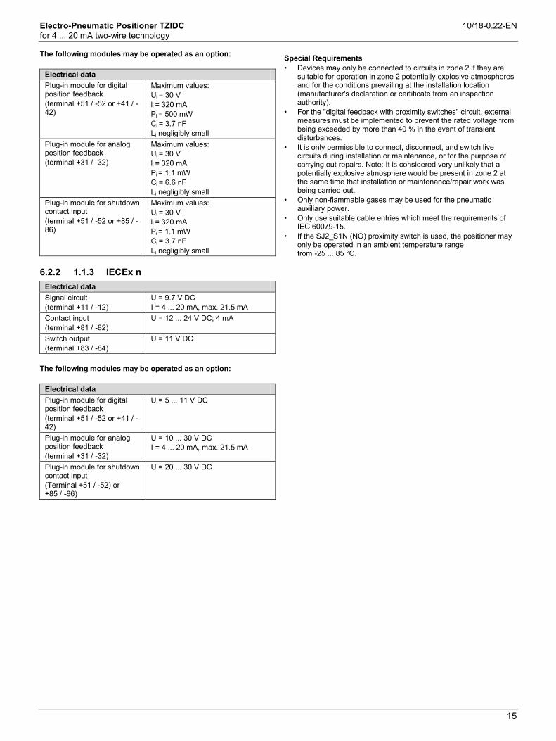
Electro-Pneumatic Positioner TZIDC 10/18-0.22-EN for 4 ... 20 mA two-wire technology
15
The following modules may be operated as an option:
Electrical data Plug-in module for digital position feedback (terminal +51 / -52 or +41 / -42)
Maximum values: Ui = 30 V li = 320 mA Pi = 500 mW Ci = 3.7 nF Li negligibly small
Plug-in module for analog position feedback (terminal +31 / -32)
Maximum values: Ui = 30 V li = 320 mA Pi = 1.1 mW Ci = 6.6 nF Li negligibly small
Plug-in module for shutdown contact input (terminal +51 / -52 or +85 / -86)
Maximum values: Ui = 30 V li = 320 mA Pi = 1.1 mW Ci = 3.7 nF Li negligibly small
6.2.2 1.1.3 IECEx n
Electrical data Signal circuit (terminal +11 / -12)
U = 9.7 V DC I = 4 ... 20 mA, max. 21.5 mA
Contact input (terminal +81 / -82)
U = 12 ... 24 V DC; 4 mA
Switch output (terminal +83 / -84)
U = 11 V DC
The following modules may be operated as an option:
Electrical data Plug-in module for digital position feedback (terminal +51 / -52 or +41 / -42)
U = 5 ... 11 V DC
Plug-in module for analog position feedback (terminal +31 / -32)
U = 10 ... 30 V DC I = 4 ... 20 mA, max. 21.5 mA
Plug-in module for shutdown contact input (Terminal +51 / -52) or +85 / -86)
U = 20 ... 30 V DC
Special Requirements • Devices may only be connected to circuits in zone 2 if they are
suitable for operation in zone 2 potentially explosive atmospheres and for the conditions prevailing at the installation location (manufacturer's declaration or certificate from an inspection authority).
• For the "digital feedback with proximity switches" circuit, external measures must be implemented to prevent the rated voltage from being exceeded by more than 40 % in the event of transient disturbances.
• It is only permissible to connect, disconnect, and switch live circuits during installation or maintenance, or for the purpose of carrying out repairs. Note: It is considered very unlikely that a potentially explosive atmosphere would be present in zone 2 at the same time that installation or maintenance/repair work was being carried out.
• Only non-flammable gases may be used for the pneumatic auxiliary power.
• Only use suitable cable entries which meet the requirements of IEC 60079-15.
• If the SJ2_S1N (NO) proximity switch is used, the positioner may only be operated in an ambient temperature range from -25 ... 85 °C.

Electro-Pneumatic Positioner TZIDC 10/18-0.22-EN for 4 ... 20 mA two-wire technology
16
6.3 FM/CSA 6.3.1 CSA International
Certificate: 1052414 Class 2258 02 PROCESS CONTROL
EQUIPMENT – For Hazardous Locations
Class 2258 04 PROCESS CONTROL EQUIPMENT – Intrinsically Safe, Entity – For Hazardous Locations
Class I, Div 2, Groups A, B, C and D; Class II, Div 2, Groups E, F, and G, Class III, Enclosure Type 4X:
Model TZIDC, P/N V18345-x0x2x2xx0x Intelligent Positioner Input rated 30 V DC; max. 4 ... 20 mA Max output pressure 90 psi Max. ambient 85 Deg C
Class I, Div 1, Groups A, B, C and D; Class II, Div 1, Groups E, F and G Class III, Enclosure Type 4X:
Model TZIDC, P/N V18345-x0x2x2xx0x Intelligent Positioner intrinsically safe with entity parameters of: Terminals 11 / 12 V max = 30 V
I max = 104 mA Ci = 6.6 nF Li = 0 uH
Terminals 81 / 82 V max = 30 V I max = 110 mA Ci = 4.2 nF Li = 0 uH
Terminals 83 / 84 V max = 30 V I max = 90 mA Ci = 4.2 nF Li = 0 uH
Terminals 31 / 32 V max = 30 V I max = 110 mA Ci = 6.6 nF Li = 0 uH
Terminals 41 / 42 and 51 / 52 V max = 30 V I max = 96 mA Ci = 3.7 nF Li = 0 uH
Terminals Limit2 41 / 42 and Limit1 51 / 52
V max = 15.5 V I max = 52 mA Ci = 20 nF Li = 30 uH
When installed per installation Drawing No 901064 Temperature Code Temperature Code Max. Ambient Max. Ambient
IMPORTANT (NOTE) • The "x" in P/N denotes minor mechanical variations or
optional features. • Local communication interface LKS shall not be used in
hazardous location. • Each pair of conductors of each intrinsic safety circuit
shall be shielded..
6.3.2 CSA Certification Record
Certificate: 1649904 (LR 20312) Class 2258 04 PROCESS CONTROL
EQUIPMENT – Intrinsically Safe, Entity – For Hazardous Locations
Class I, Div 1, Groups A, B, C and D; Class II, Div 1, Groups E, F, and G, Class III, Div 1, Enclosure Type 4X:
Model TZIDC, P/N V18345-x0x2x2xx0x Intelligent Positioner Input rated 30 V DC; max.4 ... 20 mA Output pressure Max. 90 psi Intrinsically safe with entity parameters of: Terminals 11 / 12 V max = 30 V
I max = 104 mA Ci = 6.6 nF Li = 0 uH
Terminals 81 / 82 V max = 30 V I max = 110 mA Ci = 3.7 nF Li = 0 uH
Terminals 83 / 84 V max = 30 V I max = 96 mA Ci = 3.7 nF Li = 0 uH
Terminals 31 / 32 V max = 30 V I max = 110 mA Ci = 6.6 nF Li = 0 uH
Terminals 41 / 42 and 51 / 52 V max = 30 V I max = 96 mA Ci = 3.7 nF Li = 0 uH
Terminals Limit2 41 / 42 and Limit1 51 / 52
V max = 15.5 V I max = 52 mA Ci = 20 nF Li = 30 uH
When installed per installation Drawing No 901064 Temperature Code T4 Max. Ambient 85 Deg C
IMPORTANT (NOTE) • The "x" in P/N denotes minor mechanical variations or
optional features. • Local communication interface LKS shall not be used in
hazardous location. • Each pair of conductors of each intrinsic safety circuit
shall be shielded.

Electro-Pneumatic Positioner TZIDC 10/18-0.22-EN for 4 ... 20 mA two-wire technology
17
6.3.3 FM Approvals
TZIDC Positioner, Model V18345-a0b2c2de0f IS/I,II,III/1/ABCDEFG/T4 Ta = 85 °C – 901064/7/4; Enity; NI/I/2/ABCD/T4 Ta = 85 °C; S/II,III/2/FG/T4 Ta =85 °C; Type 4XMax Enity Parameters: Per Control Drawings a = Case/mounting – 1, 2, 3, 4 or 9 b = Input/communication port – 1 or 2 c = Output/safe protection – 1, 2, 4 or 5 d = Option modules for analog or digital position feedback – 0, 1, 3 or 5 e = Mechanical kit (proximity swiches) for digital position feedback (option) – 0, 1 or 3 f = Design (varnish/coding) – 1 or 2
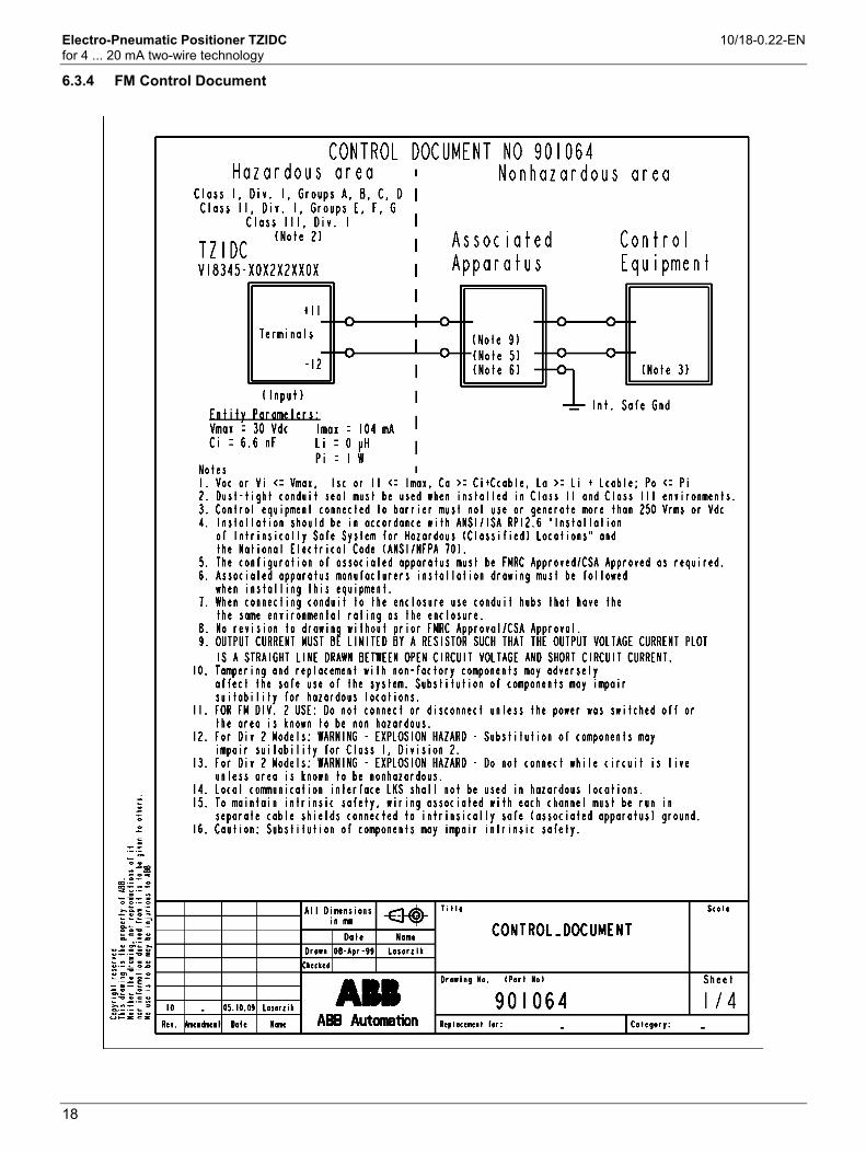
Electro-Pneumatic Positioner TZIDC 10/18-0.22-EN for 4 ... 20 mA two-wire technology
18
Change from one to two col umns
6.3.4 FM Control Document
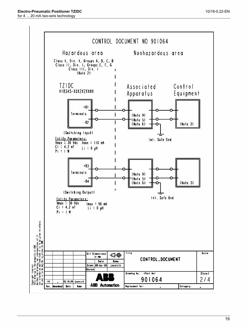
Electro-Pneumatic Positioner TZIDC 10/18-0.22-EN for 4 ... 20 mA two-wire technology
19

Electro-Pneumatic Positioner TZIDC 10/18-0.22-EN for 4 ... 20 mA two-wire technology
20

Electro-Pneumatic Positioner TZIDC 10/18-0.22-EN for 4 ... 20 mA two-wire technology
21

Electro-Pneumatic Positioner TZIDC 10/18-0.22-EN for 4 ... 20 mA two-wire technology
22
7 Electrical connections
Fig. 7: Screw terminals, overview 1 Module for analog position feedback 2 Module for digital feedback or service switch of emergency
shutdown module 3 Module for digital feedback or terminals for emergency
shutdown module 4 Digital position feedback, either proximity switches or 24 V
microswitches
5 Digital position feedback, either proximity switches or 24 V microswitches
6 Digital output DO 7 Digital input 8 Signal 4 ... 20 mA 9 Grounding screw
Fig. 8: Pin configuration A Basic model B Options
1 Analog input 2 Digital input 3 Digital output DO 4 Digital feedback 5 Analog feedback 6 Proximity switches 7 Microswitches 8 Emergency shutdown module
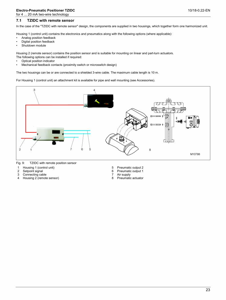
Electro-Pneumatic Positioner TZIDC 10/18-0.22-EN for 4 ... 20 mA two-wire technology
23
7.1 TZIDC with remote sensor
In the case of the "TZIDC with remote sensor" design, the components are supplied in two housings, which together form one harmonized unit. Housing 1 (control unit) contains the electronics and pneumatics along with the following options (where applicable): • Analog position feedback • Digital position feedback • Shutdown module Housing 2 (remote sensor) contains the position sensor and is suitable for mounting on linear and part-turn actuators. The following options can be installed if required: • Optical position indicator • Mechanical feedback contacts (proximity switch or microswitch design) The two housings can be or are connected to a shielded 3-wire cable. The maximum cable length is 10 m. For Housing 1 (control unit) an attachment kit is available for pipe and wall mounting (see Accessories).
Fig. 9: TZIDC with remote position sensor 1 Housing 1 (control unit) 2 Setpoint signal 3 Connecting cable 4 Housing 2 (remote sensor)
5 Pneumatic output 2 6 Pneumatic output 1 7 Air supply 8 Pneumatic actuator

Electro-Pneumatic Positioner TZIDC 10/18-0.22-EN for 4 ... 20 mA two-wire technology
24
7.2 TZIDC for external remote sensor
In the case of the TZIDC design for remote sensor, the positioner is supplied without position detection. The housing (control unit) contains the electronics and pneumatics along with the following options (where applicable): • Analog position feedback • Digital position feedback • Shutdown module The TZIDC designed for the remote sensors can be connected to any position sensor (4 ... 30 kΩ, with open circuit detection 4 ... 18 kΩ). The maximum length of the shielded 3-wire cable is 10 m.
Fig. 10: TZIDC for remote sensors 1 Housing (control unit) 2 Setpoint signal 3 Connecting cable 4 Remote sensor
5 Pneumatic output 2 6 Pneumatic output 1 7 Air supply 8 Pneumatic drive

Electro-Pneumatic Positioner TZIDC 10/18-0.22-EN for 4 ... 20 mA two-wire technology
25
8 Dimensions
All dimensions in mm (inch)
Fig. 11: Top view
Fig. 12: Front and rear views A Tap hole M8 (10 mm low) B Tap hole M6 (8 mm low)
C Tap hole M5 x 0.5 (air vents for direct mount) D Sensor shaft (larger than scale)
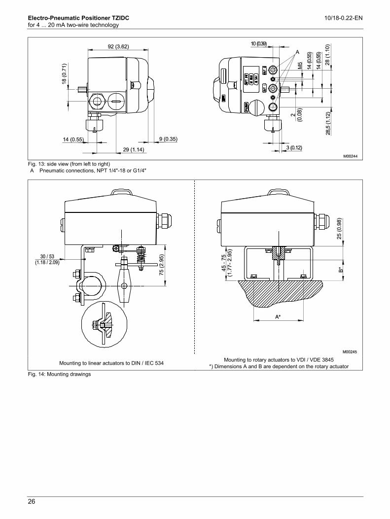
Electro-Pneumatic Positioner TZIDC 10/18-0.22-EN for 4 ... 20 mA two-wire technology
26
Fig. 13: side view (from left to right) A Pneumatic connections, NPT 1/4"-18 or G1/4"
Mounting to linear actuators to DIN / IEC 534 Mounting to rotary actuators to VDI / VDE 3845 *) Dimensions A and B are dependent on the rotary actuator
Fig. 14: Mounting drawings

Electro-Pneumatic Positioner TZIDC 10/18-0.22-EN for 4 ... 20 mA two-wire technology
27
Fig. 15: Positioner TZIDC with pressure gauge block and filter regulator

Contactos/Contacts:
Comercial/Commercial:
Fernando Mena Costa
e-mail: fcosta@bhb,pt
Tel: (+351) 21 843 64 00
Fax: (+351) 21 843 64 09
Assistência/Service:
Patricia Costa
e-mail: [email protected]
Tel: (+351) 21 843 64 00
Note:
ABB the owner of this document, reserves the right to make technical changes or modify the contents of this document without prior notice. With regard to purchase orders, the agreed particulars shall prevail. ABB does not accept any responsibility whatsoever for potential errors or possible lack of information in this document.
Copyright© 2011
ABB. All rights reserved