Edo ppp-coe-cor-int-xxx-014-208-236-rev-a-tml lisco cathodic protection system
23
----- ----- A 30.01.2012 ISSUED FOR INFORMATION O.Y O.Y E.D Rev. No. Date Description Prepared Checked Contr. By Approved ------------ ORIGINATOR Published by EDOPEC ENERJİ PETROL MÜHENDİSLİK SANAYİİ VE TİCARET LİMİTED ŞİRKETİ Contractor Document Title Document Title TML LISCO CATHODİC PROTECTİON SYSTEM Office : Palmiye Mah. Adnan menderes Bulv Oktay Sitesi Document No. menderes Bulv. Oktay Sitesi No: 9/8 PK = 33100 Yenişehir /Mersin –TURKEY P:+90 324 3260595 F:+90 324 3260596 www.edopec.com . [email protected] EDO PPP COE COR INT XXX 014 208 236 Rev A Co. Org. Cod Doc Type Disc. Code Unit Code Prj. type Prj. NO Prıj. Year Pro.Doc. Seq.No DCC Seq.No Page Scale 23
Transcript of Edo ppp-coe-cor-int-xxx-014-208-236-rev-a-tml lisco cathodic protection system
----------
A 30.01.2012 ISSUED FOR INFORMATION O.Y O.Y E.D
Rev.No. Date Description
Prepared Checked Contr. By Approved ------------
ORIGINATOR Published by
EDOPEC ENERJİ PETROL MÜHENDİSLİK SANAYİİ VE TİCARET LİMİTED ŞİRKETİ
Contractor
Document TitleDocument Title
TML LISCO CATHODİC PROTECTİON SYSTEM
Office : Palmiye Mah. Adnanmenderes Bulv Oktay Sitesi
Document No.menderes Bulv. Oktay SitesiNo: 9/8 PK = 33100 Yenişehir /Mersin –TURKEYP:+90 324 3260595 F:+90 324 3260596www.edopec.com. [email protected]
EDO PPP COE COR INT XXX 014 208 236 Rev ACo. Org.
CodDoc Type
Disc. Code
Unit Code
Prj. type
Prj.NO
Prıj.Year
Pro.Doc.Seq.No
DCC Seq.NoPage Scale
23

G.S.P.L.A.J.G.S.P.L.A.J.LIBYAN IRON AND STEEL COMPANYLIBYAN IRON AND STEEL COMPANY
Development of Bulk Berth No:2 and Loading Berth
Cathodic Protection of Steel Piles

C th diC th di P t tiP t ti St d dSt d dCathodic Cathodic ProtectionProtection StandardsStandards::
•• Det Norske Veritas DNV RP B401, January 2005 Recommended Practice Cathodic Det Norske Veritas DNV RP B401, January 2005 Recommended Practice Cathodic P t ti D iP t ti D iProtection Design Protection Design
•• BS EN 13174 Cathodic Protection for Harbour Installations. BS EN 13174 Cathodic Protection for Harbour Installations. •• NORSOK, Standard Common Requirements, Cathodic Protection M503 September NORSOK, Standard Common Requirements, Cathodic Protection M503 September
199719971997 1997 •• NACE International RP 0387NACE International RP 0387--99, Metallurgical and Inspection Requirements for Cast 99, Metallurgical and Inspection Requirements for Cast
Galvanic Anodes Offshore Applications. Galvanic Anodes Offshore Applications. •• BS 7361 Part 1 CP Code of Practice for Land and Marine ApplicationsBS 7361 Part 1 CP Code of Practice for Land and Marine Applications•• BS 7361, Part 1, CP Code of Practice for Land and Marine ApplicationsBS 7361, Part 1, CP Code of Practice for Land and Marine Applications•• BS EN 13509, 2003, CP Measuring Techniques BS EN 13509, 2003, CP Measuring Techniques •• TS 09 Cathodic Protection SystemTS 09 Cathodic Protection System (LISCO)(LISCO)
C th diC th di P t ti M th dP t ti M th dCathodicCathodic Protection MethodProtection Methodss::
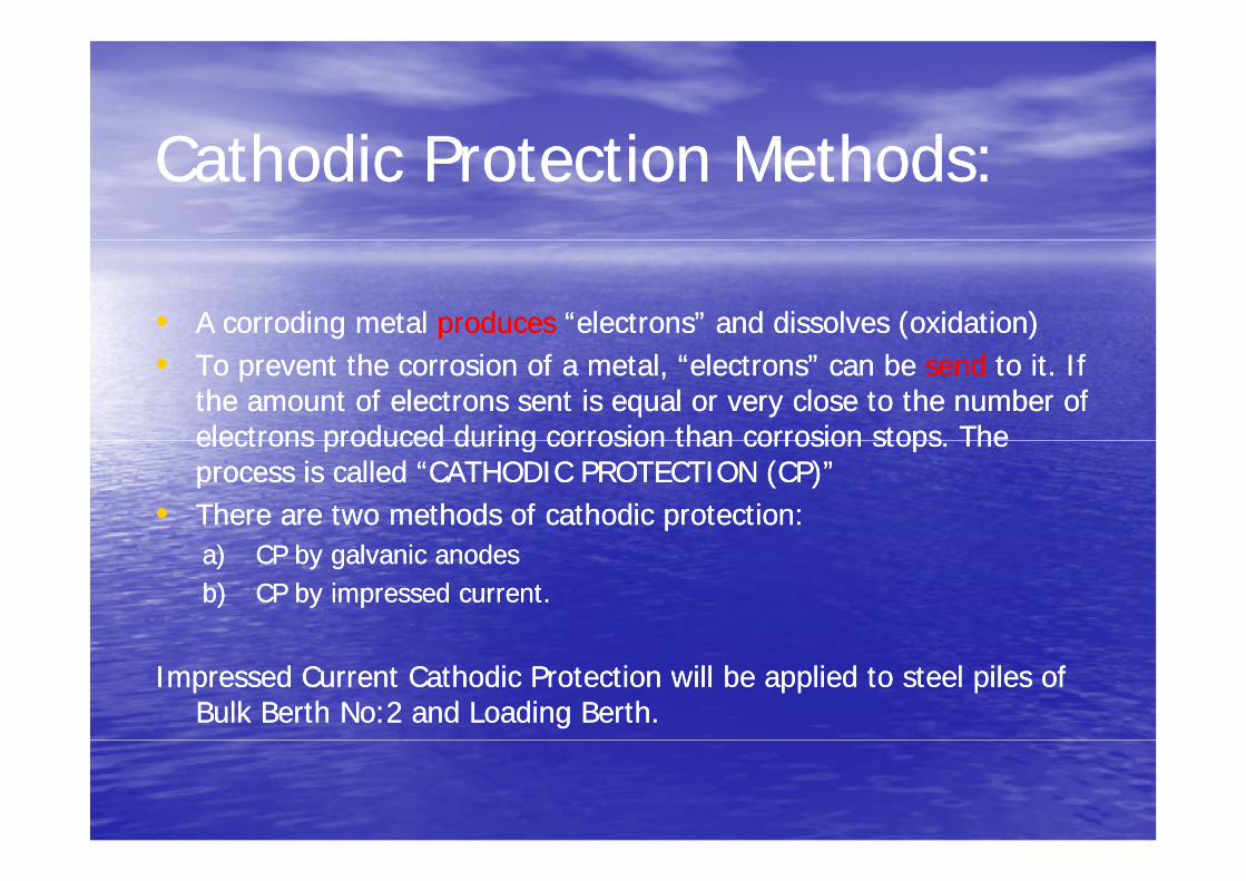
•• A corroding metal A corroding metal producesproduces “electrons” and dissolves (oxidation)“electrons” and dissolves (oxidation)•• To prevent the corrosion of a metal, “electrons” can be To prevent the corrosion of a metal, “electrons” can be sendsend to it. If to it. If
the amount of electrons sent is equal or very close to the number of the amount of electrons sent is equal or very close to the number of electrons produced during corrosion than corrosion stops Theelectrons produced during corrosion than corrosion stops Theelectrons produced during corrosion than corrosion stops. The electrons produced during corrosion than corrosion stops. The process is called “CATHODIC PROTECTION (CP)” process is called “CATHODIC PROTECTION (CP)”
•• There are two methods of cathodic protection:There are two methods of cathodic protection:a)a) CP by galvanic anodesCP by galvanic anodesb)b) CP by impressed current.CP by impressed current.
Impressed Current Cathodic Protection will be applied to steel piles of Impressed Current Cathodic Protection will be applied to steel piles of Bulk Berth No:2 and Loading Berth. Bulk Berth No:2 and Loading Berth.
P i i l f h di i h dP i i l f h di i h dPrinciples of cathodic protection methods:Principles of cathodic protection methods:
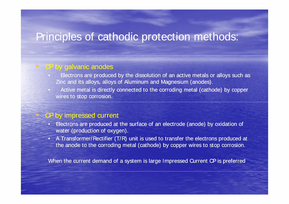
•• CP by galvanic anodesCP by galvanic anodes•• Electrons are produced by the dissolution of an active metals or alloys such as Electrons are produced by the dissolution of an active metals or alloys such as
Zinc and its alloys, alloys of Aluminum and Magnesium (anodes).Zinc and its alloys, alloys of Aluminum and Magnesium (anodes).•• Active metal is directly connected to the corroding metal (cathode) by copper Active metal is directly connected to the corroding metal (cathode) by copper
wires to stop corrosion.wires to stop corrosion.
•• CP by impressed currentCP by impressed current•• Electrons are produced at the surface of an electrode (anode) by oxidation ofElectrons are produced at the surface of an electrode (anode) by oxidation ofElectrons are produced at the surface of an electrode (anode) by oxidation of Electrons are produced at the surface of an electrode (anode) by oxidation of
water (production of oxygen). water (production of oxygen). •• A Transformer/Rectifier (T/R) unit is used to transfer the electrons produced at A Transformer/Rectifier (T/R) unit is used to transfer the electrons produced at
the anode to the corroding metal (cathode) by copper wires to stop corrosion.the anode to the corroding metal (cathode) by copper wires to stop corrosion.
When the current demand of a system is large Impressed Current CP is preferredWhen the current demand of a system is large Impressed Current CP is preferred
C th diC th di P t ti ThP t ti ThCathodicCathodic Protection Theory:Protection Theory:Impressed Current Cathodic ProtectionImpressed Current Cathodic Protection::Impressed Current Cathodic ProtectionImpressed Current Cathodic Protection: :
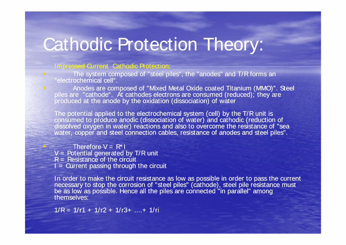
•• The system composed of "steel piles“, the "anodes" and T/R forms an The system composed of "steel piles“, the "anodes" and T/R forms an "electrochemical cell“."electrochemical cell“.
•• Anodes are composed of "Mixed Metal OxideAnodes are composed of "Mixed Metal Oxide coated Titanium (MMO)”. Steel coated Titanium (MMO)”. Steel piles arepiles are "cathode“ At cathodes electrons are consumed"cathode“ At cathodes electrons are consumed (reduced); they are(reduced); they arepiles are piles are cathode . At cathodes electrons are consumedcathode . At cathodes electrons are consumed (reduced); they are (reduced); they are produced at the anode by the oxidationproduced at the anode by the oxidation (dissociation) of water(dissociation) of water
The potential applied to the electrochemical system (cell) by the T/R unit is The potential applied to the electrochemical system (cell) by the T/R unit is consumed to produce anodic (dissociation of water) and cathodic (reduction of consumed to produce anodic (dissociation of water) and cathodic (reduction of p ( ) (p ( ) (dissolved oxygen in water) reactions and alsodissolved oxygen in water) reactions and also to overcome the resistance of "sea to overcome the resistance of "sea water, copper and steel connectionwater, copper and steel connection cables, resistance of anodes and steel piles".cables, resistance of anodes and steel piles".
•• Therefore V = R*ITherefore V = R*Il d b /l d b /V = Potential generated by T/R unitV = Potential generated by T/R unit
R = Resistance of the circuitR = Resistance of the circuitI = Current passing through the circuitI = Current passing through the circuit
In order to make the circuit resistance as low as possible in order to pass the currentIn order to make the circuit resistance as low as possible in order to pass the currentIn order to make the circuit resistance as low as possible in order to pass the current In order to make the circuit resistance as low as possible in order to pass the current necessary to stop the corrosion of "steel piles"necessary to stop the corrosion of "steel piles" (cathode), steel pile resistance must (cathode), steel pile resistance must be as low as possible. Hence allbe as low as possible. Hence all the piles are connected "in parallel" among the piles are connected "in parallel" among themselves:themselves:
1/R = 1/r1 + 1/r2 + 1/r3+ ....+ 1/ri1/R = 1/r1 + 1/r2 + 1/r3+ ....+ 1/ri
C h di P i D i Li PC h di P i D i Li PCathodic Protection Design at Lisco Port:Cathodic Protection Design at Lisco Port:
•• Each Module has its own independent CP system.Each Module has its own independent CP system.
•• There are in total 11 modules on Bulk Berth No:2 and Loading Berth.There are in total 11 modules on Bulk Berth No:2 and Loading Berth.•• Each of these modules are electrically separated from the othersEach of these modules are electrically separated from the others•• Each of these modules are electrically separated from the others. Each of these modules are electrically separated from the others. •• In case of any problem like T/R unit failure, cable connection failure, short circuit In case of any problem like T/R unit failure, cable connection failure, short circuit
or etc, only one module will stay unprotected until the problem has been resolved.or etc, only one module will stay unprotected until the problem has been resolved.•• The design also prevents the leakage currents between anode groups connectedThe design also prevents the leakage currents between anode groups connected•• The design also prevents the leakage currents between anode groups connected The design also prevents the leakage currents between anode groups connected
to different T/R units, caused by different output voltages. The design will to different T/R units, caused by different output voltages. The design will increase the anode life and decreases the electricity consumption.increase the anode life and decreases the electricity consumption.
•• Module design:Module design:E h d l i l t d i t t l t i ll i d d t ti (t h lfE h d l i l t d i t t l t i ll i d d t ti (t h lf•• Each module is also separated into two electrically independent sections (two half Each module is also separated into two electrically independent sections (two half module). Each half module is protected by an independent T/R unit. However module). Each half module is protected by an independent T/R unit. However each T/R unit has a capacity of protecting the whole module (two independent each T/R unit has a capacity of protecting the whole module (two independent half module). But normally it will protect only half of the module.half module). But normally it will protect only half of the module.half module). But normally it will protect only half of the module. half module). But normally it will protect only half of the module.
•• In case of a failure of one of these two T/R units protecting one half module, the In case of a failure of one of these two T/R units protecting one half module, the other T/R unit will be able to protect the whole module temporarily. Thus any of other T/R unit will be able to protect the whole module temporarily. Thus any of the modules will not stay unprotected because of the failure of one T/R Unit. the modules will not stay unprotected because of the failure of one T/R Unit.
•• In the project there are in total 22 T/R units on Bulk Berth No:2 and Loading In the project there are in total 22 T/R units on Bulk Berth No:2 and Loading Berth. However 11 T/R units are enough to protect all modules.Berth. However 11 T/R units are enough to protect all modules.
•• To prevent leakage currents between anode groups connected to different T/R To prevent leakage currents between anode groups connected to different T/R it th d ti it i f d l i di id d i t t t I fit th d ti it i f d l i di id d i t t t I funits, cathode continuity ring of one module is divided into two parts. In case of a units, cathode continuity ring of one module is divided into two parts. In case of a
failure of one T/R unit, these two cathode rings and two anode groups will be able failure of one T/R unit, these two cathode rings and two anode groups will be able to be connected as one cathode ring and one anode group to allow one T/R unit to be connected as one cathode ring and one anode group to allow one T/R unit to protect the whole module manually from inside the anode and cathodeto protect the whole module manually from inside the anode and cathodeto protect the whole module manually from inside the anode and cathode to protect the whole module manually from inside the anode and cathode distribution boxes near the T/R units. distribution boxes near the T/R units.
•• This design will increases the anode life and decrease the electricity consumption.This design will increases the anode life and decrease the electricity consumption.

•• Cathodic Continuity of PilesCathodic Continuity of Piles::
•• All Piles of each half module are interconnected to form a cathodic ring. Each pile All Piles of each half module are interconnected to form a cathodic ring. Each pile is connected to surrounding four piles by galvanized steel ribbons embedded inis connected to surrounding four piles by galvanized steel ribbons embedded inis connected to surrounding four piles by galvanized steel ribbons embedded in is connected to surrounding four piles by galvanized steel ribbons embedded in concrete to prevent their corrosion.concrete to prevent their corrosion.
•• Hence steel piles of each half module form a mesh and connected to cathode Hence steel piles of each half module form a mesh and connected to cathode e ce s ee p es o eac a odu e o a es a d co ec ed o ca odee ce s ee p es o eac a odu e o a es a d co ec ed o ca odedistribution box. In case of a failure of any cathode cable or connection in the distribution box. In case of a failure of any cathode cable or connection in the boxes, current will be able to flow from piles to another cathode connection. In boxes, current will be able to flow from piles to another cathode connection. In case of a failure of continuity rings at some points, current will be able to flow case of a failure of continuity rings at some points, current will be able to flow f il t th d b th th i b f it h d t tf il t th d b th th i b f it h d t tfrom pile to cathode by another way on the ring because of its meshed structure.from pile to cathode by another way on the ring because of its meshed structure.
•• The design will not allow the piles to stay unprotected if any of the continuity bar The design will not allow the piles to stay unprotected if any of the continuity bar is disconnectedis disconnectedis disconnected.is disconnected.

Figure 1: Basic Diagram of Cathodic Protection System (M13)
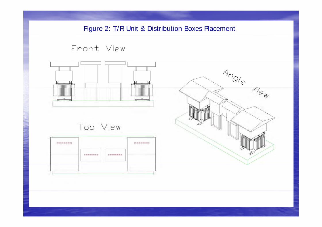
Figure 2: T/R Unit & Distribution Boxes Placement
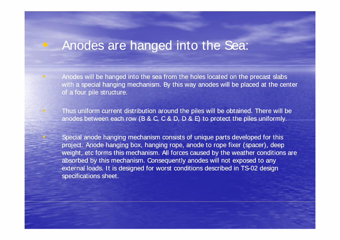
•• Anodes are hanged into the Sea:Anodes are hanged into the Sea:
•• Anodes will be hanged into the sea from the holes located on the precast slabs Anodes will be hanged into the sea from the holes located on the precast slabs with a special hanging mechanism. By this way anodes will be placed at the center with a special hanging mechanism. By this way anodes will be placed at the center of a four pile structureof a four pile structureof a four pile structure. of a four pile structure.
•• Thus uniform current distribution around the piles will be obtained. There will be Thus uniform current distribution around the piles will be obtained. There will be anodes between each row (B & C, C & D, D & E) to protect the piles uniformly.anodes between each row (B & C, C & D, D & E) to protect the piles uniformly.anodes between each row (B & C, C & D, D & E) to protect the piles uniformly. anodes between each row (B & C, C & D, D & E) to protect the piles uniformly.
•• Special anode hanging mechanism consists of unique parts developed for this Special anode hanging mechanism consists of unique parts developed for this project. Anode hanging box, hanging rope, anode to rope fixer (spacer), deep project. Anode hanging box, hanging rope, anode to rope fixer (spacer), deep p j g g , g g p , p ( p ), pp j g g , g g p , p ( p ), pweight, etc forms this mechanism. All forces caused by the weather conditions are weight, etc forms this mechanism. All forces caused by the weather conditions are absorbed by this mechanism. Consequently anodes will not exposed to any absorbed by this mechanism. Consequently anodes will not exposed to any external loads. It is designed for worst conditions described in TSexternal loads. It is designed for worst conditions described in TS--02 design 02 design specifications sheetspecifications sheetspecifications sheet. specifications sheet.
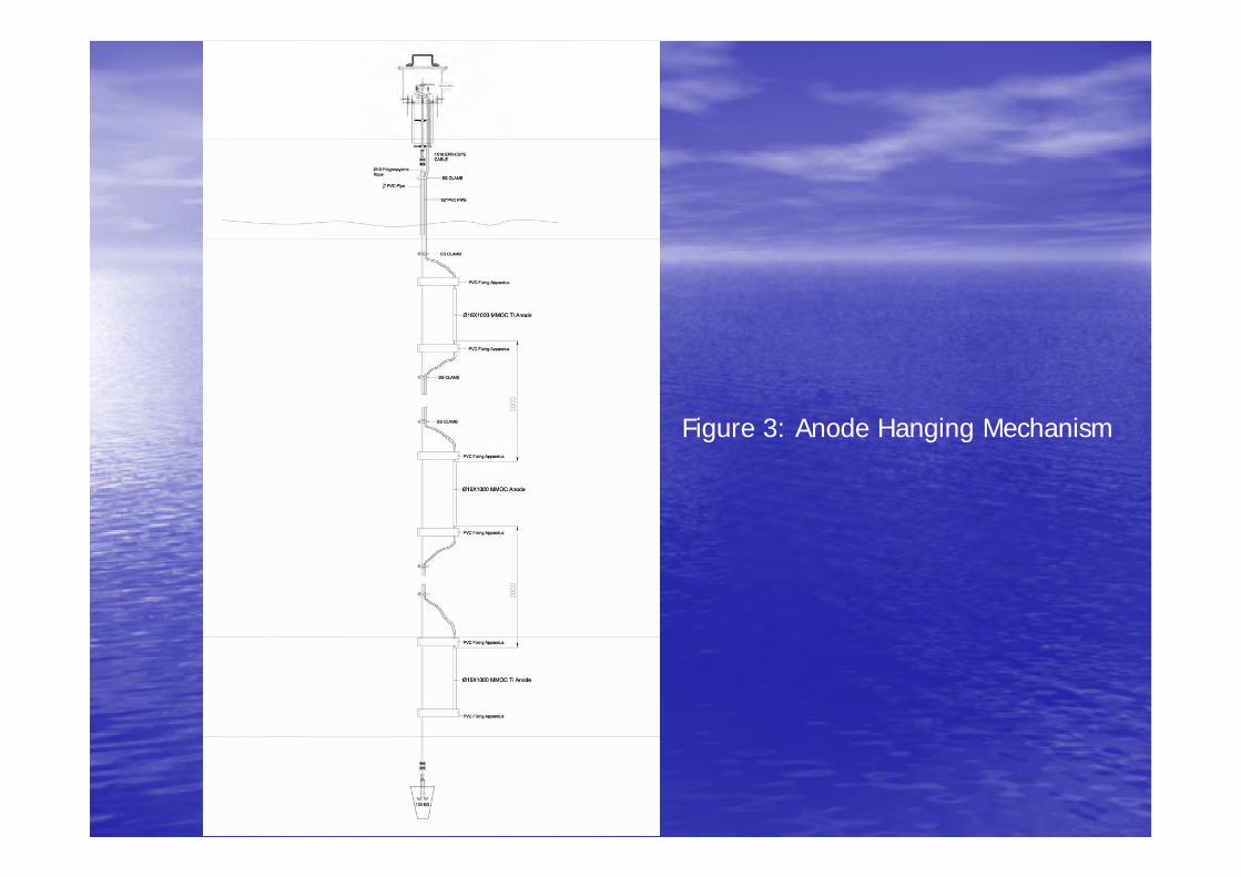
Figure 3: Anode Hanging Mechanismg g g

•• Anode and Cathode Distribution BoxesAnode and Cathode Distribution Boxes::
•• All cables from anode and cathode connection boxes on modules will enter to the All cables from anode and cathode connection boxes on modules will enter to the distribution boxes first. Then they will be connected to T/R units in these boxes.distribution boxes first. Then they will be connected to T/R units in these boxes.
•• In anode distribution box, anode cables will be divided into two parts and each In anode distribution box, anode cables will be divided into two parts and each will be connected to one T/R unit. Connection diagram could be seen on Figure 1. will be connected to one T/R unit. Connection diagram could be seen on Figure 1. There is a compact switch inside the anode distribution box. This is used forThere is a compact switch inside the anode distribution box. This is used forThere is a compact switch inside the anode distribution box. This is used for There is a compact switch inside the anode distribution box. This is used for combining two half module as one group to protect the whole module with one combining two half module as one group to protect the whole module with one T/R unit in case of other’s failure. T/R unit in case of other’s failure.
•• Shunt resistances will be placed into the box for each anode ring and the current Shunt resistances will be placed into the box for each anode ring and the current passing through each circuit will be measured from this box. Also special passing through each circuit will be measured from this box. Also special resistors will be placed for each anode ring to control the current flowing on. resistors will be placed for each anode ring to control the current flowing on.
•• Cathode distribution box has similar design. There is also compact switch inside Cathode distribution box has similar design. There is also compact switch inside the box to allow two half module to receive current from one T/R unit.the box to allow two half module to receive current from one T/R unit.
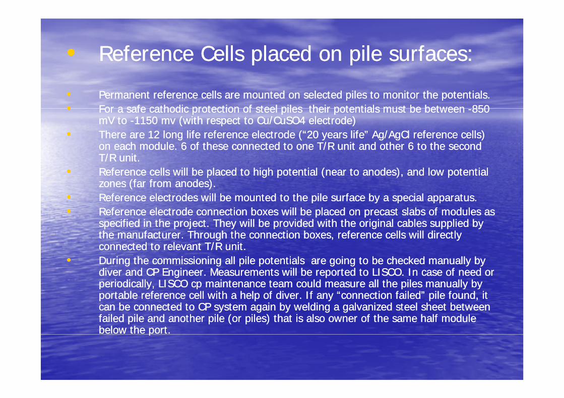
•• Reference Cells placed on pile surfaces:Reference Cells placed on pile surfaces:p pp p
•• Permanent reference cells are mounted on selected piles to monitor the potentials.Permanent reference cells are mounted on selected piles to monitor the potentials.•• For a safe cathodic protection of steel piles their potentials must be betweenFor a safe cathodic protection of steel piles their potentials must be between --850850•• For a safe cathodic protection of steel piles their potentials must be between For a safe cathodic protection of steel piles their potentials must be between --850 850
mV to mV to --1150 mv (with respect to Cu/CuSO4 electrode)1150 mv (with respect to Cu/CuSO4 electrode)•• There are 12 long life reference electrode (“20 years life” Ag/AgCl reference cells) There are 12 long life reference electrode (“20 years life” Ag/AgCl reference cells)
on each module. 6 of these connected to one T/R unit and other 6 to the second on each module. 6 of these connected to one T/R unit and other 6 to the second T/R itT/R itT/R unit. T/R unit.
•• Reference cells will be placed to high potential (near to anodes), and low potential Reference cells will be placed to high potential (near to anodes), and low potential zones (far from anodes). zones (far from anodes).
•• Reference electrodes will be mounted to the pile surface by a special apparatusReference electrodes will be mounted to the pile surface by a special apparatus•• Reference electrodes will be mounted to the pile surface by a special apparatus.Reference electrodes will be mounted to the pile surface by a special apparatus.•• Reference electrode connection boxes will be placed on precast slabs of modules as Reference electrode connection boxes will be placed on precast slabs of modules as
specified in the project. They will be provided with the original cables supplied by specified in the project. They will be provided with the original cables supplied by the manufacturer. Through the connection boxes, reference cells will directly the manufacturer. Through the connection boxes, reference cells will directly connected to relevant T/R unitconnected to relevant T/R unitconnected to relevant T/R unit.connected to relevant T/R unit.
•• During the commissioning all pile potentials are going to be checked manually by During the commissioning all pile potentials are going to be checked manually by diver and CP Engineer. Measurements will be reported to LISCO. In case of need or diver and CP Engineer. Measurements will be reported to LISCO. In case of need or periodically, LISCO cp maintenance team could measure all the piles manually by periodically, LISCO cp maintenance team could measure all the piles manually by p y p p y yp y p p y yportable reference cell with a help of diver. If any “connection failed” pile found, it portable reference cell with a help of diver. If any “connection failed” pile found, it can be connected to CP system again by weldingcan be connected to CP system again by welding aa galvanized steel sheet between galvanized steel sheet between failed pile and another pile (or piles) that is also owner of the same half module failed pile and another pile (or piles) that is also owner of the same half module below the port. below the port. pp
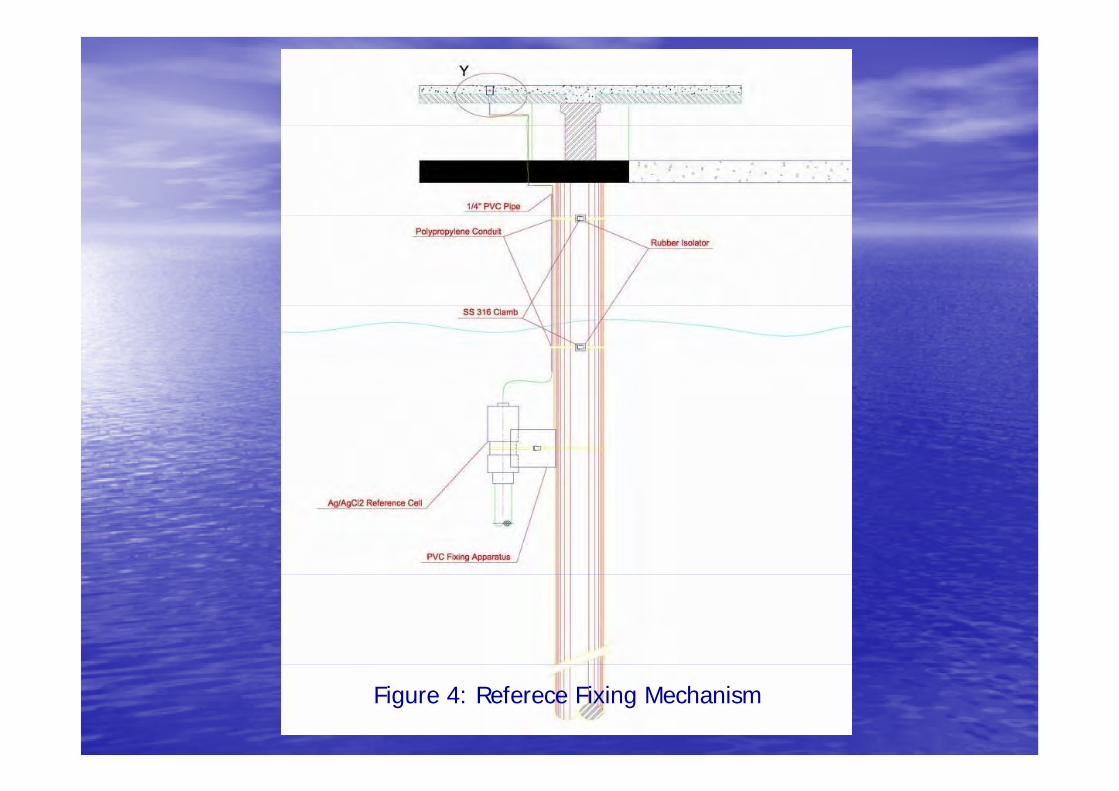
Figure 4: Referece Fixing Mechanism
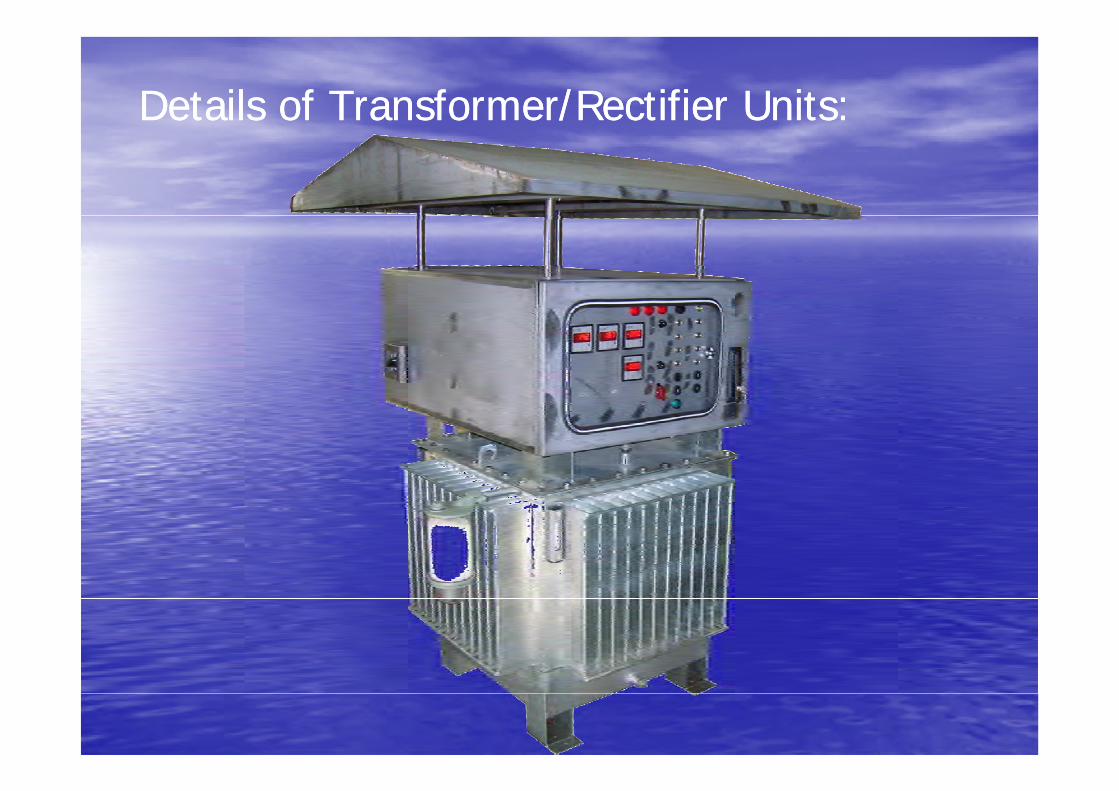
Details of Transformer/Rectifier Units:Details of Transformer/Rectifier Units://
•• General Properties of T/R UnitsGeneral Properties of T/R UnitsGeneral Properties of T/R UnitsGeneral Properties of T/R Units
•• T/R Units will be oil cooled typeT/R Units will be oil cooled type•• T/R Units will be oil cooled type.T/R Units will be oil cooled type.
•• They will consist of two parts. Bottom part will be oil tank. Transformer and heat They will consist of two parts. Bottom part will be oil tank. Transformer and heat generating elements (semiconductors current transformer) will be located insidegenerating elements (semiconductors current transformer) will be located insidegenerating elements (semiconductors, current transformer) will be located inside generating elements (semiconductors, current transformer) will be located inside it. There will be surface expander elements (radiator panels) on the outer surface it. There will be surface expander elements (radiator panels) on the outer surface of the oil tank to increase the heat transfer surface and rate. Silica gel breather of the oil tank to increase the heat transfer surface and rate. Silica gel breather will prevent the humidity to affect the heat transfer oil inside the tank. There will will prevent the humidity to affect the heat transfer oil inside the tank. There will be also analog oil temperature and level indicator on the tank. be also analog oil temperature and level indicator on the tank.
•• Control panel will be mounted on the oil tank. Electronic control cards, Analog to Control panel will be mounted on the oil tank. Electronic control cards, Analog to di it l t f t i it b k li ht i t t i itdi it l t f t i it b k li ht i t t i itdigital converters, fast circuit breakers, lightning arresters, compact circuit digital converters, fast circuit breakers, lightning arresters, compact circuit breakers, cable glands and SCADA equipments will be placed in this panel. The breakers, cable glands and SCADA equipments will be placed in this panel. The front side of the control panel will include user interface consisting of led front side of the control panel will include user interface consisting of led indicators, Digital DC meters and adjustment buttons.indicators, Digital DC meters and adjustment buttons.indicators, Digital DC meters and adjustment buttons.indicators, Digital DC meters and adjustment buttons.
•• Technical Details of Rectifying StackTechnical Details of Rectifying StackTechnical Details of Rectifying StackTechnical Details of Rectifying Stack
•• T/R unit has 3T/R unit has 3--phase toroidal transformer Transformer output enters to rectifyingphase toroidal transformer Transformer output enters to rectifying•• T/R unit has 3T/R unit has 3--phase toroidal transformer. Transformer output enters to rectifying phase toroidal transformer. Transformer output enters to rectifying bridge diodes first. After diodes, there are 200.000 uF input capacitors. They filter bridge diodes first. After diodes, there are 200.000 uF input capacitors. They filter the produced DC voltage by diodes. For driving the DC voltage to cathodic the produced DC voltage by diodes. For driving the DC voltage to cathodic protection system, there is a module IGBT (Isolated Gate Bipolar Transistor) protection system, there is a module IGBT (Isolated Gate Bipolar Transistor) consisting of two IGBTs. PWM (Pulse Width Modulation) signals produced by the consisting of two IGBTs. PWM (Pulse Width Modulation) signals produced by the control card, drives this module IGBT to produce required voltage for the cathodic control card, drives this module IGBT to produce required voltage for the cathodic protection system. protection system.
•• There is also a unique output filter consisting of 2 mH current transformer and There is also a unique output filter consisting of 2 mH current transformer and 200.000 uF output capacitors to reduce the ripples caused by the rectifying 200.000 uF output capacitors to reduce the ripples caused by the rectifying operation below %1 of output voltage These ripples can damage the mixed metaloperation below %1 of output voltage These ripples can damage the mixed metaloperation below %1 of output voltage. These ripples can damage the mixed metal operation below %1 of output voltage. These ripples can damage the mixed metal oxide coating on titanium anodes when they are not filtered well.oxide coating on titanium anodes when they are not filtered well.
•• Technical Details of Control OperationTechnical Details of Control Operation
•• There are 3 different working modes on T/R units. There are 3 different working modes on T/R units. •• First one is “First one is “Continuous AutomaticContinuous Automatic” mode. At this mode, operator can set the ” mode. At this mode, operator can set the
reference electrode voltage that keeps the pile potential constant. T/R unit adjusts reference electrode voltage that keeps the pile potential constant. T/R unit adjusts the rectifying stack by producing proper PWM signals to keep the reference the rectifying stack by producing proper PWM signals to keep the reference electrode set voltage constant on demand. There are 6 reference electrodes electrode set voltage constant on demand. There are 6 reference electrodes connected to each T/R unit Operator can select one of these by step switchconnected to each T/R unit Operator can select one of these by step switchconnected to each T/R unit. Operator can select one of these by step switch connected to each T/R unit. Operator can select one of these by step switch placed on the user panel to be kept constant. placed on the user panel to be kept constant.
•• Second mode is “Second mode is “Continuous ManualContinuous Manual”. Control system keeps the output current ”. Control system keeps the output current constant at a value determined by the operator. In case of reference electrode or constant at a value determined by the operator. In case of reference electrode or y py panalog to digital converter failures, operator can use this mode to protect the analog to digital converter failures, operator can use this mode to protect the system. system.
•• The last mode is “The last mode is “IndependentIndependent” ” mode. At this mode T/R unit acts as adjustable mode. At this mode T/R unit acts as adjustable lt (V i ) O t t th T/R it’ t t ltlt (V i ) O t t th T/R it’ t t ltvoltage source (Variac). Operator can set the T/R unit’s output voltage voltage source (Variac). Operator can set the T/R unit’s output voltage
independent of current or reference electrode potential. independent of current or reference electrode potential.
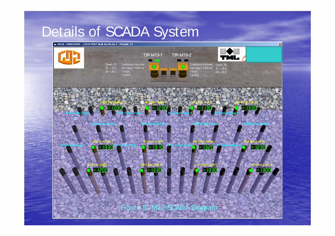
Details of SCADA Systemy
Figure 5: M13 SCADA Diagram
• All T/R units on Bulk Berth No: 2 and Loading Berth will be connected to SCADA system for monitoring cathodic protection system. T/R units will be connected to SCADA t ith i l d t bl ( ith ) D t t i iSCADA computer with special data cables (with spares). Data transmission between T/R units and SCADA monitoring computer will be MODBUS RTU protocol on RS-485 serial communication method.
• There are two MODBUS devices on each T/R Unit One of them transfers the data• There are two MODBUS devices on each T/R Unit. One of them transfers the data on T/R Unit’s control section (Set reference cell value, DC output voltage, CP current, working mode, set value, error codes and temperatures). Second device transfers 6 reference cell readings, DC output voltage and CP current. These two MODBUS devices will also be connected to different data lines. In case of a failure of one of these two MODBUS devices in one T/R unit or one of these two different data lines, system could be monitored continuously by this way.
• A special SCADA software will be developed for monitoring LISCO Port Bulk Berth• A special SCADA software will be developed for monitoring LISCO Port Bulk Berth No:2 and Loading Berth cathodic protection system. There will be a separate windows for each module to watch cathodic protection system in detailed. A Sample view of Module 13 can be seen on Figure 5. There will be one main p gwindow to monitor the whole cathodic protection system. All T/R Unit outputs, reference cell measurements, error codes will be monitored on this screen. The operator will be able to access each module’s detailed window on this screen.

• Each cycle of readings of Bulk Berth No:2 and Loading Berth cathodic protection system will be completed in about 20 seconds (44 MODBUS Devices) All data onsystem will be completed in about 20 seconds (44 MODBUS Devices). All data on the windows will be automatically updated at the and of the cycles.
• SCADA system will record all these measurements and error codes of 11 modules in excel format every minute, daily, monthly and yearly as separate files and y , y, y y y pdirectories, thus the operator will be able to examine the cathodic protection system’s past easily. There will be also a graphical interface to see the changes on CP system easily displaying all selected measurements.SCADA t ill l l t it i LAN (L l A N t k)• SCADA system will also supply remote monitoring on LAN (Local Area Network) or internet. By this way, the operator will be able to control and monitor the cathodic protection system with another computer connected to internet or LAN.


![Tml ppt.[1]](https://static.fdocuments.in/doc/165x107/553804f14a79593a698b46d1/tml-ppt1.jpg)