EDPL 6440 Curriculum Understanding by Design and Sleeter Powerpoint.
Upload
clare-armstrongCategory
view
213download
0
EDMUND FINLEYTRISHA LOWE
NICK MENCHELANNA SLEETER
BOLIVIA BRIDGE:FINAL DESIGN

PROJECT BACKGROUND

DESIGN ALTERNATIVES
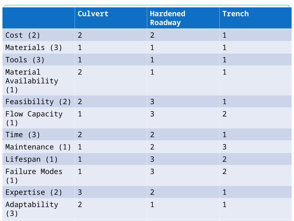
CONSIDERED ALTERNATIVESCulvert Hardened
RoadwayTrench
Cost (2) 2 2 1
Materials (3) 1 1 1
Tools (3) 1 1 1
Material Availability (1)
2 1 1
Feasibility (2) 2 3 1
Flow Capacity (1) 1 3 2
Time (3) 2 2 1
Maintenance (1) 1 2 3
Lifespan (1) 1 3 2
Failure Modes (1)
1 3 2
Expertise (2) 3 2 1
Adaptability (3) 2 1 1
Totals 38 41 29

CONCEPTUAL DESIGN

30%/60% DESIGN

FINAL DESIGN

DESIGN DILEMMAS
Site Inaccurate/inadequate surveying data Lack of flow data (rainfall, size of flood plain) Lack of soil data
Constructability Limited materials Unknown skill sets of laborers Quantity of laborers Time No heavy machinery!

ASSUMPTIONS
Site Cross-section we were asked to build for is near Obrajes 1,
Cross-Section 3 data, so we will use this as an approximation Extrapolated max flow from assuming waterline is at its
highest touching the bank; also considered slope of land from using surveying data of the Obrajes 1 crossing
Assumed the soil had low bearing capacityConstructability
Were able to get a materials list from NGO, Engineers in Action
Assuming unskilled labor Time/manual labor available – can’t do much to change Simple design

TOOLS
To find internal bending moments and shear forces Dr. Gavin’s “three_moment.m” Matlab file for continuous
beams Uses the three moment equation Inputs: spans (between supports), live loads (point loads),
dead loads (distributed loads) Outputs: Max internal bending moments, shear forces,
displacementsTo test design dimensions
Dr. Nadeau’s “Beam Design” excel worksheet, from CE 133 (Concrete Design)
Uses design variables and material properties to determine if, for a given cross-section, a “beam” can carry the internal moment
Also outputs reinforcement specifications

CALCULATIONS
Loading conditions: Live Loads:
Worst case scenario: a 17’ U-Haul sized vehicle, fully loaded, assumed 75% of weight is carried by back tires
Dead Loads: Curb designed for safety Self-weight of the components Weight of parts being supported
Positions: Mid-span and at supports are the worst

CURB DESIGN

SLAB DESIGN

Dead Load
Live Load

SLAB DIMENSIONS
ΦVn ≥ 1.6VL + 1.2VD
VL = 1.74 x 10⁴ N, VD = 1.52 x 10⁻¹ N … d ≥ 6.95 in + at least 1.5 in clear coverh = 22 cm (~8.66 in)Slab is 3.5m across, and 6.2m between piers

BEAM DESIGN

OUTER BEAMS
Dead Load w=wcurb+wslab
Live Load Fvehicle

INNER BEAMS
Dead Load w=wslab
Live Load Fvehicle

BEAM DIMENSIONS
ML = 35.53, MD = 18.5 (outer), 29.23 (inner), kip-ft
From Beam Design worksheet…Outer beam: could be 12 in x 18 inInner beam: needs to be 12 in x 20 inWent with 12 in x 20 inReinforcement: 1 layer, (5) #6 Longitudinal
bars + #3 shear stirrups every ~14.5 in

RETAINING WALL DESIGN
Piers on sides by fill and culverts needed to be designed as retaining walls
Stem thickness set to 12” for constructability purposes
Height: 10.505 ftBase thickness: 0.955 ftBase length: 10 ftHeel length: 6 ftToe length: 3 ft

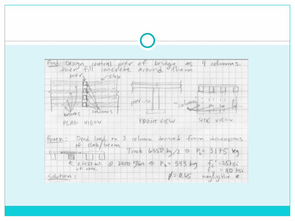
PIER AND FOOTING DESIGN
Designed pier by considering a one foot section as a column
Strip footingWall thickness set at 18”
for constructability purposes
Base length: 1.8 mBase thickness: 0.3 m1 #3 bar/ft


ARMORING
Design a retaining wall to sit in between culverts
Above top of culverts, have a second, unreinforced concrete slab, at an angle
Culvert
Road Bed
FILL
Water flow
Angled slab
Retaining wall

APPROACHES
Not to be greater than 15 degree slopeWill depend on actual site conditions and
therefore will be determined on-site Needs to follow existing roadway
Sloping can begin on area over culverts as long as minimum required soil covering (depending on culvert size) is maintained

OTHER DESIGN CONSIDERATIONS

FLOW CALCULATIONS
Existing railroad bridge is the limiting factorRailroad bridge – two streams;
Our bridge – one stream;Comparable cross-sections = OK!
Assumed water height up to bank, and used this assumption to calculate an existing flow
If our culverts run full we are still OK as cross sectional area is larger than original cross sectional area
Will implement a grading plan, “just in case”

TOPOGRAPHY

SATELLITE IMAGE

RAILROAD BRIDGE

CONSTRUCTION PLAN

MATERIALS/COSTS
Based on volume of concrete of 40 m3 and volume of fill of 300 m3 and assumed 3:2:1 concrete mix ratio (ratio will be determined after speaking with locals who have experience with concrete)
Summarized material list: Portland cement, gravel, sand, culverts, wood for construction, protective gear, nails/fasteners, shovels, wheelbarrows, other tools
Total estimated cost: ~$9500 (US), NOT INCLUDING rebar costs
See design book for cost breakdown

OPERATION & MAINTENANCE
Sign posted that only one vehicle may pass at a time… Could post weight limit as well
Regular inspections should occur every 2 years (during the dry season)
Culverts need to be checked ever 6 months for debris/blockage, and cleared if necessary
Inspections should also be made after especially heavy storms
Maintenance up to community members/Prefectura in Oruro

FINAL DESIGN

QUESTIONS?