EDIZ. 06/05/2014 … CITY2+ electric gates...Value moves the world EDIZ. 06/05/2014 GB CITY2+...
25
Value moves the world www.remotecontrolgates.co.uk EDIZ. 06/05/2014 GB CITY2+ CITY2+L CITY2+ BC DIGITAL CONTROL UNIT (24V) FOR LEAF SWING AND SLIDING GATES
Transcript of EDIZ. 06/05/2014 … CITY2+ electric gates...Value moves the world EDIZ. 06/05/2014 GB CITY2+...

Value moves the worldwww.remotecontrolgates.co.ukEDIZ. 06/05/2014
GB
CITY2+CITY2+LCITY2+ BC
DIGITAL CONTROL UNIT (24V) FOR LEAF SWING AND SLIDING GATES

EN
GLIS
H
- 25 -
INDEX
1 - IMPORTANT REMARKS .........................................................................................................................................
2 - DECLARATION OF CONFORMITY .........................................................................................................................
3 - TECHNICAL SPECIFICATIONS ................................................................................................................................
4 - DESCRIPTION OF THE CONTROL UNIT .................................................................................................................
5 - INSTALLATION .......................................................................................................................................................
5.1 - POWER SUPPLY ...............................................................................................................................................
5.2 - MOTORS .........................................................................................................................................................
5.3 - ACTIVATION INPUTS ........................................................................................................................................
5.4 - STOP ...............................................................................................................................................................
5.5-PHOTOCELLS ..................................................................................................................................................
5.6 - SAFETY RIBBONS ............................................................................................................................................
5.7-LOWVOLTAGELIGHT(24V) ............................................................................................................................
5.8-230VCOURTESYLIGHTORFLASHINGLIGHT ..................................................................................................
5.9 - LOCK ..............................................................................................................................................................
5.10-LIMITSWITCHANDENCODER ......................................................................................................................
5.11 - EXTERNAL AERIAL .........................................................................................................................................
5.12 - PLUG IN RECEIVER ........................................................................................................................................
5.13 - ADI INTERFACE .............................................................................................................................................
5.14 - ELECTRIC CONNECTIONS ..............................................................................................................................
6 - CONTROL PANEL ...................................................................................................................................................
6.1-USEOFTHEDOWN,MENUANDUPKEYSFORPROGRAMMING .....................................................................
7 - QUICK CONFIGURATION .......................................................................................................................................
8 - LOADING OF DEFAULT PARAMETERS ..................................................................................................................
9 - SELF-LEARNING OF WORKING TIMES ..................................................................................................................
10 - READING OF CYCLE COUNTER ...........................................................................................................................
10.1 - SIGNALOFSERVICEREQUIRED .....................................................................................................................
11 - CONTROL UNIT CONFIGURATION ......................................................................................................................
12 - OPERATION DEFECTS ..........................................................................................................................................
26
26
26
27
27
27
27
28
28
28
29
29
29
29
30
31
31
31
32
34
34
35
35
36
37
37
38
46

www.remotecontrolgates.co.uk
- 26 -
1 - IMPORTANT REMARKS
ForanyinstallationproblempleasecontactourCustomerServiceatthenumber+39-0172.812411operatingMondaytoFridayfrom8:30to12:30andfrom14:00to18:00.
V2 has the right to modify the product without previous notice; it also declines any responsibility to damage or injury to people or things caused by improper use or wrong installation.
m Please read this instruction manual very carefully before installing and programming your control unit.
• Thisinstructionmanualisonlyforqualifiedtechnicians,whospecialize in installations and automations.
• Thecontentsofthisinstructionmanualdonotconcerntheenduser.
• Everyprogrammingand/oreverymaintenanceserviceshouldbedoneonlybyqualifiedtechnicians.
AUTOMATION MUST BE IMPLEMENTED IN COMPLIANCE WITH THE EUROPEAN REGULATIONS IN FORCE:
EN 60204-1 (Machinerysafety.electricalequipmentof machines,part1:generalrules)EN 12445 (Safeuseofautomatedlockingdevices, test methods)EN 12453 (Safeuseofautomatedlockingdevices, requirements)
• Theinstallermustprovideforadevice(es.magnetotermicalswitch)ensuringtheomnipolarsectioningoftheequipmentfromthepowersupply.Thestandardsrequireaseparationofthecontactsofatleast3mmineachpole(EN60335-1).
• Aftermakingconnectionsontheterminalboard,useonehoseclamptofixdangerousvoltagewiresneartheterminalboardandanotherhoseclamptofixsafetylowvoltagewiresusedforaccessoriesconnection;thisway,incaseofaccidentaldetachmentofaconductingwire,dangerousvoltagepartswillnotcomeintocontactwithsafetylowvoltageones.
• TheplasticcasehasanIP55insulation;toconnectflexibleorrigidpipes,usepipefittingshavingthesameinsulationlevel.
• Installationrequiresmechanicalandelectricalskills,thereforeitshallbecarriedoutbyqualifiedpersonnelonly,whocanissuetheComplianceCertificateconcerningthewholeinstallation(EEC Machine Directive 89/392, Annex IIA).
• Theautomatedvehiculargatesshallcomplywiththefollowingrules:EN12453,EN12445,EN12978aswellasanylocalruleinforce.
• Alsotheautomationupstreamelectricsystemshallcomplywiththelawsandrulesinforceandbecarriedoutworkmanlike.
• Thedoorthrustforceadjustmentshallbemeasuredbymeansofapropertoolandadjustedaccordingtothemax.limits,which EN 12453 allows.
• Werecommendtomakeuseofanemergencybutton,tobeinstalledbytheautomation(connectedtothecontrolunitSTOPinput)sothatthegatemaybeimmediatelystoppedincaseofdanger.
• Alwaysremembertoconnecttheearthaccordingtocurrentstandards (EN 60335-1, EN 60204-1).
2 - DECLARATION OF CONFORMITY
V2S.p.A.herebydeclarethatCITY2+productsconformtotheessentialrequirementsestablishedinthefollowingdirectives:
• 2004/108/CEE(EMCDirectiveinaccordancewithstandards EN 55014-1, EN 55014-2, EN 61000-3-2, 61000-3-3)
• 2006/95/CEE(LowVoltageDirectiveinaccordancewithstandards EN 60335-1 + EN 60335-2-103)
• 99/05/CEE(RadioDirectiveinaccordancewithstandard EN 301 489-3)
• DirectiveRoHS22011/65/CE
Racconigi,12/01/2010V2S.p.A.legalrepresentative.Cosimo De Falco
3 - TECHNICAL SPECIFICATIONS
CITY2+ CITY2+L CITY2+BC
Powersupply 230V/50Hz 230V/50Hz 24Vdc
Max total load 250W 200W 250W
Maxloadforeachmotor
150W 100W 150W
Dutyclcle 40% 40% 40%
Max accessories load 24Vdc
7W 7W 7W
Protectionfuse 2,5A 2,5A -
Weight 3000g 1000g 1000g
Dimensions 295 x 230 x 100 mm
Workingtemperature
-20 ÷ +60°C
Protection IP55

EN
GLIS
H
- 27 -
4 - DESCRIPTION OF THE CONTROL UNIT
ThedigitalcontrolunitCITY2+isaninnovativeV2productthatguaranteesasafeandreliableautomationofleafswingorslidinggates.
CITY2+isprovidedwithadisplaythat,notonlymakesprogrammingsimple,butalsoallowsacontinuousmonitoringofthe input statuses; in addition, thanks to a menu structure, the workingscheduleandtheoperationlogiccanbeseteasily.
IncompliancewiththeEuropeanstandardsconcerningelectricalsafetyandelectromagneticcompatibility(EN60335-1,EN 50081-1 and EN 50082-1) it has been equipped with the low voltagecircuittotalelectricinsulation(motorsincluded)fromthenetworkvoltage.
Other characteristics:
• Powersupplyprotectedfromshortcircuitswithinthecontroller,on the motors and on the connected accessories
• Adjustmentofthepowerbypartializingthecurrent
• Detectingobstaclesbymonitoringthecurrentonthemotors(currentsensingprobe)
• Automaticlearningoftheoperationtime.
• Testsforsafetydevices(photocells,safetyribbonsandmosfet)beforeeachopening.
• Deactivationofsafetyinputsthroughtheconfigurationmenu:nojumperisrequiredforterminalsconcerningsafetydevicesthathavenotbeeninstalled,yet. Youwillonlyneedtodisablethisfunctionfromitsrelevantmenu.
• Thedevicecanoperatewithoutmainspower,byusingtheoptionalbatterypack(code161212).
• Lowvoltageoutputthatcanbeusedforasignallightora 24Vflashinglight.
• Auxiliaryrelaywithprogrammablelogicforcourtesylight,flashinglightorotheruse.
• ENERGYSAVINGFUNCTION
5 - INSTALLATION
Installationofcontrolunitandsafetydevicesmustbecarriedoutwith power disconnected.
5.1 - POWER SUPPLY
Models CITY2+ / CITY2+L Thecontrolunitmustbefedbya230V50Hz(120V-50/60Hzforthe120Vmodels)electricline,protectedbyadifferentialmagnetothermalswitchcomplyingwiththelawprovisionsinforce.
Connect phase and neutral to terminals L and Noftheboardlocatednexttothetransformer.
CITY2+Connect the earth cable ofthesystemtothepresetfastonAConnect the earth cable ofthemotortothepresetfastonB
CITY2+LConnectthegroundcableofthesystemandofmotorstofastonA
Model CITY2+BC Connect the +poleoftheECOLOGICbatteryboxtotheBAT+ terminalonthecontrolunit(useafastonfortheconnection)Connect the -poleoftheECOLOGICbatteryboxtotheBAT- terminalonthecontrolunit(useafastonfortheconnection)
5.2 - MOTORS
CITY2+ control unit can control one or two 24V motors. Ifthecontrolunitneedstocontrolonemotoronly,thelattermustbeconnectedtoterminalsofmotor1.
Connectmotor1cablesasfollows:
• openingcabletoterminalZ3
• closingcabletoterminalZ4
Connectmotor2(ifany)cablesasfollows:
• openingcabletoterminalZ5
• closingcabletoterminalZ6
m PLEASE NOTE: to avoid interference between the motor and the photocells, it is essential to connect both the motor casing and the control unit frame to the electrical system ground.
F1
MAINS
L NAB
LN
A
F1
www.remotecontrolgates.co.uk
- 28 -
5.4 - STOP
Forabettersafety,youcanfitastopswitchthatwillcausetheimmediategatestopwhenactivated.Thisswitchmusthaveanormallyclosecontactthatwillgetopenincaseofoperation.Incasethestopswitchisoperatedwhilethegateisopen,theautomaticclosingfunctionwillalwaysbedisabled.Toclosethegateagain,youwillneedastartcommand(ifthestartfunctioninpauseisdisabled,itwillbetemporarilyenabledtoallowthegaterelease).
Connect the stop switch cables between terminal L5 (STOP) and L6 (COM)ofthecontrolunit.
Thestopswitchfunctioncanbeactivatedbymeansofaremotecontrolstoredonchannel3(seerelevantinstructionsofMRreceiver). ThecommandSTOPfromremoteisoperativealsoiftheinputSTOPoftheterminalboardisdisabled.
5.5 - PHOTOCELLS
Thecontrolunitconsiderstwokindsofphotocells,dependingontheterminaltowhichtheyareconnected:
Photocell 1Photocellsinstalledonthegateinnerside,whichareactivebothduringtheopeningandtheclosingphase.Whenphotocells1operate,thecontrolunitstopsthegate;assoonasthephotocellbeamisfree,thecontrolunitwillopenthegatecompletely.
m WARNING: Type 1 photocells must be installed so that they completely cover the opening area of the gate.
Photocell 2Photocellsinstalledontheexternalgatesideandwhichareactiveduringtheclosingphaseonly.Whenphotocells2operate,thecontrolunitopensthegateimmediately,withoutwaitingforrelease.
CITY2+controlunitsuppliesa24Vdcpowersupplytophotocellsanditcanperformaphotocelloperationtestbeforestartingthegateopeningphase.Photocellpowerterminalsareprotectedbyanelectronicfusethatstopscurrentincaseofoverload.
m PLEASE NOTE: it is recommended that the cable ducts used for the motor cables NOT BE USED for the cables connecting the photocells.
• Connectpowersupplycablesofphotocellstransmitterbetween terminals K7 (-) and K8 (+Test) ofthecontrolunit.
• Connectpowersupplycablesofphotocellsreceiverbetweenterminals K6 (+) and K7 (-)ofthecontrolunit.
• Connectreceiveroutputofphotocells1betweenterminals L7 (PHOTO1) and L11 (COM)ofthecontrolunitandreceiveroutputofphotocells2betweenterminalsL8 (PHOTO2) and L11 (COM)ofthecontrolunit. Useoutputshavingnormallyclosedcontact.
m WARNING:
• ifseveralcouplesofsamekindphotocellsaremounted,theiroutputs must be connected in series.
• Incaseofreflectionphotocells,powersupplymustbeconnected to terminals K7 (-) and K8 (+Test)ofthecontrolunittocarryouttheoperationtest.
5.3 - ACTIVATION INPUTS
CITY2+ control unit is equipped with two activation inputs(START and START P.), whose operation depends on the programmedoperationmodes(seeStrtitemofprogrammingmenu)
Standard modeSTART = START (a command will cause the completeopeningofthegate)START P. = PEDESTRIAN START (a command will cause thepartialopeningofthegate)
Open/Close commandSTART=OPENING(alwayscontrolsthegateopening)STARTP.=CLOSING(alwayscontrolsthegateclosing)Thisisanimpulsecommand,thatistosaythatanimpulsewillcausethecompletegateopeningorclosing.
Dead man operationSTART=OPENING(alwayscontrolsthegateopening)STARTP.=CLOSING(alwayscontrolsthegateclosing)Thisisamonostablecommand,thatistosay,thegatewillbeopenedorclosedaslongasthecontactisclosedanditwillimmediatelystopasthecontactisopen
Timer modeThisfunctionallowsprogrammingthegateopeningtimeduringtheday,bymakinguseofanexternaltimer.
START=START(acommandwillcausethecompleteopeningofthegate)START P. = PEDESTRIAN START (a command will cause the partial openingofthegate)
Thegatestaysopen(completelyorpartially)whilethecontactisclosed on input; as soon as the contact is open the pause time countdownwillstart,afterwhichthegatewillbeclosedagain.
m ATTENTION: Automatic closing must be enabled.
NOTE: in all modes, inputs must be connected to devices having normally open contacts.
Connectcablesofdevicecontrollingthefirstinputbetweenterminals L3 (START) and L6 (COM)ofthecontrolunit.Connectcablesofdevicecontrollingthesecondinputbetweenterminals L4 (START P.) and L6 (COM)ofthecontrolunit.
ThefirstinputfunctioncanalsobeactivatedbypressingUPkeyoutsidetheprogrammingmenuorbymeansofaremotecontrolstoredonchannel1(seerelevantinstructionsofMRreceiver).
ThesecondinputfunctioncanalsobeactivatedbypressingDOWNkeyoutsidetheprogrammingmenuorbymeansofaremote control stored on channel 2.

EN
GLIS
H
- 29 -
5.7 - LOW VOLTAGE LIGHT (24V)
The CITY2+ controller has a 24 V DC output that allows connections to a load up to 15 W.Thisoutputcanbeusedtoconnectasignallightthatindicatesthatstatusofthegate,orforalowvoltageflashinglight.
Connectthelowvoltagesignallightorflashinglightwirestoterminals Z1 (+) and Z2 (-).
m CAUTION: Pay attention to the polarity of the connected device if necessary.
5.8 - 230V COURTESY LIGHT OR FLASHING LIGHT
ThankstotheoutputCOURTESYLIGHTthecontrolunitallowstheconnectionofanelectricappliance(e.g.courtesylightorgardenlights),controlledautomaticallyorbymeansofthespecialtransmitterkey.
Thecourtesylightterminalscanbealternativelyusedfora230Vflashinglightwithintegratedflasher.CAUTION: When the controller is operating on battery power, the 230 V flashing light will not work.
TheoutputCOURTESYLIGHTisasimpleN.O.contactwithnopowersupply(themaximumratingoftherelayis5A-230V).
Connect the cables to terminals B1 and B2.
5.9 - LOCK
Anelectriclockcanbeassembledonthegate,toensureagoodclosingofdoors.Makeuseofa12Vlock.
Connect lock cables to terminals K9 and K10 ofthecontrolunit.
5.6 - SAFETY RIBBONS
Thecontrolunitconsiderstwokindsofsafetyribbons,dependingontheterminaltowhichtheyareconnected:
Type 1 (fixed)Theyaremountedonwallsoronotherfixedobstaclesthatareapproachedbythegatedoorsduringtheopeningphase. Whentype1safetyribbonsoperateduringthegateopeningphase,thecontrolunitwillclosethedoorsfor3seconds,thenitstandsstill;whentype1safetyribbonsoperateduringthegateclosingphase,thecontrolunitwillstandstillimmediately.ThedirectionofthegateatnextcommandofSTARTorPEDESTRIAN START depends upon the parameter STOP (it inverts or continues the motion). IftheinputSTOPisdisabled,thecommandmakesthemotioncontinueinthesamedirection.IftheSTOPinputisdisabled,thecontrolrestartsmotioninthesamedirectionitwastravellingpriortotheinterventionoftheedge.
Type 2 (mobile)Theyaremountedtothedoorends.Whentype2safetyribbonsoperateduringthegateopeningphase,thecontrolunitwillstandstillimmediately;whentype2safetyribbonsoperateduringthegateclosing,thecontrolunitwillopenthedoorsfor3seconds,thenitwillstandstill.ThedirectionofthegateatnextcommandofSTARTorPEDESTRIAN START depends upon the parameter STOP (it inverts orcontinuesthemotion).IftheinputSTOPisdisabled,thecommand makes the motion continue in the same direction. IftheSTOPinputisdisabled,thecontrolrestartsmotioninthesamedirectionitwastravellingpriortotheinterventionoftheedge.
Boththeinputcanmanagetheclassicsafetyedgewithn.c.contactandtheconductiverubbersafetyedgewith8,2kohmnominal resistance.
Connecttype1safetyribbonscablesbetweenterminalsL9 (EDGE1) and L11 (COM)ofthecontrolunit.Connecttype2safetyribbonscablesbetweenterminalsL10 (EDGE2) and L11 (COM)ofthecontrolunit.
InordertomeettherequirementsoftheEN12978rules,itisnecessarytoinstallsafetyedgescontrolledbyacontrolunitcontinuouslycheckingtheproperworking.Ifusingcontrolunitssuitedtothetestbypoweroutage,connectthepowersupplycablesofthecontrolunitbetweenterminalsK7 (-) and K8 (+Test) ofthecontrolunit.Otherwise, connect them between terminals K6 (+) and K7 (-).
m WARNING:
• Makeuseofsafetyribbonshavingoutputswithnormallyclosecontact.
• Outputsofsamekindsafetyribbonsmustbeconnectedinseries.

www.remotecontrolgates.co.uk
- 30 -
5.10 - LIMIT SWITCH AND ENCODER
TheCITY2+controllercancontrolthegate’stravelusingalimitswitch and/or an encoder.
m CAUTION: The use of these devices is strongly recommended to ensure that the gate opens and closes correctly.
ThespeedofoperationoftheDCmotorscanbeconditionedbyvariationsinmainspower,atmosphericconditions,andfrictionofthegate.Furthermore,encodersalsoallowthecontrollertodetermineifthegatestopsinanirregularpositionduetoanobstacle.
Forencoderoperation,itisrequiredthattheclosurepositionforeachsectionofthegatebedetectableusingalimitswitchsensoror a mechanical stop. Eachtimethecontrolleristurnedon,torealigntheencoders,thegateiscloseduntilitreachesthelimitswitchorthemechanicalstop.
Thecontrolunitsupportstwokindsofendofstroke:
• endofstrokeequippedwithanormallycloseswitchthatwillbe opened as soon as the door reaches its position desired (set the parameter FC.En = L.SW)
• endofstrokeinseriesofmotorwinding(settheparameterFC.En = Cor.0)
GATES WITH TWO PANELSForgateswithtwopanels,limitswitchesandencoderssharethesameterminalssoitisnotpossibletoinstallbothofthesedevicesat the same time.
m PLEASE NOTE: refer to the motor manual
Installationoflimitswitch
• Connecttheopenlimitswitchtomotor1usingterminals K1 (FCA1) and K5 (COM)
• Connectthecloselimitswitchtomotor1usingterminals K2 (FCC1) and K5 (COM)
• Connecttheopenlimitswitchtomotor2usingterminals K3 (FCA2) and K5 (COM)
• Connectthecloselimitswitchtomotor2usingterminals K4 (FCC2) and K5 (COM)
Installationofencoders
• Connectthepowersourceforbothencoderstoterminals K5 (COM) and K6 (+)
• Connecttheencoderoutputstomotor1usingterminals K3 (FCA2) and K4 (FCC2)
• Connecttheencoderoutputstomotor2usingterminals K1 (FCA1) and K2 (FCC1)
m Check that the two pairs of wires have been correctly connected and after installation proceed as follows:
1. Disable encoder operation (Enco menu)
2. Setameaningfulopendelay(r.AP menu)
NOTE: The default settings in the controller satisfy points 1 and 2.
3. Give a START command:
- Ifbothgatepanelsmove,thewiresareconnectedcorrectly
- IfErr7appearsonthedisplayoncepanel1startstomove,invert the wires connected to terminals K3 (FCA2) and K4 (FCC2)
- IfErr7 appearsonthedisplayoncepanel2startstomove,invert the wires connected to terminals K1 (FCA1) and K2 (FCC1)
GATES WITH SINGLE PANELSInstallationoflimitswitch
• ConnecttheopenlimitswitchtoterminalsK1 (FCA1) and K5 (COM)
• ConnectthecloselimitswitchtoterminalsK2 (FCC1) and K5 (COM)
Installationofencoder
• Connectthepowersourcefortheencodertoterminals K5 (COM) and K6 (+)
• Connecttheencoderoutputtoterminals K3 (FCA2) and K4 (FCC2)
Checkthatthetwoencoderwireshavebeencorrectlyconnectedandafterinstallationproceedasfollows:
1. Disable encoder operation (Enco menu)
2. Give a START command:
- Ifthegatemoves,thewiresareconnectedcorrectly
- IfErr7appearsonthedisplayoncethegatestartstomove, invert the wires connected to terminals K3 (FCA2) and K4 (FCC2)

EN
GLIS
H
- 31 -
5.11 - EXTERNAL AERIAL
Wesuggesttousetheexternalaerial(model:ANS433)inordertoguaranteethemaximalrange.
Connect the antenna hot pole to terminal L1 (ANT)ofthecontrolunitandthebraidingtoterminalL2 (ANT-).
5.12 - PLUG IN RECEIVER
CITY2+controlunitissuitableforplugginginaMRreceiver.
m WARNING: Pay attention to the way you connect the removable modules.
MRmodulereceiverisprovidedwith4channelsandeachofthemissuitableforacommandofCITY2+controlunit:• CHANNEL1 g START• CHANNEL2 g PEDESTRIAN START • CHANNEL3 g STOP• CHANNEL4 gCOURTESYLIGHT
m WARNING: Before programming 4 channels and function logics read carefully the instructions of MR.
5.13 - ADI INTERFACE
TheADI(AdditionalDevicesInterface)interfaceofthecontrolunitCITY2+ allows the connection to V2 optional modules.
RefertoV2catalogueortothetechnicalsheetstoseewhichoptionalmoduleswithADIinterfaceareavailableforthiscontrolunit.
m WARNING: Please read the instructions of each single module to install the optional modules.
Forsomedevices,itispossibletoconfigurethemodeforinterfacingwiththecontrolunit;inaddition,itisnecessarytoenabletheinterfacesothatthecontrolunitcanprocessthesignalsarrivingfromtheADIdevice.
Pleaserefertothei.AdiprogrammingmenutoenabletheADIinterfaceandaccessthedeviceconfigurationmenu.
TheADIdevicecansignalphotocell,edgeorstopalarms:
• Photocell alarms -thegatestopsmoving,whenthealarmstopsopeningrestarts.
• Edge alarm -invertsmotionofthegatefor3seconds.
• Stop alarm-thegatestopsandcannotrestartuntilthealarmstops.

www.remotecontrolgates.co.uk
- 32 -
AN
T
STA
RT
STO
P
STA
RT
P.
CO
M
PHO
TO1
PHO
TO2
EDG
E1
EDG
E2
CO
M
FCA
1
FCC
1
FCA
2
FCC
2
CO
M
+24
VD
C
CO
M (
-)
+24
VD
C (
TEST
)
LOC
K
LIG
HT
24V
M1 M2
CO
UR
TESY
LI
GH
T C
ON
TAC
T
AN
T-
L1 L2 L3 L4 L5 L6 L7 L8 L9 L10L11 K1 K2 K3 K4 K5 K6 K7 K8 K9 K10 Z1 Z2 Z3 Z4 Z5 Z6 B1 B2
L1 Antenna
L2 Antenna shield
L3 Openingcontrolfortheconnectionofcontroldevices with N.O. contact
L4 OpeningcontrolsforpedestrianaccessfortheconnectionofcontroldeviceswithN.O.contact
L5 Stop command. N.C. contact
L6 Common (-)
L7 Photocellstype1.N.C.contact
L8 Photocellstype2.N.C.contact
L9 Safetyribbonstype1(fixed).N.C.contact
L10 Safetyribbonstype2(mobile).N.C.contact
L11 Common (-)
Z1 - Z2 Lowvoltagelight(24V)
Z3 Motor 1 (OPENING)
Z4 Motor 1 (CLOSING)
Z5 Motor 2 (OPENING)
Z6 Motor 2 (CLOSING)
B1 - B2 230VACcourtesylightorflashinglight
POW+ +24Vpowersupply
POW- Powersupply(-)
BAT+ +poleoftheoptionalbatterypack(code161212)ortheECO-LOGICbatterybox
BAT- -poleoftheoptionalbatterypack(code161212)ortheECO-LOGICbatterybox
L Power phase 230 VAC
N Neutral 230 VAC
RECEIVER Pluginreceiver
ADI ADIinterface
OVERLOAD It shows that there is an overload on accessories powersupply
MAINS It shows that the control unit is power supplied
F1 2,5A
K1 Open limit switch motor 1 Encoder motor 2K2 Close limit switch motor 1
K3 Open limit switch motor 2 Encoder motor 1K4 Close limit switch motor 2
K5 Common (-)
K6 Poweroutput+24Vdcforphotocellsandotheraccessories
K7 Commonforaccessoriespowersupply
K8 Photocell/opticaledgeTXpowersupplyforfunctionaltest
K9 - K10 LOCK 12V
5.14 - ELECTRIC CONNECTIONS

EN
GLIS
H
- 33 -
F1
L N
LN
F1
MAINS
MAINS
CITY2+
CITY2+L
CITY2+CITY2+L
CITY2+BC
OVERLOAD
DOWN MENU UP
BAT-POW+
POW-
BA
T+
REC
EIV
ER

www.remotecontrolgates.co.uk
- 34 -
6 - CONTROL PANEL
Whenpowerison,thecontrolunitchecksthatdisplaycorrectlyoperatesbyswitchingonallsegmentsfor1.5sec.8.8.8.8. Firmwareversion,e.g.Pr 2.4,willbeviewedinthefollowing1.5 sec.
Panelwillbevieweduponcompletionofthistest.
Thecontrolpanelrepresentsthephysicalstatusoftheterminalboardcontactsandoftheprogrammodekeys:iftheupperverticalsegmentison,thecontactisclosed;ifthelowerverticalsegmentison,thecontactisopen(theabovepictureshowsaninstancewheretheinputsLIMITSWITCH,PHOTOCELL1,PHOTOCELL2,SAFETYRIBBONS1,SAFETYRIBBONS2andSTOPhaveallbeencorrectlyconnected).
The segments indicated as REMOTE SAFETY show the status oftheremotesafetydevicesforthedeviceconnectedtotheADIconnector.
• IftheADIinterfaceisnotenabled(nodeviceconnected),bothsegmentsremainturnedoff.
• Ifthedeviceindicatesaphotocellalarm,theuppersegmentcomes on.
• Ifthedeviceindicatesanedgealarm,thelowersegmentcomeson.
• Ifthedeviceindicatesastopalarm,bothsegmentsstartflashing.
Points being among display digits showthestatusofprogrammingpush-buttons:assoonasapush-buttonispressed,its relevant point turns on.
The arrows on the left of the display showthestateofthestartinputs.Thearrowslightwhentherelatedinputisclosed.
The arrows on the display right side showthegatestatus:
• Thehighestarrowturnsonwhenthegateisintoitsopeningphase.Ifitblinks,itmeansthattheopeninghasbeencausedbyasafetydevice(borderorobstacledetector).
• Thecentralarrowshowsthatthegateisonpause. Ifitblinks,itmeansthatthetimecountdownfortheautomaticclosinghasbeenactivated.
• Thelowestarrowblinkswhenthegateisintoitsclosingphase.Ifitblinks,itmeansthattheclosinghasbeencausedbyasafetydevice(borderorobstacledetector).
6.1 - USE OF THE DOWN, MENU AND UP KEYS FOR PROGRAMMING
Programmingofthefunctionsandtimesofthecontrollerisperformedusingaspecialconfigurationmenuthatisaccessedandexploredusing3keys,DOWN,MENU,andUP,whicharelocatedbelowthedisplay.
m CAUTION: Except in the configuration menu, pressing the UP key activates a START command and pressing the DOWN key activates a START PEDESTRIAN command.
Toactivatetheprogrammingmodes(thedisplaymustshowthecontrolpanel),pressandholddowntheMENUkeyuntil-PrG appearsonthedisplay.
HolddowntheMENUkeytoscrollthroughthe4mainmenus:-PrG CONTROLLER PROGRAMMING-Cnt COUNTERS-APP SELF-LEARNING OF WORKING TIMES-dEF LOAD DEFAULT PARAMETERS
Toenteroneofthefourmainmenus,justreleasetheMENUkeywhenthemenuyouwantappearsonthedisplay.
Tomovethroughthefourmainmenus,presstheUPandDOWNkeystoscrollthroughthevariousitems.PresstheMENUkeytodisplaythecurrentvalueoftheselecteditemandchangeitifneeded.
OPENING IN PROGRESS
OPEN CONTACTCLOSED CONTACT
START
PEDESTRIANSTART
PAUSE (GATE OPENED)CLOSING IN PROGRESS
STOPPHOTOCELL 1
DOWNPHOTOCELL 2
SAFETY RIBBON 1MENU
LIMIT SWITCH (MOTOR 2)ENCODER (MOTOR 1)LIMIT SWITCH (MOTOR 1)ENCODER (MOTOR 2)UPREMOTE SAFETYSAFETY RIBBON 2
MENU
3”
3”
3”
3”
MENU
6”
MENU
9”
MENU
12”
KEY PRESSED
KEY RELEASED

EN
GLIS
H
- 35 -
7 - QUICK CONFIGURATION
Thisparagraphconcernsaquickproceduretosetthecontrolunitandsetitatworkimmediately.
Werecommendfollowingtheseinstructions,inordertocheckquicklythecorrectoperationofcontrolunit,motorandaccessories,andthenchangingtheconfigurationincaseofanynon-satisfactoryparameter.
1. Callupthedefaultconfiguration(chapter8)
m CAUTION: If there is only one motor, set the open time, t.AP2, to zero in order to inform the controller that the parameters for motor 2 do not need to be considered.
2. Set items StoP - Fot1 - Fot2 - CoS1 - CoS2 accordingtothesafetydevicesinstalledonthegate.
3. Starttheself-learningcycle(chapter11)
4. checkthattheautomationworkproperlyandifnecessarymodifytheconfigurationofthedesiredparameters.
8 - LOADING OF DEFAULT PARAMETERS
Ifnecessary,itispossibletorestorealltheparameterstotheirstandardordefaultvalue(seetableattheend)
m WARNING: This procedure causes the loss of all the customized parameters, therefore it has been put outside the configuration menu, to reduce the possibility of executing it by mistake.
1. PressandholddowntheMENUkeyuntilthe-dEF appears onthedisplay
2. ReleasetheMENUkey:thedisplaywillshowESC (press the MENUkeyonlyifyouwanttoleavethismenu)
3. PresstheDOWNkey:dEF willappearonthedisplay.
4. PresstheMENUkey:nowillappearonthedisplay.
5. PresstheDOWNkey:Siwillappearonthedisplay.
6. PresstheMENUkey:Alloftheparametersarereturnedtotheirdefaultvalues(seethetableonpages37)andthedisplayshows the control panel
www.remotecontrolgates.co.uk
- 36 -
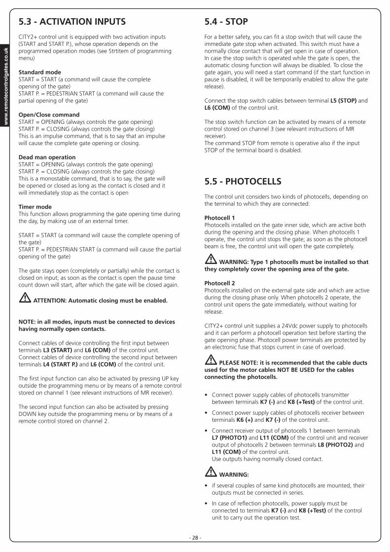
9 - SELF-LEARNING OF WORKING TIMES
Thismenuallowstheautomaticlearningofthetimesnecessarytoopenandclosethegate.Duringthisphase,thecontrolunitmemorizesalsotheforcesnecessarytoopenandclosethegate:thesevalueswillbeactivatedbyusingtheobstaclesensor.Theencoderpositionsarealsosaved,ifenabled.
m CAUTION: Before continuing, make certain that the limit switch(es) and encoder(s) have been installed correctly. Limit switches and encoders, if installed, must be enabled using the specific menu.
1. PressandholddowntheMENUkeyuntilthe-APP appears onthedisplay
2. ReleasetheMENUkey:thedisplaywillshowESC (press the MENUkeyonlyifyouwanttoleavethismenu)
3. PresstheDOWNkey:t.LAvwillappearonthedisplay.
4. PresstheMENUkeytostarttheself-learningcyclefortheworkcycletimes:
CAUTION:Thisprocedurevariesbasedonthenumberofgatepanels and travel control devices installed. Ifthereisnolimitswitchorencoderinstalled,onlypoints4.4and4.5areperformed.Ifthereisonlyonemotor(t.AP2 = 0), the procedurestartsfrompoint4.3
4.1 Gatepanel1isopenedforafewseconds
4.2 Gatepanel2iscloseduntiloneofthefollowingconditionsoccurs:
- it reaches the limit switch
- The obstacle sensor or the encoder detect that the gatepanelisjammed
- ASTARTcommandisgiven
Thispositionismemorizedastheclosepointforgatepanel2.
4.3 Gatepanel1iscloseduntiloneoftheconditionslistedin point 4.2 occur: this position is memorized as the close pointforgatepanel1.
4.4 Eachgatepanelisopened.Theoperationendswhenonceoftheconditionsindicatedinpoint4.2occur(thefirstSTARTstopsgatepanel1,thesecondSTARTstopsgatepanel 2). The time required is memorized as the open time.
4.5 Eachgatepanelisclosed.Theoperationendswhenoneoftheconditionsindicatedinpoint4.2occursorwhentheclosed position is reached. The time required is memorized as the close time.
5. Thedisplayshowsthevaluerecommendedfortheobstaclesensorofmotor1.Ifnooperationsareperformedfor20seconds,thecontrollerexitstheprogrammingphasewithoutsavingtherecommendedvalue.
6. TherecommendedvaluecanbechangedusingtheUPandDOWNkeys.PresstheMENUkeytoconfirmthevaluedisplayedandthedisplaywillshowSEn1
7. PresstheDOWNkey:ThedisplaywillshowSEn2. Press the MENUkeytodisplaytherecommendedvaluefortheobstaclesensorformotor2,whichcanbechangedinasimilarmannerasthatforSEn1.
8. HolddowntheDOWNkeyuntiltheFinE appears on the display,thenpresstheMENUkey,selectSi and press the MENUkeytoexitprogrammingandsavethevaluesforthesensors.
m CAUTION: If the controller exits programming due to time out (1 minute), the obstacle sensors return to the values that were set prior to performing self-learning (according to the default values, the sensors are disabled).The open/close times and the encoder positions are always saved.

EN
GLIS
H
- 37 -
10 - READING OF CYCLE COUNTER
CITY2+controlunitcountsthecompletedopeningcyclesofthegateand,ifrequested,itshowsthatserviceisrequiredafterafixednumberofcycles.
There are two counters available:
• Atotalizingcounterforcompletedopeningcyclesthatcannotbe zeroed (option “tot”ofitem“Cont”)
• Adownwardcounterforthenumberofcyclesbeforethenextrequestforservice(option“SErv”ofitem“Cont”). This countercanbeprogrammedaccordingtothedesiredvalue.
Theschemehereaftershowshowtoreadthetotalizingcounter,howtoreadthenumberofcyclesbeforethenextserviceisrequiredaswellashowtoprogramthenumberofcyclesbeforethenextrequestforservice(asfortheexampleshown,thecontrolunitcompletedno.12451cyclesandthereareno.1300cyclesbeforethenextservicerequest.
Area 1isthereadingofthetotalnumberofcompletedcycles;throughUpandDownkeys,youcanalternatethedisplayofthousands or units.
Area 2isthereadingofthenumberofcyclesbeforethenextrequestforservice:itsvalueisroundeddowntothehundreds.
Area 3isthesetupofthislattercounter;ifyoupressonceUPorDOWNkey,thecurrentcountervaluewillberoundedupordowntothousands,anyfollowingpressurewillhavethesetupbeincreasedordecreasedof1000units.Thepreviousdisplayedcountwillgetlost.
10.1 - SIGNAL OF SERVICE REQUIRED Assoonasthecounterofcyclesbeforethenextrequestforserviceiszero,thecontrolunitshowstherequestforservicethroughanadditional5-secondpre-blinking.
Thissignalwillberepeatedateachopeningcycle,untiltheinstallerentersintothecounterreadingandsetupmenu,andpossiblyprogramsthenumberofcyclesafterwhichthenextservice will be requested.
Incasenonewvalueissetup(thatistosaythatthecountervalueisleftatzero),thesignallingfunctionfortheservicerequestwillbedisabledandnosignalwillberepeatedanymore.
m WARNING: service operations shall be carried out by qualified staff only.
3
1
2
www.remotecontrolgates.co.uk
- 38 -
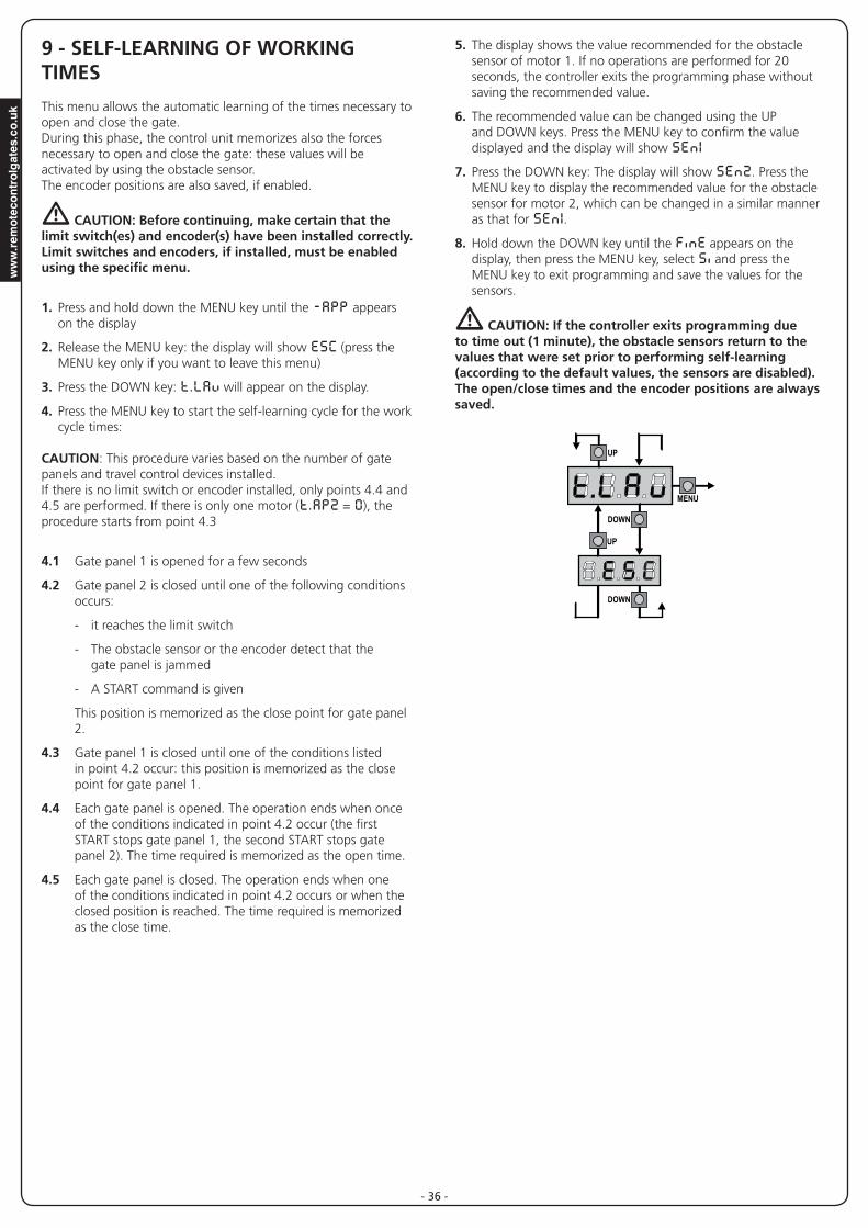
11 - CONTROL UNIT CONFIGURATION
Controlunittimeandfunctionprogrammingismadewithinaspecialconfigurationmenu,towhichyoucanaccessandwhereyoucanshiftthroughDOWN,MENUandUPkeysplacedunderthedisplay.
HolddowntheMENUkeyuntil-PrGappearsondisplay,toactivatetheprogrammingmodewhiledisplayviewsthepanel.
Theconfigurationmenuconsistsinalistofconfigurableitems;thedisplayshowstheselecteditem.
• BypressingDOWN,youwillpasstothenextitem
• BypressingUP,youwillreturntothepreviousitem
• BypressingMENU,youcanviewthecurrentvalueofselecteditemandpossiblychangeit.
The last menu item (FinE)allowsstoringthecarriedoutchangesandgoingbacktothecontrolunitnormaloperation.Youmustexitfromprogrammingmodethroughthismenuitemifyoudonotwanttoloseyourconfiguration.
m WARNING: in case no operation is carried out for more than one minute, the control unit exits from the programming mode without saving any of your setups and changes, which will get lost.
NOTE: ByholdingdowntheUPorDOWNkeys,configurationmenuitemswillscrollfast,untilitemFinEisviewed.Inthisway,youcanquicklyreacheitherthetoporbottomofthelist.
F1
L N
LN
F1
MAINS
MAINS
CITY2+
CITY2+L
CITY2+CITY2+L
CITY2+BC
OVERLOAD
DOWN MENU UP
BAT-POW+
POW-
BA
T+
REC
EIV
ER

EN
GLIS
H
- 39 -
PARAMETER VALUE DESCRIPTION DEFAULT MEMO
En.SA ENERGY SAVING functionThisfunctionisusefulforreducingtheenergyconsumptionoftheautomationdevicewhileinstand-bymode.
Ifthefunctionisenabled,thecontrolunitwillenterENERGYSAVINGmodeunderthefollowingconditions:
• 30secondsaftercompletionofanoperationalcycle
• 30secondsafteranopening(ifautomaticclosureisnotenabled)
• 30secondsafterexitingtheprogrammingmenu
InENERGYSAVINGmode,powertotheaccessories,display,flashinglightsandclosureelectromagnetsisdeactivated.
ENERGY SAVING mode is exited:
• Ifanoperationalcycleisactivated
• Ifoneofthekeysonthecontrolunitarepressed
NOTE: during battery powered operation, if the level of charge is insufficient to activate the automation device (the display shows Err0), the ENERGY SAVING function is activated automatically in order to reduce power consumption while awaiting mains power to be restored.
no
no Function deactivated
Si Function activated
t.AP1 Leaf 1 opening time 22.5”0.0”-5’00 Adjustabletimefrom0secondsto5minutes
t.AP2 Leaf 2 opening time 22.5”0.0”-5’00 Adjustabletimefrom0secondsto5minutes.
WARNING: if motor 2 is not connected, this time must be set to zero
t.APP Partial opening time (pedestrian access) 6.0”0.0”-1’00 When the control unit receives a Start Pedestrian command, it will open
leaf1only,forashortertime.Maxallowedtimetobesetupist.AP1
t.Ch1 Leaf 1 closing time 23.5”0.0”-5’00 Temporegolabileda0secondia5minuti
NOTA:Perevitarechel’antanonsichiudacompletamente,èconsigliabileimpostareuntempopiùlungodiquellodiaperturat.AP1
t.Ch2 Tempo di chiusura anta 2 23.5”0.0”-5’00 Adjustabletimefrom0secondsto5minutes.
NOTE:Toavoidthatthedoordoesnotclosecompletely,werecommendtosetupalongertimethant.AP2openingtime.
t.ChP Partial closing time (pedestrian access) 7.0”0.0” - 2’00 When the control unit receives a Start Pedestrian command, it will use this
timetoclosethegate.Maxallowedtimetobesetupist.Ch1.NOTE:Toavoidthatthedoordoesnotclosecompletely,werecommendtosetupalongertimethant.APPopeningtime
t.C2P Leaf 2 closing time during pedestrian cycle no0.5” - 5.0” Duringapartialopeningcycle(pedestrianaccess)leaf2maymoveslightly
becauseofthewindoritsownweight;inthiscaseatclosingtimeleaf1couldhitleaf2andthegatewouldremainnotperfectlyclosed.Toavoidthis,inthelastsecondsofthecyclealightclosingforceisappliedtoleaf2too.
no Function deactivated

www.remotecontrolgates.co.uk
- 40 -
PARAMETER VALUE DESCRIPTION DEFAULT MEMO
r.AP Opening door delay 1.0”0.0” - 1’00 Duringtheopeningphase,leaf1muststartmovingbeforeleaf2,toavoid
thatbothdoorsmaycollide.Leaf2openingwillbedelayedforthesetuptime
r.Ch Closing door delay 3.0”0.0” - 1’00 Duringtheclosingphase,leaf1muststartmovingafterleaf2,toavoid
thatbothdoorsmaycollide.Leaf1closingwillbedelayedforthesetuptime
t.SEr Lock time 2.0”0.5”- 1’00 Beforetheopeningphasebegins,thecontrolunitwillenergizetheelectric
lockinordertoreleaseitandenablethegatemotion.t.SEr time will fix theenergizingtime.
m WARNING: in case the gate has no electric lock, set the value no
no Function deactivated
SEr.S Silent Locking Mode SiSi Function activated
no Function deactivated
t.ASE Lock advance time 1.0”0.0”- 1’00 Whiletheelectriclockisenergized,thegatewillstaystandstillfort.ASE
time, to make its release easier.In case t.ASE is lower than t.SEr,thelockenergizingwillgoonwhilethedoorswillstartmoving.
mWARNING:incasethegatehasnoelectriclock,setthevalue0.0”
t.inv Backlash time no0.5” - 1’00 Itcouldbeusefultogiveaclosingcommandtomotors,tohelpthe
electric lock release. The control unit controls the motors in reduced power inclosingdirectionforthesetuptime
no Function deactivated
t.PrE Pre-blinking time 1.0”0.5” - 1’00 Beforeanygatemovement,blinkerwillbeactivatedfort.PrE time, to
warnabouttheincomingmotion
no Function deactivated
Pot1 Motor 1 power 10030 - 100 Thedisplayedvalueisthepercentageofmax.motorpower
Pot2 Motor 2 power 10030 - 100 Thedisplayedvalueisthepercentageofmax.motorpower
Po.r1 Power motor 1 during slow-down phase 500 - 70 Thedisplayedvalueisthepercentageofmax.motorpower
Po.r2 Power motor 2 during slow-down phase 500 - 70 Thedisplayedvalueisthepercentageofmax.motorpower

EN
GLIS
H
- 41 -
PARAMETER VALUE DESCRIPTION DEFAULT MEMO
P.bAt Maximum motor power during battery operationDuringbatteryoperation,thecontrollerispoweredwithalowervoltagecomparedtomainspower.Forthisreason,thepowerofthemotorsisreducedcomparedtonormaloperationandmaynotbesufficienttomovethegatepanelseffectively.Thismenuallowsyoutoactivatethemotorsattheirmaximumpowerduringbatteryoperation.
Si
Si Function activated
no Function deactivated
SPUn Start off Whenthegateisstandstillanditbeginsmoving,theinitialinertiamustbefaced,therefore,ifyourgateisquiteheavy,itsdoorscouldnotmove.In case the SPUn(pickup)functionisactivated,forthefirst2secondsofmotionofeachdoor,thecontrolunitwillignorebothPot1 and Pot2valuesanditwillgivemotorsthemaximumpowercommandinordertoovercomethegateinertia.
Si
Si Function activated
no Function deactivated
rAM Starting ramp 40 - 10 In order not to stress too much the motor, when the motion starts the
powerisgraduallyincreased,untilreachedthesetvalueor100%ifthetake-offisenabled.Higheristhesetvalue,longerthelengthoftimeoftheramp,thatisthetimenecessarytoreachthevalueofnominalpower.
SEn1 Enable the obstacle sensor for motor 1 0.0A0.0A - 14.0A Thismenuallowsyoutoregulatethesensitivityoftheobstaclesensorfor
motor1.Whenthecurrentabsorbedbythemotorexceedsthesetvalue,the controller detects an alarm.Whenthesensorintervenes,thegatestopsandisoperatedinthereversedirectionfor3secondstoremovetheobstacle.The next start command restarts the movement in the previous direction.
m Ifsetto0.0A,thisfunctionisdisabled
m WARNING: if either the limit switches or the slowing down are disabled, when detected an obstacle the control unit stops the opening or closing phase without inverting the motion.
SEn2 0.0A - 14.0A Enable the obstacle sensor for motor 1 0.0ArAAP Slow down in opening 25
0 - 100 Thismenuallowsregulatingthepercentageoftheride/drivethatiscarriedoutatreducedspeedduringthelastopeningstretch
rACh Slow down in closing 250 - 100 Thismenuallowsregulatingthepercentageoftheride/drivethatiscarried
outatreducedspeedduringthelastclosingstretch
t.CvE Fast closing time after slowing down 0.0”0.0” - 3.0” Ifaslowingtimeotherthan0issetup,itcouldbelikelythatthegate
speedisnotenoughforthelocktofastenduringtheclosingphase.Incasethisfunctionisenabled,oncetheslowingdownphaseisfinished,thecontrolunitwillgiveanormalspeedcommand(thatistosay,withnoslowingdown)forthesetuptime.
m WARNING: in case the gate has no electric lock, set the value 0.

www.remotecontrolgates.co.uk
- 42 -
PARAMETER VALUE DESCRIPTION DEFAULT MEMO
St.AP Start command during the opening phaseThismenuallowsfixingthecontrolunitconductincaseitreceivesaStartcommandduringtheopeningphase
PAUS
PAUS Thegatestopsandgoestopause
ChiU Thegateimmediatelystartsclosing
no Thegategoonwiththeopeningphase(commandisignored)
St.Ch Start command during the closing phaseThismenuallowsfixingthecontrolunitconductincaseitreceivesaStartcommandduringtheclosingphase
StoP
StoP Thegatestopsanditscycleisconsideredasfinished
APEr Thegateopensagain
St.PA Start command during the pauseThismenuallowsfixingthecontrolunitconductincaseitreceivesaStartcommandwhenthegateisopenduringitspausephase
ChiU
ChiU Thegatestartsclosing
no Commandisignored
PAUS The pause time is reset (Ch.AU)
SPAP Pedestrian Start during the partial opening phaseThismenuallowsfixingthecontrolunitconductincaseitreceivesaPedestrianStartcommandduringthepartialopeningphase.
m WARNING: aStartcommandinanyphaseofpartialopeningwillcausethetotalopening;theStartPedestriancommandisalwaysignoredduringatotalopening.
PAUS
PAUS Thegatestopsandgoestopause
ChiU Thegateimmediatelystartsclosing
no Thegategoesonwiththeopeningphase(commandisignored)
Ch.AU Automatic closing nono Function deactivated
0.5” - 20.0’ Thegateclosesafterthesetuptime
Ch.tr Closing after transitThisfunctionallowshavingafastclosingassoonastransitthroughthegateiscompleted,therefore,atimeshorterthanCh.AU isgenerallyused
no
no Functiondeactivated.ThegateclosesafterthetimesetforthefunctionCh.AU
0.5” - 20.0’ Thegateclosesafterthesetuptime
PA.tr Pause after transitPerrendereminimoiltempoincuiilcancellorimaneaperto,èpossibilefareinmodocheilcancellosiferminonappenavienerilevatoilpassaggiodavantiallefotocellule.Seabilitatoilfunzionamentoautomatico,cometempo di pausa viene caricato il valore Ch.tr
no
no Function deactivated
Si Function activated

EN
GLIS
H
- 43 -
PARAMETER VALUE DESCRIPTION DEFAULT MEMO
LUCi Courtesy lightsThismenuallowssettingtheautomaticoperatingofthecourtesylightsduringtheopeningcycleofthegate.
CiCL
t .LUC Timedoperation(from0to20min)
no Function disabled
CiCL Onfortheentirecycleduration
AUS Auxiliary channelThismenuallowssettingtheoperatingoftherelayofthelightingofthecourtesylightsbymeansofaremotecontrolstoredonthechannel4ofthe receiver.
Mon
t iM Timedoperation(from0to20s)
biSt Bistable operation
Mon Monostable operation
SPiA Low voltage output setupThismenuallowsyoutosettheoperationofthelowvoltageoutput.
no
no Not used
FLSh Flasheroperation(fixedfrequency)
W.L. Indicatorlightoperation:Indicatesthestatusofthegateinreal-time.Thetypeofblinkingindicatesthefourpossibleconditions:-GATESTOPPED:Lightoff-GATEINPAUSE:thelightison,fixed-GATEOPENING:thelightblinksslowly(2Hz)-GATECLOSING:thelightblinksquickly(4Hz)
LP.PA Blinker during pause time nono Function deactivated
Si Blinkerwillbeonduringthepausetimetoo
Strt Activation inputs (START and START P.)Thismenuallowsselectinginputoperationmodes(seechapter5.3)
StAn
StAn Standard mode
no Startinputsfromterminalboardaredisabled.Radio inputs operate in standard mode StAn
AP.Ch Open/Close command
PrES Dead man operation
oroL Timer mode
StoP Stop Input nono TheinputSTOPisnotavailable(ignoredbythecontrolunit)
ProS TheinputSTOPstopsthegate:pressingthecommandSTARTthegatecontinues the motion
invE ThecommandSTOPstopsthegate:atthenextSTARTthegatestartsmovingintheoppositedirection

www.remotecontrolgates.co.uk
- 44 -
PARAMETER VALUE DESCRIPTION DEFAULT MEMO
Fot1 Photocell 1 inputThismenuallowsenablingtheinputfortype1photocells,thatistosay,photocellsactivebothduringtheopeningandclosingphase
no
no Inputdisabled.Nojumperwiththecommonisrequired
AP.Ch Input enabled
Fot2 Photocell 2 inputThismenuallowsenablingtheinputfortype2photocells,thatistosay,photocellsnonactiveduringtheopeningphase
CFCh
CFCh Inputenabledevenatstandstillgatetoo
no Inputdisabled.Nojumperwiththecommonisrequired
Ch InputenabledfortheclosingphaseonlyWARNING: if you select this option, you must disable photocell test
Ft.tE Test of the photocellsInordertoachieveasaferoperationfortheuser,theunitperformsaphotocellsoperationaltest,beforeanormalworkingcycle.Ifnooperationalfaultsarefound,thegatestartsmoving.Otherwise,itwillstandstillandtheflashinglightwillstayonfor5sec.Thewholetestcyclelastslessthanonesecond
no
no Function deactivated
Si Function activated
CoS1 Safety ribbon 1 inputThismenuallowsenablingtheinputfortype1safetyribbon,thatistosay,fixed ribbons
no
no Input disabled
AP Inputenabledduringtheopeninganddisabledduringtheclosure
APCh Inputenabledinopeningandclosure
CoS2 Safety ribbon 2 inputThismenuallowsenablingtheinputfortype2safetyribbon,thatistosaymobile ribbons
no
no Input disabled
Ch Inputenabledduringtheclosinganddisabledduringtheopening
APCh Inputenabledinopeningandclosure
Co.tE Test of the safety edgesThismenuallowssettingthemethodofcontrolofthesafetyedgesworking.
no
no Test disabled
Foto Testenabledforopticalsafetyedges
rESi Testenabledforconductiverubbersafetyedges
FC.En End of Stroke Inputs nono Endofstrokeinputsaredisabled
L.SW Endofstrokeequippedwithanormallycloseswitch
Cor.0 Endofstrokeinseriesofmotorwinding
EnCo Encoder Input nono Input disabled
Si Input enabled

EN
GLIS
H
- 45 -
PARAMETER VALUE DESCRIPTION DEFAULT MEMO
i.Adi Enabling the ADI deviceThismenumakesitpossibletoenableoperationofthedeviceconnectedto the ADI connector.
PLEASE NOTE:selectingSi andpressingMENUaccessestheconfigurationmenuforthedeviceconnectedtotheADIconnector.Thismenuismanagedbythedeviceitselfandisdifferentforeachdevice.Pleaserefertothemanualforthedevice.IftheSi optionisselected,butnodeviceisconnected,thedisplaywillshowaseriesofdottedlines.ExitingtheADIdeviceconfigurationmenureturnstothei.Adi option
no
no Interfacedisabled
Si Interfaceenabled
ASM Anti-skidWhenanopeningorclosingoperationisinterruptedbyacommandorfortheinterventionofthephotocell,theset-uptimefortheoppositemovement would be excessive, so the control unit operates the motors onlyforthetimenecessarytorecovertheactuallycoveredjourney.Thiscouldbenotsufficient,particularlyinthecaseofveryheavygates,asbecauseoftheinertiaattheinversionmomentthegaterunsanextraspace in the previous direction that the control unit is not able to take intoaccount.Ifafteraninversionthegatedoesnotreturnexactlytothestartingposition,itispossibletosetananti-skidtimethatisaddedtothetimecalculatedbythecontrolunitinordertorecovertheinertia.
no
no Function disabled
0.5” - 3.0” Anti-skid time
FinE End of ProgrammingThismenuallowstofinishtheprogramming(bothdefaultandpersonalized)savingthemodifieddataintomemory
no
no Itdoesnotexitfromtheprogrammenu
Si Itexitsfromtheprogrammenubystoringthesetupparameters

www.remotecontrolgates.co.uk
- 46 -
Error 3WhenaStartcommandisgivenandthegatedoesnotopenandthedisplayshowsErr3
Itmeansthatthephotocelltestfailed.
1. Be sure that no obstacle interrupted the photocell beam whentheStartcommandwasgiven.
2. Besurethatphotocells,asenabledbytheirrelevantmenus,havebeeninstalledactually.
3. Ifyouhavephotocells2,besurethatFot2menuitemisonCF.Ch.
4. Besurethatphotocellsarepoweredandworking;whenyouinterrupttheirbeam,youshouldheartherelaytripping.
5. Ensurethephotocellsareconnectedcorrectly,asshowninthechapter 5.5
Error 4WhenaStartcommandisgivenandthegatedoesnotopen(ordoesapartialopening)andthedisplayshowsErr4
Itmeansthattheendofstrokeisdamagedorthatthewiringthatconnects the sensor to the control unit is broken.
• Changetheendofstrokesensororthebrokenwiring.IftheerrorpersistssendthecontrolunittoV2S.p.A.forrepair.
• Iflimitswitcheshavenotbeenconnected,checkthattheFC.En functionissettono.
Error 5Oncegivenastartcontrol,thegatedoesnotopenandthedisplayshows Err5
Itmeansthatthetestofthesafetyedgesfailed.Checkthatthemenuofthetestofsafetyedges(Co.tE) havebeensetcorrectly.Checkthatthesafetyedgesenabledfromthemenuareinstalled.
Error 7ThedisplayshowsErr7
Thisindicatesanerrorintheencoders’operation.There are three possible causes:
1. Withtheencodersconnected,eveniftheyarenotenabled,forafewinstantsaftermovementofagatepanel.Thismeansthattheconnectiontotheencoderforthatgatepanelisreversed.ExchangeterminalK1withK2,orK3withK4
2. With the encoders enabled, once a START command isreceived: This means that the encoders have not beeninitialized.Fortheencoderstooperatecorrectly,theself-learningproceduremustbeperformed.
3. Withtheencodersenabledandinitialized,afewsecondsaftermovementbegins:ThismeansthatanencoderisNOTcorrectlyoperating.Encodermalfunctionorbrokenconnection.
PLEASE NOTE: Check the connection is in line with the motor instructions
12 - OPERATION DEFECTSThisparagraphshowssomepossibleoperationdefects,alongwiththeircauseandapplicableremedy.
MAINS led does not switch on ItmeansthatthereisnovoltageonCITY2+controlunitcard.
1. Beforeactingonthecontrolunit,disconnectthroughthedisconnectingswitchonthepowerlineandremovethepowersupplyterminal.
2. Besurethatthereisnovoltagebreakupstreamthecontrolunit.
3. Checkwhetherthefuseisburnt-out,ifsoreplaceitwithsamevalue.
OVERLOAD led is onItmeansthatthereisanoverloadonaccessorypowersupply.
1. RemovetheextractablepartcontainingterminalsK1toK10.OVERLOADledwillswitchoff.
2. Remove the overload cause.
3. Reinsert the terminal board extractable part and check that thisledisnotonagain.
Too long pre-blinkingWhenaStartcommandisgivenandtheblinkerswitchesonimmediatelybutthegateislateinopening,itmeansthatthesetupcyclecountdownexpiredandthecontrolunitshowsthatservice is required.
Error 0Whenastartcommandisgiven,thegatedoesnotopenandthedisplayshowsthemessageErr0
Thismeansthatthebufferbatteriesdonothavesufficientpowertoopenthegate.Itisnecessarytowaitforthereturnofmainspower, or to replace the drained batteries with new ones.
Error 1ThefollowingwritingappearsondisplaywhenyouexitfromprogrammingErr1
Itmeansthatchangeddatacouldnotbestored.ThiskindofdefecthasnoremedyandthecontrolunitmustbesenttoV2S.p.A.forrepair.
Error 2WhenaStartcommandisgivenandthegatedoesnotopenandthedisplayshowsErr2
ItmeansthatMOSFETtestfailed.ThiskindofdefecthasnoremedyandthecontrolunitmustbesenttoV2S.p.A.forrepair.
EN
GLIS
H
- 47 -
Error 8Whenexecutingaself-learningfunctionthecontrolisrefusedandthedisplayshowsErr8
Itmeansthatthesettingofthecontrolunitisnotcompatiblewiththerequestedfunction.Inordertocarryoutself-learning,theStartinputsmustbeenabled in standard mode (Strt menu set to StAn) and theADIinterfacemustbedisabled(i.Adi menu set to no).Tosurveythecurrentsofthemotoritisalsonecessarythatthelengthoftheopeningandclosureareatleastof7,5second.
Error 9WhenyouaretryingtochangethecontrolunitsetupsandthethedisplayshowsErr9
ItmeansthatprogrammingwaslockedbymeansoftheprogramminglockkeyCL1+(code161213).TochangethesettingsitisnecessarytoinsertintheconnectoroftheADIinterfacethesamekeyusedtoactivatetheprogramminglock, and unlock the device.
Error 10Whenastartcommandisgiven,thegatedoesnotopenandthedisplayshowsthemessageEr 10
ThismeansthattheADImodulefunctiontestfailed.

www.remotecontrolgates.co.uk
- 48 -